Communications and Network
Vol.08 No.01(2016), Article ID:64004,8 pages
10.4236/cn.2016.81004
A Practical Comparison between Signature Approach and Other Existing Approaches in Error Detection over TCP
Mohammed J. Bawaneh1, Mahmud S. Alkoffash1, Shihadeh Alqrainy2, Hasan Muaidi2
1Department of Information Technology, Al-Huson Polytechnic, Al-Balqa Applied University, Al-Salt, Jordan
2Prince Abdullah Bin Gazi Faculty of Information Technology, Al-Balqa Applied University, Al-Salt, Jordan

Copyright © 2016 by authors and Scientific Research Publishing Inc.
This work is licensed under the Creative Commons Attribution International License (CC BY).
http://creativecommons.org/licenses/by/4.0/


Received 21 January 2016; accepted 26 February 2016; published 29 February 2016
ABSTRACT
Error coding is suited when the transmission channel is noisy. This is the case of wireless communication. So to provide a reliable digital data transmission, we should use error detection and correction algorithms. In this paper, we constructed a simulation study for four detection algorithms. The first three methods―hamming, LRC, and parity are common techniques in networking while the fourth is a proposed one called Signature. The results show that, the hamming code is the best one in term of detection but the worst one in term of execution time. Parity, LRC and signature have the same ability in detecting error, while the signature has a preference than all others methods in term of execution time.
Keywords:
Error Detection, Error Control Simulator, Packet Size, Detection Algorithms, Signature Detection

1. Introduction
One of the most common problems that encounter digital transmission is error detection and correction. Usually, errors come from two different resources. The first one is the significant interference that affects the transmission line while the second is failure in the communications path [1] -[4] . The second is rarely to occur due to new techniques that are used to keep the line from any intruders. Most of the efforts are concentrated on the detection or correction of the first one of errors.
Many algorithms are devised to detect or correct those errors. In more accurate words, many detection algorithms are existed compared to scarce number of correction algorithms. Detection can be implemented using software or hardware and they are more prosperous than correction ones. Detection methods can be classified into two approaches, Forward Error Correction (FEC) and Automatic Repeat Request (ARQ).
In FEC, a set of bits are added to the message which are called error correcting codes at the sender side before the transmission process occurs. Those error correcting codes are used by receiver to detect and correct errors locally without necessary to retransmit corrupted bits. Most of these techniques are successful in detecting errors while failing in correcting it especially if the number of corrupted bits more than two.
However in ARQ, only error detection capability is provided and no attempt to correct any packets received in error is made. The correction of corrupted bits or packets is done by retransmitting them through the sender site [1] [2] [5] .
This work presents a simulation study to compare between four error detection methods: parity bits, long redundancy code (LRC), hamming code, and signature method. The first three are common to all, while the fourth is a new one for the networking field and subsistent for other fields such as information retrieval.
2. Related Work
Many researches and literature concentrate on error correction and detection to develop an effective method and technique to manipulate error coding. A lot of methods and techniques have been built to detect error. But only few methods exist for correcting it. A lot of most recent researches focus on how to detect errors rather than correcting due to high complexity of the posterior.
However, there still much room for improving existing methods and techniques to detecting, correcting, and improving specially in wireless communications.
A summary of some literatures that talk about our subject: “Error detection and correction”, are given below.
Alexiou and others [6] , studied the loss behavior of an output buffered multiplexer in ATM system, the results showed the more burst source the larger loss rate. The previous result was found using a simulation study on FEC ATM.
Akyildiz and others [7] , introduced a new adaptive FEC in wireless ATM network. The purpose of AFEC is to provide dynamic error control to protect ATM cell payload. To prove that a simulation study was built using low speed wireless ATM network
Chung and others [4] , constituted a comparison between CRC and hamming code through a simulation study on TCP.
3. Detection Algorithms
Many algorithms are used to detect errors in received data some of them are Parity Error Detection, Long redundancy check (LRC), Cyclic redundancy check (CRC), Checksum Error Detection, Hamming Code, and Signature error Detection. In this section we will try to give a brief description for each detection algorithm, and show how it does work at sender and receiver side.
3.1. Parity Bit Error Detection
It is the oldest technique for detection, in which one or more bits are added to the frame. The state of bits as miller [8] said, are determined by two factors; type of parity system employed (Even and odd parity) and number of logical 1 or 0 bits in the data character.
Scenario for this method can be summarized by; sender adds an over head bit(s) to every character in the frame, and then transmits it. Receiver checks this or those bits to detect if there is an error or not. The ulterior steps summarize the previous description.
・ Sender: Adds an additional bit(s) to each character word transmitted.
・ Receiver: Each character word is checked against parity bit.
Any mismatch in the sending characters requires a retransmission for corrupted ones, so it considers as one of ARQ algorithms. If the occurrence of errors is extremely low, parity is successful in detecting more than 95% of the errors that may occur [4] [6] [9] .
3.2. LRC
It is an improvement method for parity bit, in which an over head character is added at the end of frame in addition to parity bits for each code word in it. Parity bits that are added to the frame are called vertical redundancy check (VRC). VRC and code word are used to build LRC signature at the sender side, in which each of the data bits of each character, is exclusive ORed with the bits of all the other data bits. Figure 1 shows how LRC is computed for the word “ABC”.
Receiver computes LRC for the whole message if it equals Zero’s then it considers as a correct or good message as shown in Figure 2. While if the result not equals to Zero’s then an error occurred, to detect that VRC’s are checked.
3.3. Cyclic Redundancy Check (CRC)
It is one the most common detection technique that was proved a high performance compared with other techniques. Sender uses the division process to create the error or CRC character, which is added to the message. This character is created based on a specific function that is common between a sender and receiver it plays as public key for two parties. Receiver check the received message against common public if the remainder of the message is zero then message is correct. CRC is considered a one of ARQ algorithms [1] [2] [5] .
3.4. Checksum Error Detection
The name of this method is derived from its mechanism, in which bits in each code word are added to create the signature character. Sender generates this error detection character which is known as checksum as we said above the character results from summing all the bytes of a message together, discarding any carry-over from the addition and after completing this process message is sent with this signature. At receiver side, checksum character is computed another time and the two checksums are compared. A match between receiver checksum and transmitted checksum indicates good data. While mismatch indicates an error has occurred. Figure 3 shows how this process is accomplished for the message “ABC”.

Figure 1. LRC representation for “ABC”.

Figure 2. Received LRC representation for “ABC”.

Figure 3. Checksum representation for “ABC”.
3.5. Hamming Code Detection Method
Error bits, called Hamming bits, are inserted into the message at random locations [10] . To deal with this method you will need firstly to determine number of hamming bits to be added, in other word how many Hamming bits (H) are to be inserted between the message (M) bits. The number of bits in the message (M) is used to solve the Equation [1] in order to determine the number of Hamming (H) bits. Usually to simplify the dealing with error bits some fashion are used such as determination value of first bit error. Here, we will take all locations that have 1 in the first bit and then adding them, if the summation is odd then the value of this error bit is 1 otherwise 0 [1] -[3] [9] .
 (1)
(1)
3.6. Signature Error Detection
It generates an error-detection character known as Signature. This character results from ORed all the code word of a message together. The idea of this techniques was retrieved or contrived from information retrieval concepts, in which text is classified by given each set of words (block) a specific signature that is result from ORed operation between all terms or words inside this block. Figure 4 shows how we can compute the signature for the code words “ABC”.
At Receiver side to check the correctness of message it computes signature character another time and the two Signatures are compared. A match between receiver Signature and transmitted Signature indicates good data. A mismatch indicates an error has occurred.
To detect error we will use parity bit(s) and And-Operation for word with signature as follows:

3.7. Error Methods Summary
Error detection methods can be classified based on two important criteria’s, Number of bits to be added to the message, and type of approach that is used in the detection process. Table 1 summarizes the comparison between different existing approaches.
4. Material and Methods
Building error control simulator is not an easy task due to many factors that must be taken in the consideration; Packet size to be sent, the protocol to send data over it, control flow protocol, noise rate, and packet preparation

Figure 4. Signature representation for “ABC”.

Table 1. Error detection methods summarization.
all of them are factors should be taken and manipulated within the work.
4.1. Packet Size
Packet size is determined by the user of the simulator. He/she has rightness to choose the number of bytes to be sent through the frame. The maximum size that may be selected is 1024 bytes, which is the maximum size that is allowed by local host of the system over TCP.
4.2. Local Host Protocol
Transmission/Transfer control protocol (TCP) is the host environment in which frames are transferred from sender to receiver over it. To use it a socket is defined at sender and receiver which is required to define local port, and remote port for communication.
4.3. Control Flow Protocol
There are many control flow protocol such as stop & wait, sliding window, go-back-N, repeated selection that controls traffic of frames between sender and receiver. In our work, we used Go-Back-N protocol. Receiver checks frames if there is an error in a packet it sends negative acknowledgment to sender to retransmit packets from the corrupted one and above.
4.4. Noise Rate
Noise rate is affected by many factors such as type of media that uses in transmission, electromagnetic field, or environment noise, so we make it variable during transmission. To generate it, a random generator is used to provide a set of random numbers and based on their values bits are changed.
4.5. Packet Preparation
Packet is a set of characters, in which number of characters is determined by the packet size. After generating the characters of packet, it is converted to binary a stream in order to deal with it as in real network. Once the binary stream is completed the next step starts by selecting the detection algorithm. Here we implemented five algorithms Parity, LRC, CRC, Hamming, and Signature method. In Parity method to make it more surplus even and odd bits are added to each character in the frame as in shown Figure 5.
LRC and signature method use the previous methodology to compute VRC’s that are participate in computing LRC and signature. In addition, to make the process more accurate we appended CRC to LRC and signature as follows:

Hamming factors are computed for each character in the Frame and concatenated at the end of the frame. CRC is also computed for hamming factors as follows:

4.6. Detection Procedure
Sender and receiver have a set of clear roles in the detection procedure. The sender reads the packet from user or system and stores the packets in a specific buffer in order to manipulate them. The packet is divided into frames of specific size that must be accommodated with the receiver. Frame must have a predefined fixed length, so it has three cases as ulterior:

Figure 5. Improved parity bits.
・ Null or empty frame, so the sender sends an empty frame to receiver in aim to terminate the process.
・ Non-Empty and Non full frame, so the sender will fill empty locations by a special character(s) to make it as full one.
・ Full frame that has a full length of locations.
After manipulating the frames, sender uses the selected method to generate the signature and concatenates it with the frame. Noise generator function takes the frame and passes it in a virtual noisy channel. The amount of noise is determined by the user threshold. At the end sender sends the frame to receiver and waits for acknowledgement. The ulterior steps show how sender works and manipulates data.
Sender Steps:

At the receiver site, it receives a message from sender in their listening buffer. The message has two cases:
・ Null or empty message, so the receiver must terminate the communication.
・ Non empty message that holds data and used method for detection.
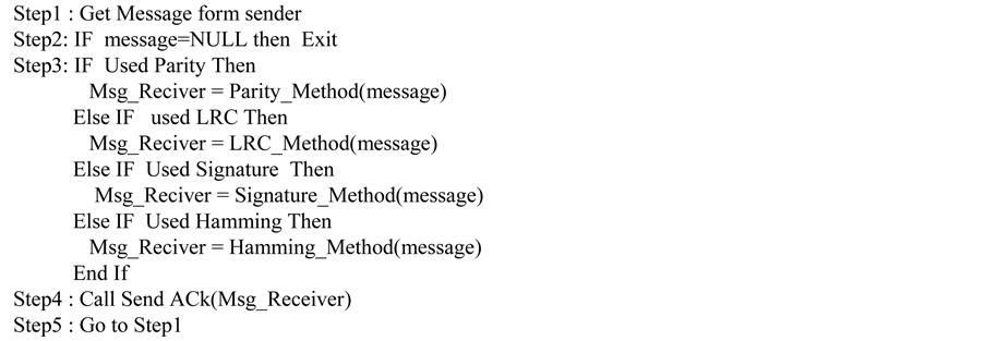
After receiving the non-empty message, the receiver will extract data and the used method in order to insert the data in the manipulation process for checking the correctness. According to the results the receiver sends an acknowledgement to sender for continuity or resending. The ulterior steps show how sender works and manipulates data.
Receiver Steps:
5. Experiments and Results
The proposed detection algorithm and the other existing ones were tested with a different data and different packet size. The evaluation measured parameters that were utilized in the testing are: execution time, number of sending, and correctness [11] . Table 2 shows the results of testing those method at packet size 10 and file size 359 KB.
The results for measurement at previous data are shown in Figure 6. As you see hamming code always has the maximum execution time due to its high ability to detect errors, which is required a higher computation time than other methods, while signature is the minimum execution time due to its weakness in detecting errors. Drop false is one of weakness of signature method in which it accept error as correct packet specially if the signature contains one’s in all locations. Every time there is a tradeoff between execution time and correctness, high execution time with high correctness as in hamming method. LRC and parity approximately have the same measurement.
Table 3 and Figure 7 are another case for detection algorithms that proves the same results as in the previous case.
Table 2. Results of detection methods at packet size = 10 and file size = 359 KB.
Table 3. Results of detection methods at packet size = 20 and file size = 730 KB.

Figure 6. Results of detection methods at packet size = 10 and file size = 359 KB.

Figure 7. Results of detection methods at packet size = 20 and file size = 730 KB.
6. Conclusions
Hamming code method is a powerful technique for detecting errors but as we mention previously a tradeoff between execution time and correctness which makes the usability is hard in wireless communication. LRC is an intermediate method between correctness and execution time so it is better to use it over the other methods.
Results of any simulator will base on the correctness of collected data. In generating noise if we know the approximate statistical distribution, the results become more accurate and more nearby to the reality.
Cite this paper
Mohammed J.Bawaneh,Mahmud S.Alkoffash,ShihadehAlqrainy,HasanMuaidi, (2016) A Practical Comparison between Signature Approach and Other Existing Approaches in Error Detection over TCP. Communications and Network,08,31-38. doi: 10.4236/cn.2016.81004
References
- 1. Tanenbaum, A.S. (2003) Computer Networks. 4th Edition, Prentice Hall, Upper Saddle River, Chapter 3, Section 3.2, Electronic Book.
- 2. Liu, H., Ma, H.R., El Zarki, M. and Gupta, S. (1997) Error Control Schemes for Networks: An Overview. Journal Mobile Networks and Applications, 2, 167-182.
http://dx.doi.org/10.1023/A:1013676531988 - 3. Forouzan, B.A. (2001) Data Communication and Networking. 2nd Edition, McGraw-Hill, Boston, Chapter 9, 273-292.
- 4. Chung, S.-J. (2001) Network Architecture: Hamming Codes and Cyclic Redundancy for Transmission Error Correction. ACM SIGCSE Bulletin, 33, 48-50.
http://dx.doi.org/10.1145/572139.572169 - 5. Aikawa, S., Motoyama, Y. and Umehira, M. (1997) Error Correction and Error Detection Techniques for Wireless ATM Systems. Wireless Networks, Kluwer Academic Publishers, Norwell.
http://dx.doi.org/10.1023/A:1019169620410 - 6. Alexiou, A., Bouras, C. and Papazois, A. (2011) A Study of Forward Error Correction for Mobile Multicast. International Journal of Communication Systems, 24, 607-627.
http://dx.doi.org/10.1002/dac.1178 - 7. Akyildiz, I.F., Joe, I., Driver, H. and Ho, Y.-L. (2001) An Adaptive FEC Scheme for Data Traffic in Wireless ATM Networks. IEEE/ACM Transactions on Networking, 9, 419-426.
http://dx.doi.org/10.1109/90.944340 - 8. Miller, J. and Cozzens, M. (2010) Crypto Book Working Notes, Princeton University Press Princeton and Oxford, Error Detect Correct Factorization, 26 August 2010, Chapter One, 1-22.
- 9. Wobbrock, J.O. and Myers, B.A. (2004) Analyzing the Input Stream for Character-Level Errors in Unconstrained Text Entry Evaluations. ACM Transactions on Computer-Human Interaction (TOCHI). Journal ACM Transactions on Computer-Human Interaction (TOCHI), 13, 458-489.
http://dx.doi.org/10.1145/1188816.1188819 - 10. Makris, Y. (2005) Concurrent Error Detection in Asynchronous Burst-Mode Controllers Sobeeh Almukhaizim. Proceedings of the Design, Automation and Test in Europe Conference and Exhibition (DATE’05), IEEE Computer Society, 1530-1591/05.
- 11. Krautz, U., Pflanz, M., Jacobi, C., Tast, H.W., Weber, K. and Vierhaus, H.T. (2006) Soft Error Analysis and Concurrent Testing: Evaluating Coverage of Error Detection Logic for Soft Errors Using Formal Methods. Proceedings of the conference on Design, Automation and Test in Europe: Proceedings DATE’06, 6 March 2006, 176-181.