World Journal of Mechanics
Vol.06 No.03(2016), Article ID:65113,14 pages
10.4236/wjm.2016.63008
Analysis and Design of Thermally Actuated Micro-Cantilevers for High Frequency Vibrations Using Finite Element Method
Mojtaba Komeili, Carlo Menon
Menrva Research Group, School of Engineering Science, Simon Fraser University, Burnaby, Canada

Copyright © 2016 by authors and Scientific Research Publishing Inc.
This work is licensed under the Creative Commons Attribution International License (CC BY).
http://creativecommons.org/licenses/by/4.0/


Received 7 February 2016; accepted 26 March 2016; published 29 March 2016
ABSTRACT
Vibrational behavior of thermally actuated cantilever micro-beams and their mechanical response at moderately high frequency under a non-harmonic periodic loading is studied in this paper. Two different configurations are considered: 1) a straight beam with two actuation layers on top and bottom which utilizes the bimorph effect to induce bending; 2) a uniform beam with base excitation, where the beam is mounted on an actuator which moves it periodically at its base perpendicular to its axis. Generally, vibrating micro-cantilevers are required to oscillate at a specified frequency. In order to increase the efficiency of the system, and achieve deflections with low power consumption, geometrical features of the beams can be quantified so that the required vibrating frequency matches the natural frequencies of the beam. A parametric modal analysis is conducted on two configurations of micro-cantilever and the first natural frequency of the cantilevers as a function of geometrical parameters is extracted. To evaluate vibrational behavior and thermo- mechanical efficiency of micro-cantilevers as a function of their geometrical parameters and input power, a case study with a specified vibrating frequency is considered. Due to significant complexities in the loading conditions and thermo-mechanical behavior, this task can only be tackled via numerical methods. Selecting the geometrical parameters in order to induce resonance at the nominal frequency, non-linear time-history (transient) thermo-mechanical finite element analysis (using ANSYS) is run on each configuration to study its response to the periodic heating input. Approaches to improve the effectiveness of actuators in each configuration based on their implementation are investigated.
Keywords:
Micro-Electro-Mechanical Systems, Finite Element, Thermal Actuations, Micro-Cantilever, Dynamic Thermo-Mechanical Analysis

1. Introduction
The demand for devices with smaller size, higher accuracy and lower energy consumption in different industries, along with advancements in micro-level manufacturing and micromachining, has led to innovative developments in the field of micro-electro-mechanical systems (MEMS) during the last decades. MEMS devices are primarily designed and implemented for two general purposes: sensing and actuation [1] . Both have various applications in advanced industries such as telecommunication [2] , atomic force microscopy [3] , high accuracy sensors [4] , medical devices [5] and a variety of other different applications and fields [1] .
The small size of the MEMS components results in characteristic behaviors of these devices. Thus, specific considerations must be kept in mind while analyzing the behavior of the micro-structures [6] and even the material properties of the components compared to the ones of their bulk material in larger scales [7] [8] . Among different structural configurations of the MEMS devices the cantilever micro-beam is of high interest in a variety of applications due to its simplicity in design and manufacturing, and well-established foundations to study its behavior and performance. Micro-level beams with cantilever boundary conditions (also known as micro-canti- lever) have been studied and implemented for different applications in MEMS. For instance, micro-cantilevers have been advantageously used for scanning probe in atomic force microscopy [9] [10] , particle mass sensing [11] , frequency doublers in electrical signal processing [12] and variety of other practical applications in automotive, aerospace and medical industries [1] .
The focus of this paper is on micro-cantilever actuators. Using conventional macro-level actuation (e.g., electrical motors, hydraulic jacks etc.) is not practically possible in micro-level; however, alternative methods such as piezoelectric [9] [13] [14] , electro-static [15] [16] and thermal/electro-thermal actuation [2] [11] [17] are widely in use for real-world applications. Amongst these methods, thermal actuation has some benefits over other methods. For example, integration of heating elements in the micro-system is easier than piezoelectric and electrostatic; there are more options for the heating materials to be used, and higher magnitude of forces can be delivered with lower power input [1] [18] [19] . Moreover, due to the small length and miniature volume of the components, the thermal time constant of the part (actuator) is very short which in turn allows the micro-beam to heat/cool in a very short time period. Thus, it has been reported that thermal actuators in MEMS can induce periodic thermal cycles with frequencies in range of MHz and even up to a few GHz [20] . In order to increase the efficiency of the system and have maximum displacement at the beam’s tip point with minimum energy/power input, it is preferable to excite the structure in its natural frequency and use the effect of the beam’s resonance.
This paper studies the mechanical vibration of a thermally actuated micro-cantilever. The ultimate goal of this research is formulating general guidelines for optimizing the design of a micro-cantilever that vibrates in a specified nominal frequency. Two different approaches for the architecture and actuation of the micro-beam are considered. The first one is based on inducing bending using thermal expansion and bimorph effect that occurs in a beam with multiple layers and different thermal expansion coefficient on those layers. The second design is based on inducing lateral motion in a beam through base excitation. In the latter, the actuator is acting as a moving base for the beam with distributed mass. Motion is applied in a direction perpendicular to the beam axis and induces vibration in the beam and eventually displacement of its tip. A case study is explored with a particular design frequency, i.e., 8 kHz which is a typical frequency for scanning fiber endoscopy application [21] . General recommendations to increase the efficiency of system by manipulating the actuators design are drawn from these simulations. Eventually, the performance of the two beam configurations is compared and conclusions are presented. Based on these results guide-lines for optimized design of thermally actuated micro-cantilevers are proposed.
2. Geometry and Analytical Model
Two suggested geometrical configurations mentioned above are shown in Figure 1. The first configuration, referred hereafter as “Configuration A” (Figure 1(a)), consists of a beam that is sandwiched between two layers of a different material at the clamped end. The top and bottom layers of the material act as antagonist actuators and expand when heated via an electric current. This expansion induces a shear on the interface layer between two beams that results in bending. Alternating heating between top and bottom layer makes the beam to vibrate. The second configuration (“Configuration B”) shown in Figure 1(b) is based on the lateral motion on the base of a suspended beam. In both configurations, if the frequency of the excitation is close enough to the first natural frequency of the beam, amplified displacements can be expected at the tip of the cantilever due to resonance.
 (a) (b)
Figure 1. The geometry of two suggested cantilevers and geometrical parameters. (a) Configura- tion A; (b) Configuration B.
2.1. Equation of Motion and Physical Assumptions
The general form of equation of motion for an Euler-Bernoulli beam is given to be [22] :
 (1)
(1)
where x is the axial coordinate of the beam, along its direction, y is the lateral displacement/deflection in beam at location x at time t; m is the mass per unit length of the beam, and E and I are the Young’s moduli and Second moment of area for beam cross section, respectively. Note that in general, m, E and I can be considered to be variable along the beam (a function of x) as they can change by change in the cross section.
Keeping in mind that for the modal analysis the harmonic response of the system is going to be considered,  can be replaced by its harmonic form,
 . In which
  is the amplitude of harmonic displacement at each location, and
 . Therefore, the above equation can be rewritten as:
 (2)
(2)
Solving Equation (2) requires knowing the boundary conditions on two sides of the beam. Figure 2 demonstrates the boundary conditions and assumptions used for each configuration in order to be able to find their first natural frequency using the above equation. As it can be seen, in Configuration A (Figure 2(a)) the beam is separated into two sections. The reason is the fact that Equation (2) can be readily solved if m, E and I are constants. Separating the beam into two sections and relating them through their boundary conditions at the interface can allow us to solve the problem easier. For Configuration B (Figure 2(b)), the flexural rigidity of the part with actuator is considerably higher than the floated section of the beam. Therefore, the connection of the beam to the actuator can be assumed to act as a clamped connection.
2.2. Mathematical Formulation for Modal Analysis
Figure 2 depicted the schematic of the beams and the fact that Configuration A is separated into two different segments. This allows to treat each segment as a uniform beam. Degrees of freedom that are used as boundary condition on each section are also depicted on the latter figure. Considering the fact that attention is only the first flexural mode of the beam, the discrete model of beam can have adequate accuracy for the purpose [23] . Thus, the following equation, which is driven from Equations (1) and (2) can be used:
 (3)
(3)
where  is the degrees of freedom vector for each beam section which contains displacement (
 ) and slope (
 ) at the first/beginning and second/end node (i subscript representing the node number) of the beam element, and dot operators on top of the variable represents its derivative with respect to time.
 ,
,  and
and  are the mass and stiffness matrices and external force vector, respectively. For the case of
 (a) (b)
Figure 2. (a) Boundary condition on the cantilever and beam segments for Configuration A; (b) Boundary conditions on Configuration B.
free vibration analysis  and
and  [22] . Therefore Equation (3) will be simplified to:
 (4)
(4)
Knowing the mass and stiffness matrix, Equation (4) can be solved as an eigenvalue problem to find the natural frequencies. The mass and stiffness matrices can be driven from elasticity and dynamic equations as following [23] - [25] :
 (5a)
(5a)
 (5b)
(5b)
in which L is the length of the beam section under consideration ( , where
  is the location of node j).
Matrices in Equation (5) contain the equations for one beam section with homogenous properties. To increase the accuracy of obtained results it is customary to break down (discretize) length of each beam segment into multiple sections which are described by these equations and then establish proper boundary conditions between them in the connection nodes. It can be done by filling the overall stiffness matrix according to the degrees of freedom or using the gatherer matrix to assemble the overall stiffness matrix [26] . As a result of dividing the beam segment into multiple sections, more degrees of freedom along beam are taken into account and the overall behavior of discrete system gets closer to the exact solution from Equation (1).
3. Modal Analysis
To find the first natural frequency of the system, two different approaches are implemented here. First one is based on the analytical model presented above and the second is running a Finite Element modal analysis on the 2D model of each configuration. For the latter, the commercial package of ANSYS® is selected. Details and outcome of each method is described in the following. The material used for the core of this micro-cantilever is Silica (optical fibers) and actuators are selected to be Aluminum.
3.1. Analytical Discrete Beam Model
The natural frequencies of a system can be extracted by applying its boundary conditions and solving for the eigenvalues. For the current micro-cantilever and system of equations in Equation (4) using a single element for the entire beam is not usually recommended in the dynamic/modal analysis even for a beam with uniform features along its length (e.g., Configuration B). So, each beam segment is discretized into multiple sections for more accuracy and resemblance to the original continuous system. A MATLAB® code, written by the authors, breaks down beam into smaller beams/sections, generates stiffness and mass matrices for each element based on Equation (5), and then assembles the overall stiffness and mass matrix using the gatherer matrix approach [26] . The minimum number of elements along beam section that assures satisfactory convergence for different length and thickness values is found by trial and error and checking the results over a nominal length. It was concluded that for a uniform beam, using a total number of 10 sections/elements along the length of the beam results in an answer which is close to the answer obtained by solving Equation (1) analytically (~1.0% error). As a result, each beam configuration is discretized into 10 smaller elements for finding the eigenvalues of the whole system. Due to 2-dimensional nature of the system the out of plane thickness does not play an important role in the final outcome (plane-stress conditions apply).
Figure 3 shows the natural frequency of the Configuration A cantilever as a function of beam length and thickness, for four different combinations of actuator length and thickness. Similarly, Figure 4(a) illustrates the natural frequencies of the second configuration (B) as a function of the beam length and thickness. Because of the uniform cross section of this configuration, Equation (1) can readily be solved using the analytical method, where the natural frequency of the cantilever for the first mode is given to be [27] :
 (6)
(6)
Figure 4(b) shows the natural frequencies of Configuration B as found through Equations (6). As it can be seen, practically identical results are obtained using either formulation.

Figure 3. First natural frequency for Configuration A using the discrete beams method.
 (a) (b)
Figure 4. First natural frequency for Configuration B. (a) Using the discrete beams method; (b) Using the formulation of a homogenous continuous beam.
3.2. 2D Finite Element Model
The 2D model was made in ANSYS using the plane stress assumption for the formulation of elements (Plane13 elements [28] ). A MATLAB® script was used as an interface along with an ANSYS APDL file to run different combinations of the geometrical parameters in order to extract the response surfaces similar to the procedure done for the analytical discrete beam model in previous section. Figure 5 and Figure 6 represent the natural frequencies of cantilever for configurations A and B, respectively. Capabilities of finite element method in simulating systems with more complexity in their geometrical and mechanical features allows for taking the geometry of the actuators into account in Configuration B.
As it can be noted from Figures 3-6, the general trend shows that the natural frequency is directly related to thickness and inversely related to length, as was expected. Color maps also show the regions with combinations of length and thickness that can result in a target frequency (e.g., 8 kHz which is considered in the next case study) for each configuration. Any selected value in these regions can be used for design of the cantilever beam in that particular frequency. Selecting the suitable values for the final dimensions of each micro-cantilever configuration is more dependent on other design requirements of the system. In this research, goal is reaching the maximum magnitude of deflection at the tip point using the minimum energy as input. Therefore, the combination of minimum thickness (lower flexural rigidity) and higher length (higher deflection with similar radius of curvature) will be a more preferable combination for this purpose.
4. Transient Analysis
The dynamic response of each cantilever configuration to the periodic heat input is studied at excitation frequency of ~8 kHz. Exciting cantilever in its first natural/resonance frequency maximizes deflection at its tip point that may result in large deformations. Indeed, inducing this high magnitude of deflection is the main goal of this design/research. Taking into account the effect of heat convection on the free surfaces, thermo-mechani- cal coupling, non-harmonic nature of heating, and large deformations, it can be noticed that this system has high level of non-linearity and therefore cannot be tackled using a simple harmonic analysis. Thus, simulation of dynamic response using transient finite element simulation is investigated as only practical approach.
This case study considers four different combinations of actuator length and thickness for each configuration. The geometrical details are summarized in Table 1. Keeping the beam thickness constant (t = 6 µm), the beam length has been optimized to make the natural frequency as close as possible to 8 kHz. Natural frequencies can be estimated using either of methods described above without noticeable discrepancies. Considering that actuator in Configuration A is part of the beam while in Configuration B works as an attachment to the base, the overall length of the beam is changing noticeably for Configuration A to achieve the required frequency while it is quite constant for B. In addition, as it can be seen in Table 1, the natural frequencies are not exactly on 8 kHz, nonetheless they are practically close enough to the target. Manipulating the geometrical dimensions to achieve

Figure 5. First natural frequency for Configuration A using 2D FEA.
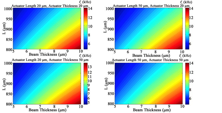
Figure 6. First natural frequency for Configuration B using 2D FEA.

Table 1. Selected geometrical parameters for cantilever configurations.
a closer value of the natural frequency does not necessarily improve the results in the final manufactured cantilever due to all other tolerances and uncertainties which are impossible to control.
Excitation is done via electro-thermal heating of the actuator material (Aluminum layer in this case). Thus, in the ANSYS model a periodic body heat generation is applied on the actuator medium. The amount of heat generation can be calculated by the energy consumption in the actuator (or vice versa). Due to the fact that the heat generation happens in the actuator regardless of electric current direction, using sinusoidal electric currents for the heating results in two half heating cycles. This leads to periodic heating with a frequency twice as the electrical current frequency. On the other hand, utilizing design specific circuitry, one half-cycle can be removed in order to allow the cooling part of the heating/cooling sequence happen during that interval. In other words,
in-stead the periodic function  (which directly comes from the sinusoidal current),
 is used as the periodic term in the body heat generation function. For Configuration
A this function has been applied to the actuators on both sides, however, a half cycle ( ) shift is included between the actuators. As a result an effect similar to a full periodic actuation can be emulated on the beam for its bending. Because of low damping in the Aluminum and Silica the natural frequency calculated in previous section will not be affected considerably by effect of material damping, however, it is proven that for structures excited at their resonance frequency material damping is a crucial factor in their steady state response and quality factor [22] . Considering the options available for this particular analysis (time-history) in ANSYS [28] , the damping of the beam and actuator material are incorporated into simulation using the Rayleigh damping and the average loss modulus reported for Aluminum and Silica [29] . The mass proportional damping is ignored and only the stiffness proportional damping is taken into account regarding the fact that for most of solids with low damping this results in higher accuracy [28] .
4.1. Effect of Air Damping
For the vibration of micro-cantilever inside a fluid (air in this case), there are studies that show the most important effect from surrounding fluid is from squeeze film damping [30] . This type of damping is effective when the thickness of fluid trapped between beam and the adjacent wall/obstacles is smaller than one third of beam thickness [31] . On the other hand, the effect of drag on the quality factor of vibration in beams with small width, vibrating on frequency ranges below 1 MHz can be neglected without losing significant accuracy [32] . Considering the fact that this beam has no adjacent structure (no squeeze film damping), assuming a thin out-of-plane thickness that reduces its drag significantly [32] , the effect of air damping is ignored in the time-history analysis. It should be mentioned that similar studies show that the frequency shift from resonance frequency is considerably low under the effect of air drag damping for the current length scale of beam and the vibration frequency [32] .
4.2. Thermal Boundary Conditions
The mechanical boundary conditions applied on the model are as described on the previous section on modal analysis. However, due to thermo-mechanical coupling and the fact that the main loading mechanism in this analysis is the thermal heating and dissipation, proper thermal boundary conditions are of utmost importance. For this simulation the clamped side of the beam is treated as a heat sink with constant temperature (constraint on temperature degree-of-freedom) equal to the reference temperature and due to exposure of the other edges to air, heat convection boundary condition is required along the other edges.
The convective heat transfer coefficient ( ) for solids exposed to air is a variable depending on parameters such as pressure of ambient air and fluid velocity. The fact that the relative velocity of air has different values on different locations along the beam makes dealing with this parameter extraordinarily hard to tackle. To study the importance of
  on general behavior of this simulation a sensitivity analysis was conducted on the effect in the thermal response of the system. Because thermal effects are the main focus in this sensitivity analysis, only temperature degree of freedom is taken into account. Experiments show that for air under free or forced
convection , in practice [33] . Thermal simulation on this model was done with an 8 kHz
frequency over a time-span of 40 cycles (5 ms) to assure the thermal steady state. Figure 7 shows the general trend of temperature distribution in each beam. Although, the distribution of temperature is periodic with time,
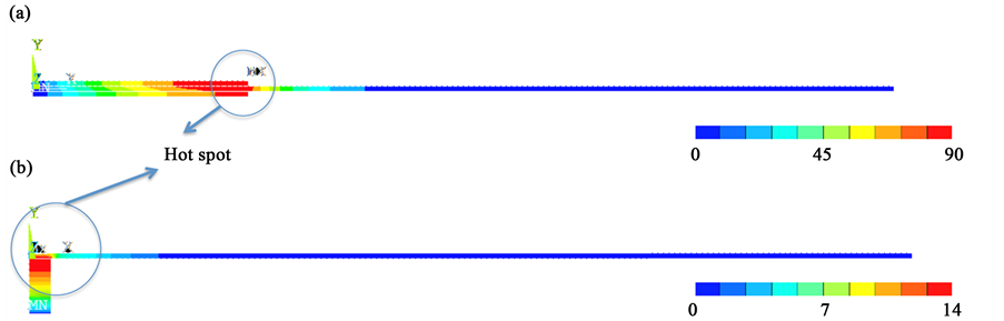
Figure 7. Temperature distribution and location of hot spot in time-history (transient) analysis. (a) Configuration A; (b) Configuration B.
its general distribution in terms of maximum and minimum temperature is similar to the depicted contours. Constant values of  selected from the abovementioned range were inserted into the simulation as the heat convection coefficient on all the exposed surfaces and the end result with these values were compared. Eventually, it was noticed that the convective heat transfer coefficient (
 ) has negligible effect in the temperature distribution on each beam and can be ignored. To demonstrate this, areas with the maximum temperature are denoted as “hot spots” (Figure 7) and their temperature with three different values of
  is plotted in Figure 8 as a function of time. These three values include: minimum (0), maximum (110) and a fictitious value ten times higher than the maximum value to demonstrate the extreme case (1100). The body heat generation function:
 (7)
(7)
where q is the constant amplitude of heat generation per unit volume is used as thermal loading function. A magnitude of  is selected for this sensitivity study.
As it can be noted in Figure 8, the effect of  on the temperature in the hottest point on the cantilever (which is the point affected by it the most) is hardly noticeable. This can be related to the very small area of the free surfaces of beam. On the other hand, the short distance between each point on the beam to the heat sink and high temperature difference, which results in large temperature gradient, makes heat conduction the dominant cooling mechanism in the system. As a result, the effect of heat convection on the free surface of beam is neglected later on for dynamic thermo-mechanical analysis.
4.3. Results of Time-History Analysis
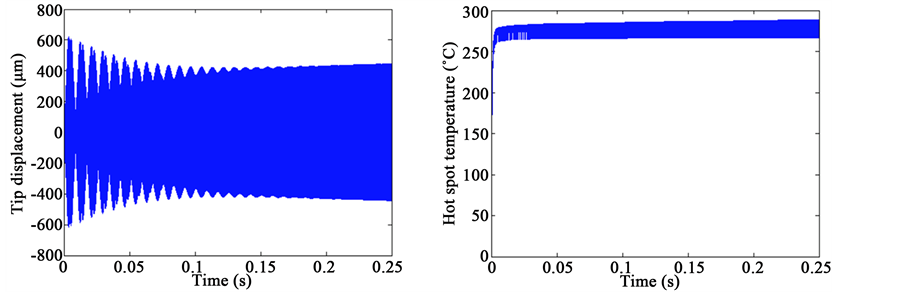
After establishing the FE model with the details mentioned above and including the effect of thermo-mechanical coupling, different magnitudes of input power are implemented in the dynamic time-history model and the displacement at the tip of beam as well as the hot spot temperature are recorded. The transient finite element runs are computationally expensive and for current simulation each run takes tens of hours on a workstation computer. The periodic body heat generation is applied with a frequency equal to the frequencies mentioned in Table 1 for each case. FE simulation was continued for long enough elapsed time to assure steady state. The mesh and time-step sizes were refined up to the point to assure convergence to less than ~5% error. Then, the amplitude of displacements after achieving steady state was estimated via averaging the peak values (both maximum and minimum). Figure 9 and Figure 10 show the tip displacement and hot spot temperatures for two samples excited with 20 mW input power for configuration A and B, respectively. The input power for each actuator can be calculated from:
 (8)
(8)
where  is the period of vibration, and V is the volume of actuator. The out-of-plane thickness of the
 (a) (b)
Figure 8. Temperature at a selected node at hot spot for different magnitudes of convective heat transfer coefficient. (a) Configuration A; (b) Configuration B.
 (a) (b)
Figure 9. Dynamic response of Configuration A (L200 T2) under 20 mW input power.
 (a) (b)
Figure 10. Dynamic response of Configuration B (L50 T50) under 20 mW input power.
system can be important in this parameter and it is assumed to be the same as the beam thickness hereafter, without losing generality. Note that for Configuration A,  must be multiplied by 2 because there are two actuators that receive energy on each period and although they are out of phase by π, they are using same amount of energy every cycle. Inverse of Equation (8) can be used to find the amount of body heat generation as a function of input power.
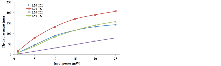
Figure 11 and Figure 12 depict the tip displacement amplitude and hot spot temperature change after
 (a)
(a)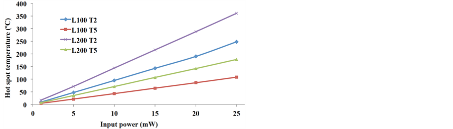 (b)
(b)
Figure 11. Dynamic response of Configuration A as a function of input power. (a) Tip displacement; (b) Hot spot temperature.
 (a)
(a) (b)
(b)
Figure 12. Dynamic response of Configuration B as a function of input power. (a) Tip displacement; (b) Hot spot temperature.
reaching the steady state as a function of input power for configuration A and B, respectively. Comparing different values of actuator thickness and length, following conclusions can be drawn for each configuration.
The general trend shows increase in the tip displacement and hot spot temperature by raising the amount of input power (as was expected intuitively). However, while the temperature increases in a close to linear pattern, the tip displacement has a sharper growth initially and the slope tends to diminish at higher input powers. This can be related to the fact that temperature is directly related to the input thermal energy [33] , whereas, in an analogy with a one-degree-of-freedom system the mechanical energy is related to the squared value of vibration
amplitude [22] . Thus, a trend of  can be noticed in Figure 11(a) and Figure 12(a).
Supplying same amount of input energy, the tip-displacement in Configuration A is generally higher than Configuration B, and the same applies to the hot spot temperature. The thin and long shape of the actuators in Configuration A allows them to exert their excitation on a larger area along the beam and directly bend a larger portion of beam, but it makes the hot spot too far from the heat sink and the conduction passage narrow. On the contrary, Configuration B utilizes a local excitation at the base, but much smaller aspect ratio facilitates the cooling through conduction. This points out that each configuration can have its advantages and disadvantages that can be studied more elaborately in an optimization process with constraints.
Focusing on Configuration A, it might have been expected that the longer actuator length and thickness would increase the tip displacement due to higher extension and stiffness of actuator (case that happens in static conditions and uniform temperature change). But, note that the distribution of temperature in the actuator and local elongation plays an important role in bending during vibration. Figure 11(a) shows that actuator with shortest length and smallest thickness (L100 T2) has a generally superior performance in terms of tip displacement. However, this does not mean lower length and thickness results in higher tip displacement (as it can be seen the longest and thickest actuator [L200 T5] comes next in ranking). Keeping in mind that the total beam length had to be changed in this configuration. It can be concluded that there is a significant correlation to the combined effect of actuator length and thickness, and beam length. The time-dependent local temperature along the actuator has an effect on the radius of curvature on that location which influences the overall deflection. On the other hand, the deflection of beam changes the geometry of actuator and affects the heat distribution in return. The complex situation makes the effect of actuator dimensions and beam length on the beam dynamics not readily predictable. Case dependent optimizations are required to find the optimums as a function of beam length, actuator length and thickness. However, Figure 11(a) also shows that at lower input powers effect of actuator length is subtle compared to the actuator thickness and thinner actuator leads to higher displacements as a results of higher temperature increase.
The hot spot temperature shows a more predictable and straightforward phenomenon (Figure 11(b)). It confirms that increasing actuator length and decreasing its thickness will increase the overall hotspot temperature (as expected from the heat conduction physics discussed before).
The behavior of Configuration B as seen in Figure 12 clearly shows that increasing thickness and decreasing length in general results in higher tip deflection as well as higher hot spot temperature. The higher thickness in the actuator means the temperature in the hot spot is higher because of more distance to the sink. On top of that, the elongation of actuator is higher under an equal temperature change. Thus, overall higher base excitation is applied on the beam and magnified at the tip due to resonance effects. On the other hand, longer actuator means the heat generation is spread over a larger area and thermal energy can be transferred to the sink easier, therefore effective temperature change is lower. As a result, the hot spot temperature is reduced and subsequently, less tip displacement is achieved.
5. Conclusions
In order to increase the efficiency of vibrating micro-cantilevers they are usually excited in their natural frequencies. This helps to induce resonance and achieve a large magnitude of vibration with small actuation. A case study with four combinations of actuator length and thickness for two different configurations is considered here. It shows a sensitivity analysis for designing a vibrating micro-cantilever in a specific frequency (8 kHz).
Modal and time-history (transient) coupled thermo-mechanical analysis is conducted on 2D model of the selected designs. A preliminary thermal analysis on the systems shows that in both configurations effect of thermal convection from ambient air can be ignored because of small area of the surfaces and dominant effects of thermal conduction. Thus, mechanical and thermal boundary conditions (except thermal convection) are applied on the system and the dynamic response is recorded over long enough time to assure steady state.
General comparison between all designs generally shows similarities in the displacement and hot spot temperature trends as a function of input power, although magnitudes are notably different. Basically, Configuration A provides more tip displacement in the cost of higher temperature at the hot spot compared to the Configuration B. The displacement magnitude for Configuration A does not show a direct correlation with actuator thickness and length. A high-level of correlation between these two variables and beam length exists and practical implementations must explore this correlation in more details for specific designs in order to achieve optimal performance. On the other hand, a direct correlation between actuator length and thickness in Configuration B can be observed through the graphs. Increasing actuator thickness and/or decreasing actuator length increase tip displacement, as well as hot spot temperature.
In conclusion, this study shows the plausibility of the thermal actuation for achieving high displacement level in micro-cantilevers. In addition, general recommendation on the optimization of their dynamic performance is discussed. For future work, scientific research on phenomenon such as response on other frequencies and potential effect of ambient air through fluid solid interaction, as well as thermal resonance [34] can be studied in future to acquire a better understanding of the underlying phenomenon in this system and subsequently its further optimization.
Acknowledgements
This study was supported by the Natural Sciences and Engineering Research Council of Canada (NSERC), the Canadian Institutes of Health Research (CHIR) and the Michael Smith Foundation for Health Research (MSFHR). The authors thank Drs. Pierre Lane and Marinko Sarunic, and Mr. Jamal Bahari for their comments provided during the course of this research.
Cite this paper
Mojtaba Komeili,Carlo Menon, (2016) Analysis and Design of Thermally Actuated Micro-Cantilevers for High Frequency Vibrations Using Finite Element Method. World Journal of Mechanics,06,94-107. doi: 10.4236/wjm.2016.63008
References
- 1. Maluf, N. and Williams, K. (2004) Introduction to Microelectromechanical Systems Engineering. Artech House Inc., Boston.
- 2. Feng, Z., Zhang, W., Su, B., Harsh, K.F., Gupta, K.C., Bright, V. and Lee, Y.C. (1999) Design and Modeling of RF MEMS Tunable Capacitors Using Electro-Thermal Actuators. IEEE MTT-S International Microwave Symposium Digest, Vol. 4, Anaheim, 13-19 June 1999, 1507-1510.
- 3. Kolluru, S.K.K. (2010) Mems Atomic Force Microscope. Texas Tech University.
- 4. Bogue, R. (2007) MEMS Sensors: Past, Present and Future. Sensor Review, 27, 7-13.
http://dx.doi.org/10.1108/02602280710729068 - 5. Kotzar, G., Freas, M., Abel, P., Fleischman, A., Roy, S., Zorman, C., Moran, M.J. and Melzak, J. (2002) Evaluation of MEMS Materials of Construction for Implantable Medical Devices. Biomaterials, 23, 2737-2750.
http://dx.doi.org/10.1016/S0142-9612(02)00007-8 - 6. Lobontiu, N. and Garcia, E. (2005) Mechanics of Microelectromechanical Systems. Kluwer Academic Publishers, Dordrecht.
- 7. (2001) The MEMS Handbook. CRC Press, Boca Raton.
- 8. Allameh, S.M. (2003) An Introduction to Mechanical-Properties-Related Issues in MEMS Structures. Journal of Materials Science, 38, 4115-4123.
http://dx.doi.org/10.1023/A:1026369320215 - 9. Iloh, T., Ohashi, T. and Siiga, T. (1996) Piezoelectric Cantilever Array for Multi-Probe Scanning Force Microscopy. Ninth Annual International Workshop on Micro Electro Mechanical Systems, 451-455.
- 10. Volden, T., Zimmermann, M., Lange, D., Brand, O. and Baltes, H. (2004) Dynamics of CMOS-Based Thermally Actuated Cantilever Arrays for Force Microscopy. Sensors and Actuators A: Physical, 115, 516-522.
http://dx.doi.org/10.1016/j.sna.2004.03.058 - 11. Hajjam, A., Wilson, J.C., Rahafrooz, A. and Pourkamali, S. (2010) Fabrication and Characterization of Thermally Actuated Micromechanical Resonators for Airborne Particle Mass Sensing: II. Device Fabrication and Characterization. Journal of Micromechanics and Microengineering, 20, 125019.
http://dx.doi.org/10.1088/0960-1317/20/12/125019 - 12. Basu, J. and Bhattacharyya, T.K. (2012) Microelectromechanical System Cantilever-Based Frequency Doublers. Journal of Intelligent Material Systems and Structures, 24, 240-246.
http://dx.doi.org/10.1177/1045389X12461695 - 13. Mahmoodi, S.N. and Jalili, N. (2007) Non-Linear Vibrations and Frequency Response Analysis of Piezoelectrically Driven Microcantilevers. International Journal of Non-Linear Mechanics, 42, 577-587.
http://dx.doi.org/10.1016/j.ijnonlinmec.2007.01.019 - 14. Mahmoodi, S.N. and Jalili, N. (2009) Piezoelectrically Actuated Microcantilevers: An Experimental Nonlinear Vibration Analysis. Sensors and Actuators A: Physical, 150, 131-136.
http://dx.doi.org/10.1016/j.sna.2008.12.013 - 15. Rezazadeh, G., Fathalilou, M., Shabani, R., Tarverdilou, S. and Talebian, S. (2009) Dynamic Characteristics and Forced Response of an Electrostatically-Actuated Microbeam Subjected to Fluid Loading. Microsystem Technologies, 15, 1355-1363.
http://dx.doi.org/10.1007/s00542-009-0906-2 - 16. Dong, J. and Ferreira, P.M. (2009) Electrostatically Actuated Cantilever with SOI-MEMS Parallel Kinematic XY Stage. Journal of Microelectromechanical Systems, 18, 641-651.
http://dx.doi.org/10.1109/JMEMS.2009.2020371 - 17. Hajjam, A., Rahafrooz, A., Wilson, J.C. and Pourkamali, S. (2009) Thermally Actuated MEMS Resonant Sensors for Mass Measurement of Micro/Nanoscale Aerosol Particles. IEEE Sensors, Christchurch, 25-28 October 2009, 707-710.
http://dx.doi.org/10.1109/icsens.2009.5398557 - 18. Comtois, J.H., Michalicek, M.A. and Barron, C.C. (1998) Electrothermal Actuators Fabricated in Four-Level Planarized Surface Micromachined Polycrystalline Silicon. Sensors and Actuators A: Physical, 70, 23-31.
http://dx.doi.org/10.1016/S0924-4247(98)00108-3 - 19. Riethmuller, W. and Benecke, W. (1988) Thermally Excited Silicon Microactuators. IEEE Transactions on Electron Devices, 35, 758-763.
http://dx.doi.org/10.1109/16.2528 - 20. Rahafrooz, A., Member, S. and Pourkamali, S. (2011) High-Frequency Thermally Actuated Electromechanical Resonators with Piezoresistive Readout. IEEE Transactions on Electron Devices, 58, 1205-1214.
http://dx.doi.org/10.1109/TED.2011.2105491 - 21. Lee, C.M., Engelbrecht, C.J., Soper, T.D., Helmchen, F. and Seibel, E.J. (2010) Scanning Fiber Endoscopy with Highly Flexible, 1 mm Catheterscopes for Wide-Field, Full-Color Imaging. Journal of Biophotonics, 3, 385-407.
http://dx.doi.org/10.1002/jbio.200900087 - 22. Thomson, W. (1996) Theory of Vibration with Applications. CRC Press, Boca Raton.
- 23. Kaveh, A. (2014) Computational Structural Analysis and Finite Element Methods. Springer International Publishing, Gewerbestrasse.
http://dx.doi.org/10.1007/978-3-319-02964-1 - 24. Felippa, C.A. (2013) Matrix Finite Element Methods in Dynamics. Department of Aerospace Engineering Science, University of Colorado, Denver.
- 25. Ferreira, A.J.M. (2009) MATLAB Codes for Finite Element Analysis. Springer, Berlin.
- 26. Fish, J. and Belytschko, T. (2007) A First Course in Finite Elements. John Wiley & Sons, Ltd, Chichester.
http://dx.doi.org/10.1002/9780470510858 - 27. Meirovitch, L. (1967) Analytical Methods in Vibrations. Prentice Hall, Upper Saddle River.
- 28. ANSYS Inc. (2014) ANSYS 15 Documentation. ANSYS Inc., Cecil Township.
- 29. De Silva, C. (2007) Vibration Damping, Control, and Design. CRC Press, Boca Raton.
http://dx.doi.org/10.1201/9781420053227 - 30. Hosaka, H., Itao, K. and Kuroda, S. (1995) Damping Characteristics of Beam-Shaped Micro-Oscillators. Sensors and Actuators A: Physical, 49, 87-95.
http://dx.doi.org/10.1016/0924-4247(95)01003-J - 31. Bao, M. and Yang, H. (2007) Squeeze Film Air Damping in MEMS. Sensors and Actuators A: Physical, 136, 3-27.
http://dx.doi.org/10.1016/j.sna.2007.01.008 - 32. Zhang, C., Xu, G. and Jiang, Q. (2003) Analysis of the Air-Damping Effect on a Micromachined Beam Resonator. Mathematics and Mechanics of Solids, 8, 315-325.
http://dx.doi.org/10.1177/1081286503008003006 - 33. Nowinski, J. (1978) Theory of Thermoelasticity with Applications. Sijthoff & Noordhoff, Alphen aan den Rijn.
http://dx.doi.org/10.1007/978-94-009-9929-9 - 34. Repin, A. (1993) Thermal Resonance in the Heat Conduction Problem with a Heat Source Moving along a Closed Circuit. Journal of Engineering Physics and Thermophysics, 65, 1097-1101.
http://dx.doi.org/10.1007/BF00862039