World Journal of Mechanics
Vol.3 No.1(2013), Article ID:27852,4 pages DOI:10.4236/wjm.2013.31004
The Mathematical Simulation of Brush Drums in a Dual Saw Cylinder Chamber Gin for the Purpose of Increasing the Quantity of Captured Cotton Fiber from Saw
Department of Mechanical Engineering, Lessius University College, Namangan Institute of Engineering and Technology, Namangan, Uzbekistan
Email: azizovshuhrat@gmail.com
Received November 11, 2012; revised December 14, 2012; accepted December 18, 2012
Keywords: Gin; Saw; Cotton; Brush Drum; Fiber; Saw Cylinder
ABSTRACT
An analysis of the efficiency of the ginning of cotton fibers with two saw cylinders has been carried out. In comparison to a one-cylinder machine, the 2 cylinder approach can help to preserve the natural characteristics of cotton fiber and seeds. This technology allows economizing electricity and decreasing damage to fiber and also increases the productivity of the machine.
1. Introduction
The effective analysis has been held on efficiency of removing the fibers from the teeth of two cylindrical saw through a brush drum. By doing this, the natural properties of cotton fibers are preserved.
Brush drums are installed for removing fibers stuck on the saw surface while coming out of the grid bar net. The drum should provide complete collection of fibers from the saw teeth without damaging seeds or saw teeth in case hard subjects appear in the zone [1].
The efficiency of a brush drum is characterized by the quantity of raw cotton which is collected from the surface of the saw cylinder and is estimated with a collection coefficient.
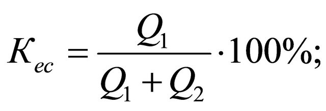 (1)
(1)
where  is the quantity of raw cotton collected from the brush drum and
  the quantity of raw cotton remaining on the surface of the saw. Intensity of processing the surface of saw cylinder by the brush drum is characterized the coefficient of influence [2].
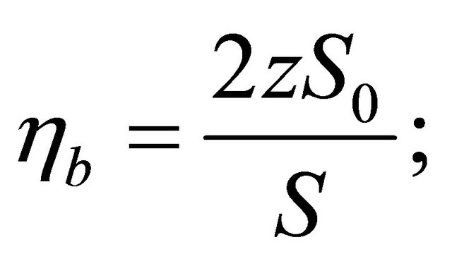 (2)
(2)
where: z—quantity of collecting sections on the brush drum; —area of the work surface of saw cylinder with a section of brush drum;
![]() —length of the circle of saw cylinder, when the brush drum rotate once.
—length of the circle of saw cylinder, when the brush drum rotate once.
 (3)
(3)
 (4)
(4)
The greater the indicator , the higher the efficiency of the brush drum.
2. Materials and Methods
According to Figures 1 and 2, the length of bow of the first saw drum equals
 (5)
(5)
the length of bow of the second saw drum equals where: —radius of the saw cylinder;
 —angle speed of saw cylinder 1;
 —type of time quantity of saw cylinder when turned to the angle
 ;
;
 (6)
(6)
where![]() —radius of the saw cylinder;
—radius of the saw cylinder; —ngle speed of saw cylinder 2;
 —type of time quantity of saw cylinder when turned to the angle
 ;
;
 (7)
(7)
 (8)
(8)
where: —angle speed of brush drum;
 —angle speed of saw cylinder 2.
Then,
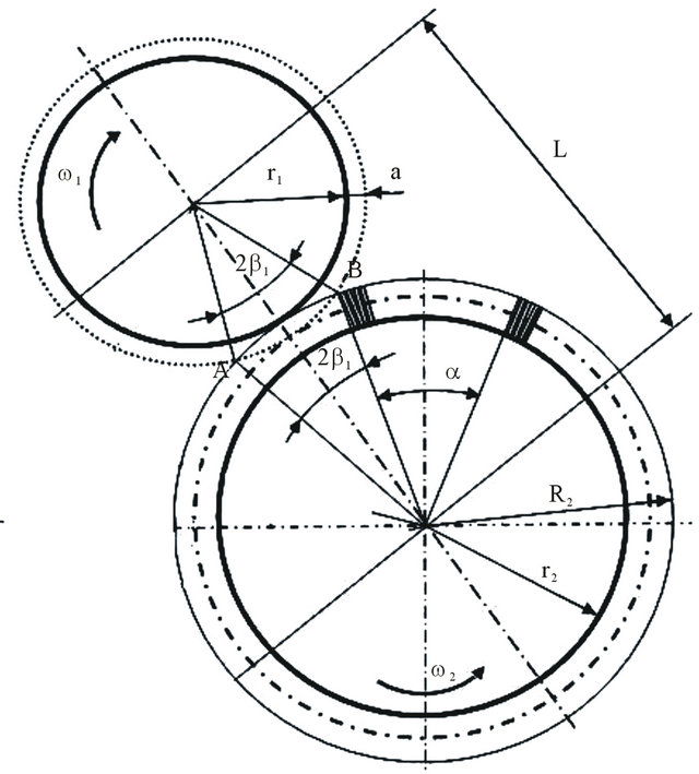
Figure 1. Schematic diagram and parameters of one saw cylinder.
Figure 2. Schematic diagram and parameters of two saw cylinder.
 (9)
(9)
а = 4 - 5 mm—thickness of the layer of raw cotton;
L = r1 + R2—distance between the centers of saw and brush drums;
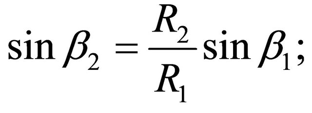
The size of the angles  &
&  determined in Figure 2:
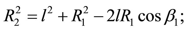 (10)
(10)
From which
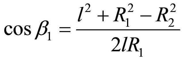 (11)
(11)
where: R1—radius of saw drum taking into account the thickness of the layer of coming out raw cotton.
 (12)
(12)
 (13)
(13)
The length of the bow of the saw cylinder circle, made per rotation of brush drum.
 (14)
(14)
where,
 (15)
(15)
![]() —time of one rotation of the brush drum.
—time of one rotation of the brush drum.
So as  Then
Then
 (16)
(16)
Putting the value of S0 and in formula (2) we get,
 (17)
(17)
For non-stop removal of fibers of raw cotton from the saw surface it is necessary that 
3. Numerical Results and Discussion
Changing the angle speeds in the formula corresponding to circumferential speeds and transforming them, we get the formulas of the relation of the speeds of the brush and the saw drum, which correlates all kinetic elements of the working unit of the drum brush [3]:
 (18)
(18)
In known values of the size it is possible to define the required quantity of the planks of brush drum stemming from the condition that in rotating the saw drum to the angle of  brush drum for collecting fibers, located in point A, should rotate to the angle of
 . So as the rotation time of saw drum to the angle of
  and the rotation time of brush drum
  are equal, it can be written
 (19)
(19)
Or
 (20)
(20)
In Figure 3 according to the coefficient K, change of α—angle between the sections two brushes is outlined
 (21)
(21)
α is an indication of angle of section between two brush.
Required quantity of planks on brush drum
 (22)
(22)
In Figure 4 according to the quantity of coefficient K, the change of numbers of brush section is outlined [3].
Efficiency of brush drum increases with the increase in
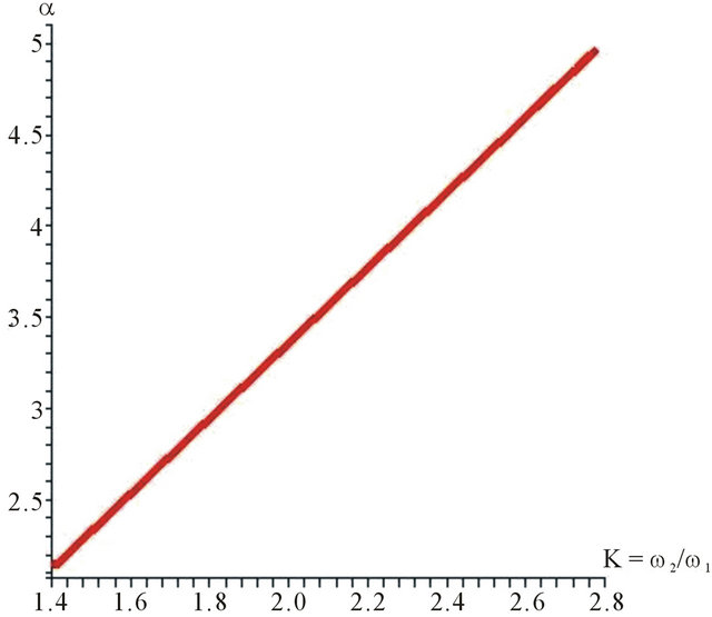
Figure 3. Schematic diagram α—angle between the sections two brushes is outlined.
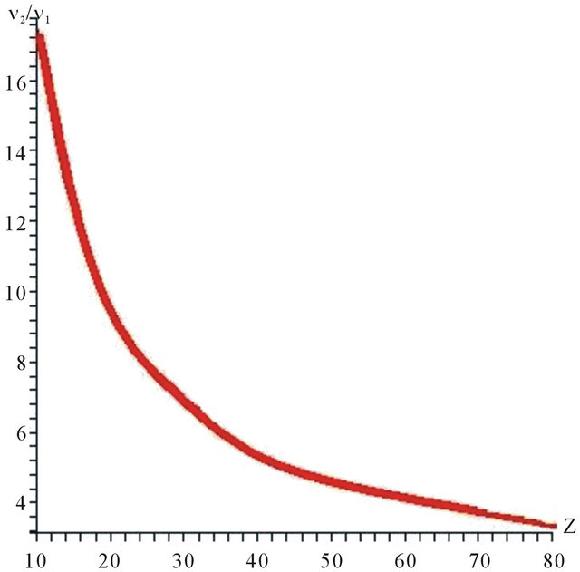
Figure 4. Schematic diagram change of numbers of brush section is outlined.
the coefficient of influence , which depends on the diameter and surrounding speeds of brush and saw drums. By the increase of the speed of brush drum or increase in its diameter the coefficient of influence increases, and with the decrease of the speed of saw drum fiber collecting surface increases. In Figure 5 according to the coefficient K, the change of quantity of
  coefficient is shown.
In Figure 6, according to the change of quantity of coefficient K, the length of arc of fiber quantity taken for a saw cylinder is shown. In graph, the length of arc in taking a fiber quantity in maximum degree equals to 700 мм. K1 = 2.8. In Figure 6 changes in the length of pickup S depending on the parameter of K. for one saw cylinder.
In Figure 7, according to the change of quantity of coefficient K, the length of arc of fiber quantity taken for two saw cylinder is shown. In graph, the length of arc in taking a fiber quantity in maximum degree equals to 1400 мм. In Figure 7, the change of length of arc in taking a fiber from two-saw cylinder is shown according to the . In graph, the length of way in taking a fiber in maximum degree consist of 1400 мм when it meets K2 = 2.8. In Figure 7 Changing the length of removal S in dependence of parameter K, for two saw cylinders.
Based on two-saw cylinder the quantity of taking a fiber increases and this leads to the improvement of productivity. The fiber taken from a first—saw cylinder through brush drum touches the next fiber in the teeth of second—saw cylinder and in this case, the fiber is taken carefully through brush drum preserving its natural features with no damage to it. This creates the opportunity of getting a fiber in good quality.
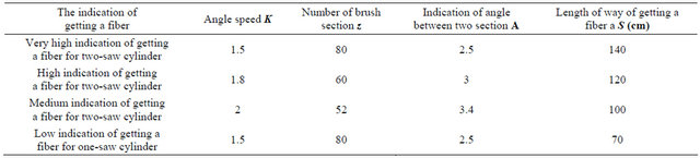
In Table 1, the mathematical simulation of angle speed and brush drums in a dual saw cylinder chamber gin for the purpose of increasing the quantity of captured cotton fiber from saw.
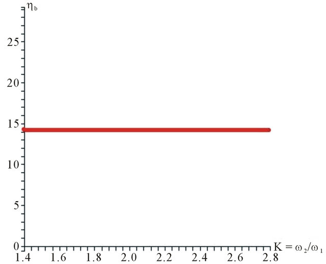
Figure 5. Schematic diagram—the change of quantity of ηb coefficient is shown.
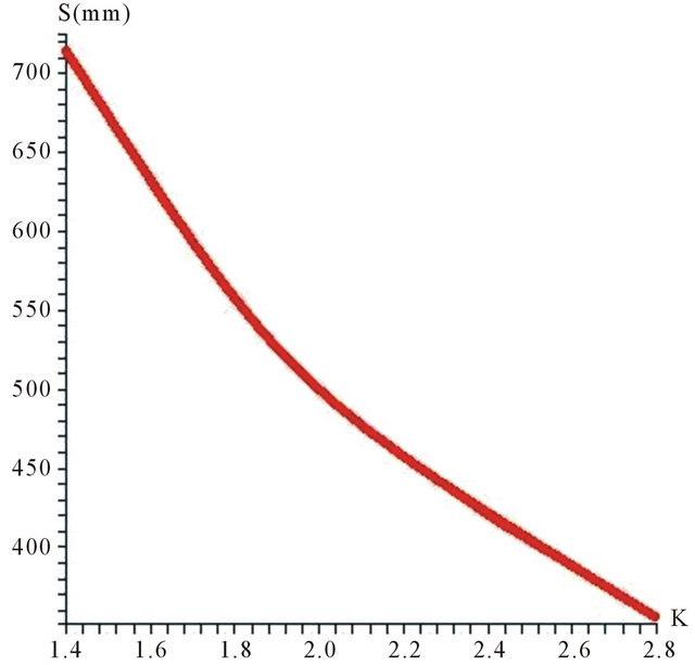
Figure 6. Schematic diagram—change in the length of pickup S for one saw cylinder.
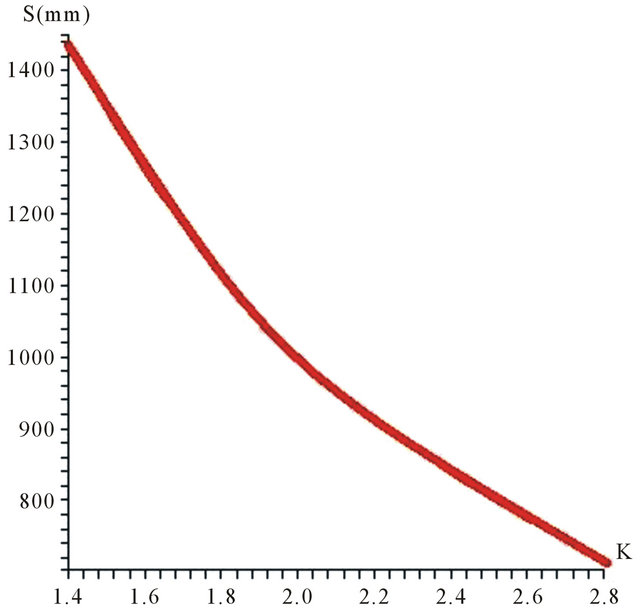
Figure 7. Schematic diagram changing the length of removal S for two saw cylinders.
Table 1. For Figures 1 and 2.
4. Conclusion
The influential coefficiency— is received for brush drum working in normal work regime. When there is an increase of humidity of cotton, it is necessary to increase the influential coefficiency. If it is w = 6%,
 is received. If it is w = 8%, then
  is received.
According to the indication of graph in Figure 5, the productivity and influential coefficiency of our drum has increased to 4 to 5 times as there is  In order to reach for that upper indication, it is necessary to enlarge the diameter of drum and multiply the quantity of brush section.
In Table 1, schedule co efficiency of getting a fiber is modeled considering the number of brush section, the length of way of getting a fiber and indication of angle speed.
Using the indication of Table 1 for Figure 2, the number of optimal brush section is received from 70 to 80 pcs. This creates the opportunity to improve the productivity of work.
In conclusion, we have got the optimal result of the least medium and high level of productivity of work and this is indicated in schedule.
REFERENCES
- A. I. Karimov and J. Ergashev, “The Analysis of Work- ing Parts Cotton Gin,” Journal of the Problem Mechanical Engineers, Vol. 1, 2004, pp. 25-27.
- Sh. M. Azizov and A. I. Karimov, “The Analysis of the Influence of the Clearance between Saw on Length Filament,” Magazine of Tashkent Textile and Industry Institute, Vol. 3, 2004, pp. 38-40.
- G. I. Miroshnechenko, “Bases of Designing of Machines of Primary Processing of Cotton,” Book Theory of Ginning Machine, Moscow, 1972.