World Journal of Mechanics
Vol. 1 No. 3 (2011) , Article ID: 5772 , 13 pages DOI:10.4236/wjm.2011.13013
Combined Effects of Hall Current and Rotation on Unsteady Couette Flow in a Porous Channel
Department of Applied Mathematics, Vidyasagar University, Midnapore, India
Department of Mathematics Narajole Raj College, Narajole, Midnapore West District
Pincode, West Bengal, India
E-mail: jana261171@yahoo.co.in, g_swapan2002@yahoo.com
Received April 1, 2011; revised May 2, 2011; accepted May 11, 2011
Keywords: MHD Couette Flow, Hall Current, Hartmann Number, Rotation Parameter, Reynolds Number And Boundary Layer
ABSTRACT
The combined influences of Hall currents and rotation on the MHD Couette flow of a viscous incompressible electrically conducting fluid between two infinite horizontal parallel porous plates channel in a rotating system in the presence of a uniform transverse magnetic field have been carried out. The solutions for the velocity field as well as shear stresses have been obtained for small time as well as for large times by Laplace transform technique. It is found that for large times the Hall currents accelerates primary flow whereas it retards secondary flow while the rotation retards the primary flow whereas it accelerates the secondary flow. It is also found that the velocity components converge more rapidly for small time solution than the general solution. The asymptotic behavior of the solution is analyzed for small as well as large values of magnetic parameter , rotation parameter
  and Reynolds number
 . It is observed that a thin boundary layer is formed near the moving plate of the channel and the thicknesses of the layer increases with increase in either Hall parameter
  or Reynolds number
  while it decreases with increase in Hartmann number
 . It is interesting to note that for large values of
 , the boundary layer thickness is independent of the rotation parameter.
1. Introduction
In most of the cases, the Hall term is ignored by applying Ohm’s law as it has no marked effect for small magnetic fields. However, to study the effects of strong magnetic fields on the electrically conducting fluid flow, we see that the influence of the electromagnetic force is noticeable and causes anisotropic electrical conductivity in the plasma. This anisotropy in the electrical conductivity of the plasma produces a current known as the Hall current. The Hall effect is important when the magnetic field is strong or when the collision frequency is low, causing the Hall parameter to be significant (Sutton and Sherman [1]). The effects of Hall current on the fluid flow in rotating channels have many engineering applications in flows of laboratory plasmas, in MHD power generation, in MHD accelerators, and in several astrophysical and geophysical situations. Thus, in a rotating system, the effects of Hall current on MHD flow in parallel plate channels have been investigated by many researchers. Chandran et al. [2], Katagiri et al. [3], Ghosh and Pop [4], Ghosh [5], Gubanov and Lunkin [6] and Jana and Datta [7] have studied the MHD Couette flows between two parallel plates channel in a rotating system with Hall effects. Bhaskara and Bathaiah [8] have considered the Hall effects on MHD Couette flow through a porous straight channel. Das et al. [9] have investigated the unsteady MHD Couette flow in a rotating system. The combined effect of free and forced convection on MHD flow in a rotating porous channel have been investigated by Prasad et al. [10]. Mandal and Mandal [11] have studied the effect of Hall current on MHD Couette flow between thick arbitrarily conducting plates in a rotating system. Hall effects on unsteady MHD free and forced convection flow in a porous channel have been studied by Sivaprasad et al. [12].
In the present paper we have studied the combined effects of Hall current and rotation on the MHD Couette flow of a viscous incompressible electrically conducting fluid between two infinite horizontal parallel porous plates channel in a rotating system when one of the plate moving with uniform velocity and the other one held at rest. The solutions for the velocity distributions as well as shear stresses have been obtained for small times as well as for large times by Laplace transform technique. It is found that for large times the primary velocity  increases while the magnitude of the secondary velocity
  decreases with increase in Hall parameter
 . It is also found that for large times the primary velocity decreases while the magnitude of the secondary velocity increases with an increase in rotation parameter
 . Further, the velocity components converge more rapidly for small time solution than the general solution. The asymptotic behavior of the solution is analyzed for small as well as large values of magnetic parameter
 , rotation parameter
  and Reynolds number
 . It is observed that a thin boundary layer is formed near the stationary plate and the thicknesses of the layer increases with increase in either Hall parameter
  or Reynolds number
  while it decreases with increase in Hartmann number
 . It is interesting to note that for large values of
 , the boundary layer thickness is independent of the rotation parameter.
2. Mathematical Formulation and Its Solution
Consider unsteady MHD flow of a viscous incompressible electrically conducting fluid between two infinite parallel porous plates separated by a distance  when both the fluid and channel rotate in unison about an axis normal to the plates with a uniform angular velocity
 . Choose a cartesian co-ordinate system with
  -axis along the lower stationary plate in the direction of the flow, the
  -axis is normal to the plates and the
  -axis perpendicular to
  -plane. A uniform magnetic field
  imposed perpendicular to the plates. The flow within the channel is induced due to the movement of the upper plate
  parallel to itself in
  -direction with a uniform velocity
 . Initially (
 ), fluid as well as plates of the channel are assumed to be at rest. When time
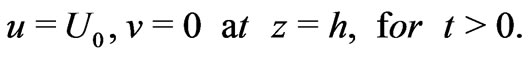
 , the upper plate
  starts to move with uniform velocity
  along
along  - direction in its own plane while the lower plate (z = 0) is kept fixed. Let the velocity components be
  relative to a frame of reference rotating with the fluid. Since the plates of the channel are infinite long
  and
and  directions and are electrically nonconducting all physical quantities, except pressure, will be functions of
  and
and  only. Suction/
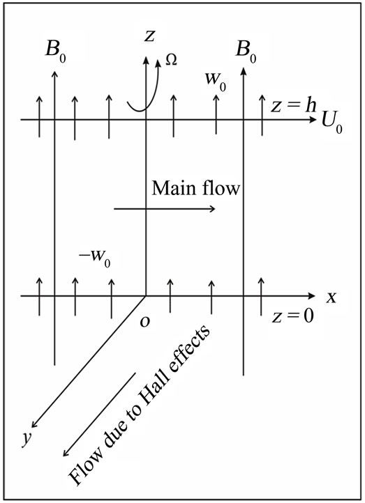
Figure 1. Geometry of the problem.
injection of the fluid takes place through the porous plates of the channel with uniform velocity  which is
  for suction and is
  for injection. The equation of continuity then gives
  everywhere in the fluid.
Neglecting ion-slip and thermoelectric effects, the generalised Ohm’s law for partially ionized gas is [see Cowling[13]]
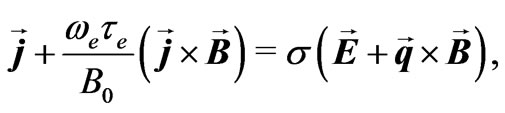 (1)
(1)
where ,
,  ,
,  ,
,  ,
,  ,
,  and
and  are respectively, the magnetic field vector, the electric field vector, the fluid velocity vector, the current density vector, the conductivity of the fluid, the cyclotron frequency and the electron collision time.
We shall assume that the magnetic Reynolds number for the flow is small so that the induced magnetic field can be neglected in comparison to the applied one. This assumption is justified since the magnetic Reynolds number is generally very small for metallic liquids and partially ionized fluids. The solenoidal relation  for the magnetic field gives
  constant
  constant everywhere in the fluid where
 . The equation of conservation of charge
  gives
gives  constant. This constant is zero since
  at the plates which are electrically non-conducting. Thus
  everywhere in the flow. Since the induced magnetic field is neglected, the Maxwell’s equation
 becomes
  which gives
  and
and . This implies that
  constant and
  constant everywhere in the flow.
In view of the above assumption and on taking , Equation (1) gives
 (2)
(2)
 (3)
(3)
where  is the Hall parameter. Solving for
  and
and , we get
 (4)
(4)
 (5)
(5)
On the use of Equations (4) and (5), the equations of motion along  -and
-and  -directions are
 (6)
(6)
 (7)
(7)
 (8)
(8)
where ,
,  and
and  are respectively the fluid density, the kinematic coefficient of viscosity and the modified fluid pressure including centrifugal force.
The initial and the boundary conditions are
 (9)
(9)
Introducing the non-dimensional variables
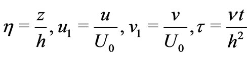 (10)
(10)
Equations (6) and (7) become
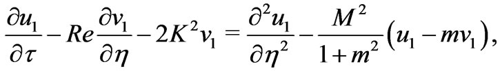 (11)
(11)
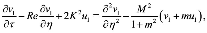 (12)
(12)
where  is the Hartmann number,
  the rotation parameter and
  the Reynolds number.
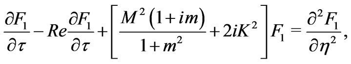
Combing Equations (11) and (12), we have
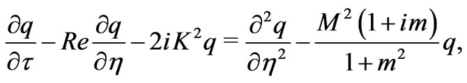 (13)
(13)
where
 (14)
(14)
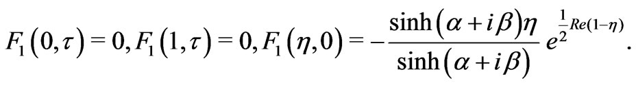
The initial and the boundary conditions for  are
are
 (15)
(15)
 (16)
(16)
2.1. General Solution
For general solution, the method given in Batchelor [15] can be used. The solution of the Equation (13) subject to the conditions (15) and (16) can be written in the following form
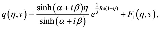 (17)
(17)
where first term on the right hand side is the steady-state solution,  shows the departure from the steady-state and
 (18)
(18)
Now,  satisfies the following differential equation
 (19)
(19)
with
 (20)
(20)
Taking Laplace’s transform of Equation (19), we get
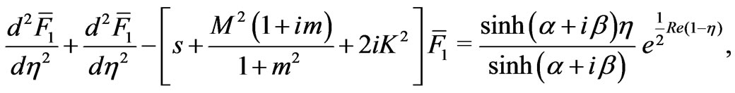 (21)
(21)
where
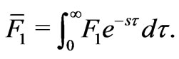 (22)
(22)
The corresponding boundary conditions for  are
are
 (23)
(23)
The solution of the Equation (21) subject to the boundary conditions (23) is
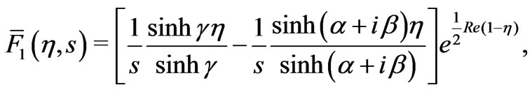 (24)
(24)
where
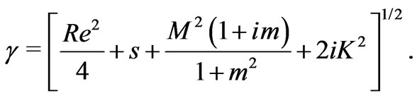 (25)
(25)
Taking inverse Laplace’s transform of the Equation (24), we have
 (26)
(26)
On the use of Equation (17), we have
 (27)
(27)
where
 (28)
(28)
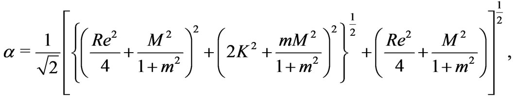
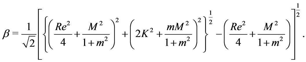
On separating into real and imaginary parts and using Equation (10), we get
 (29)
(29)
 (30)
(30)
where

 (31)
(31)
The solutions given by Equations (29) and (30) exist for both  (corresponding to
  for the blowing at the plates) and
  (corresponding to
  for the suction at the plates). If
  and
and , then the above Equations (29) and (30) are identical with Equations (26) and (27) of Das et al. [9].
2.2. Solutions for Small Time
Following Carslaw and Jaegar [16], for small time, the solution of (13) subject to the boundary conditions (15) and (16) is obtained by Laplace transform technique in the following form
 (32)
(32)
where
 (33)
(33)
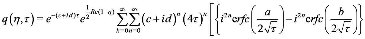
The solution (32) can be written as
 (34)
(34)
where
 (35)
(35)
On separating into real and imaginary parts and using Equation (14), we get the velocity distributions for the primary and the secondary flow as

 (36)
(36)

 (37)
(37)
The Equations (36) and (37) describe the fluid velocities for small times. If  and
and , the Equations (36) and (37) coincide with Equations (17) and (18) of Das et al. [9].
3. Results and Discussion
To study the effects of rotation, suction/blowing and Hall parameter on the velocity distributions we have presented the non-dimensional velocity components  and
and  against
  in Figures 2-6 for various values of magnetic parameter
 , the rotation parameter
 , Hall parameter
 , Reynolds number
  and time
 . It is seen from Figure 2 that both the primary velocity
  and the magnitude of the secondary velocity
  increases with an increase in squared-Hartmann number
  as expected since the magnetic field has a retarding influence on the flow. Figure 3 reveals that the primary velocity
  decreases with increase in
 . On the other hand, the magnitude of the secondary velocity
  increases with an increase in
 . It is observed from Figure 4 that both the primary velocity
  and the magnitude of the secondary velocity
  increase with an increase in Hall parameter
 . Figure 5 shows that the primary velocity
  increases while the magnitude of the secondary velocity
  decreases with an increase in Reynolds number
 . It is observed from Figure 6 that both the primary velocity
  and the magnitude of the secondary velocity
  increase with an increase in times
 . For small values of time, we have drawn the velocity components
  and
and  on using the solution given by Equations (36) and (37) and the general solution given by Equations (29) and (30) in Figures 7 and 8. It is seen that the solution for small time given by the Equations (36) and
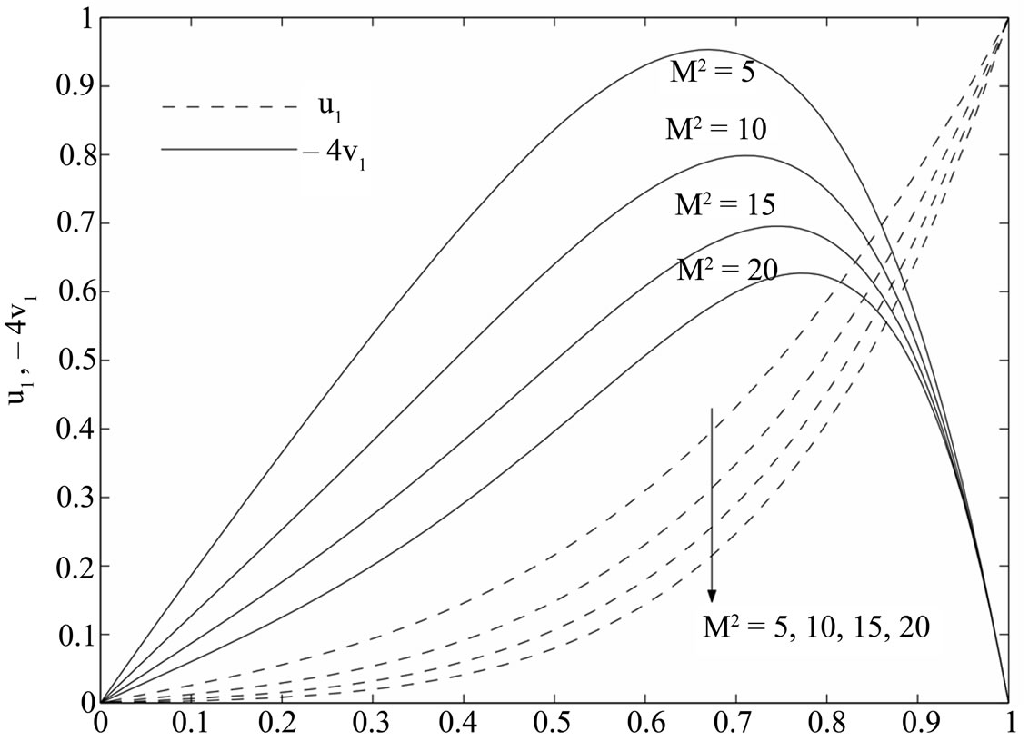
Figure 2. Variations of  and
and  for
for .
.
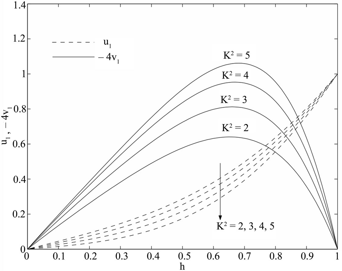
Figure 3. Variations of  and
and  for
for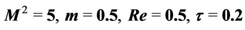 .
.
(37) converges more rapidly than the general solution given by (29) and (30). Hence, we conclude that for small times, the numerical values of the velocity components can be evaluated from the Equations (36)
and (37) instead of Equations (29) and (30).
For large time, the non-dimensional shear stresses due to the primary and the secondary flows at the stationary plate  are given by
 (38)
(38)
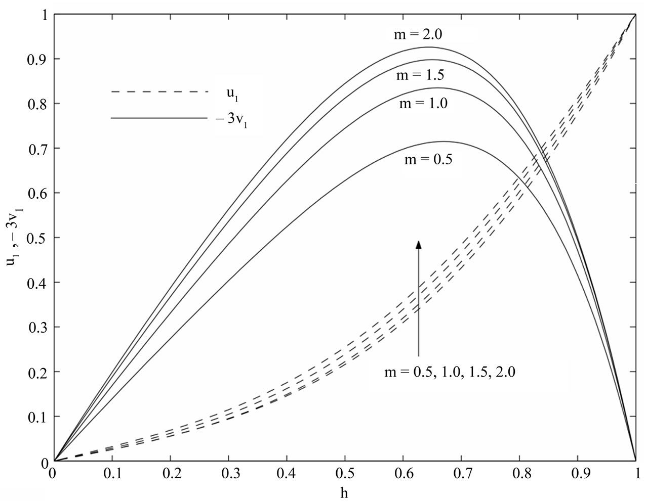
Figure 4. Variations of  and
and  for
for .
.
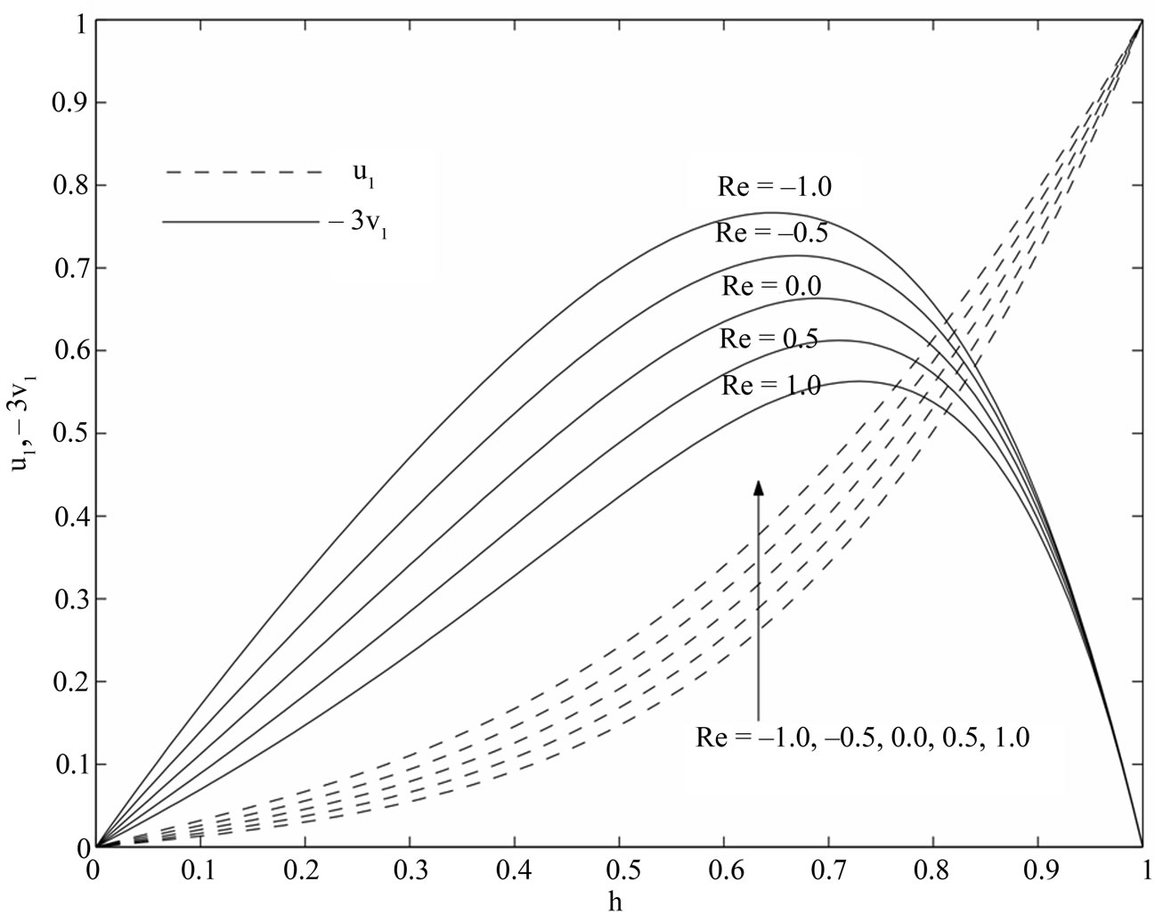
Figure 5. Variations of  and
and  for
for .
.
On separating real and imaginary parts, we get the shear stress components due to the primary and secondary flows at the stationary plate ( ) as
) as
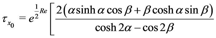
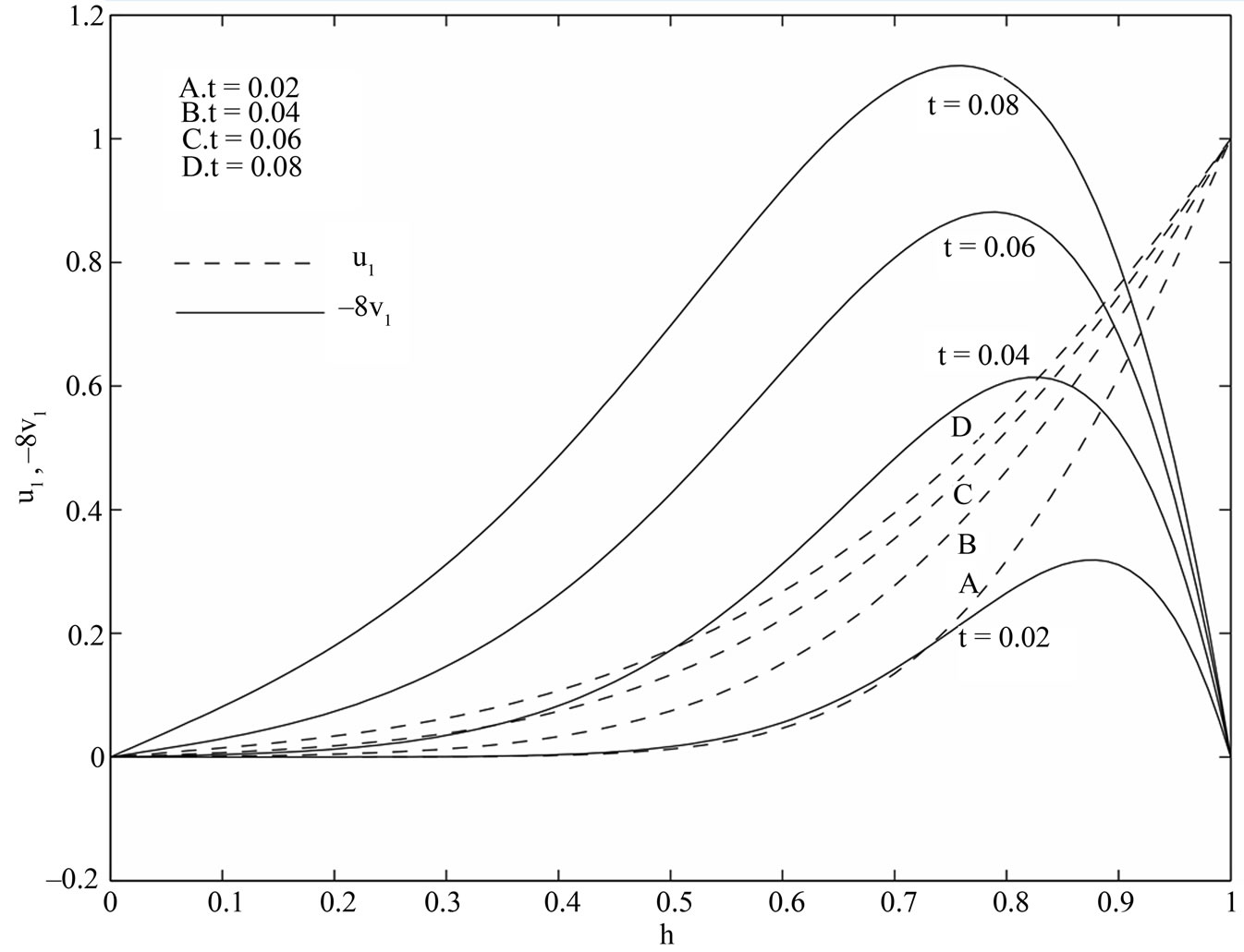
Figure 6. Variations of  and
and  for
for .
.
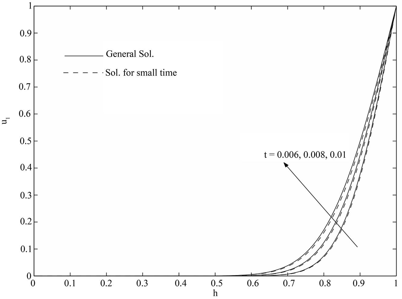
Figure 7. Variations of  for the general solution and small time solution with
 .
.
 (39)
(39)
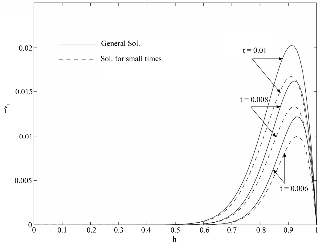
Figure 8. Variations of  for the general solution and small time solution with
 .
.
 (40)
(40)
The numerical values of  and
and  are presented in Figs.9-12 against Hall parameter
  for various values of
 ,
,  ,
,  and
and . It is seen from Figure 9 that both the shear stress
  and the magnitude of the shear stress
  decrease with increase in
  when
when  is fixed while
  first decreases and reaches minimum and then increases and the magnitude of
  increases with an increase in
  when
when  is fixed. Figure 10 displays that both the shear stress
  and the magnitude of the shear stress
  decrease with increase in
  when
when  is fixed. It is seen from Figure 11 that both the shear stress
  and the magnitude of
  increase with an increase in
  when
when  is fixed while
  first decreases and reaches minimum and then increases and the magnitude of
  first increases and reaches maximum and then decreases with an increase in
  when
when  is fixed. It is also seen from Figure 12 that for fixed values of time
 ,
,  first decreases and reaches minimum and then increases and the magnitude of
  increases with an increase in
 . On the other hand, for fixed values of
 ,
,  decreases and the magnitude of
  increases with an increase in time
 .
.
For small times, the non-dimensional shear stresses due to the primary and secondary flows at the stationary plate ( ) are given by
 (41)
(41)
where
 (42)
(42)
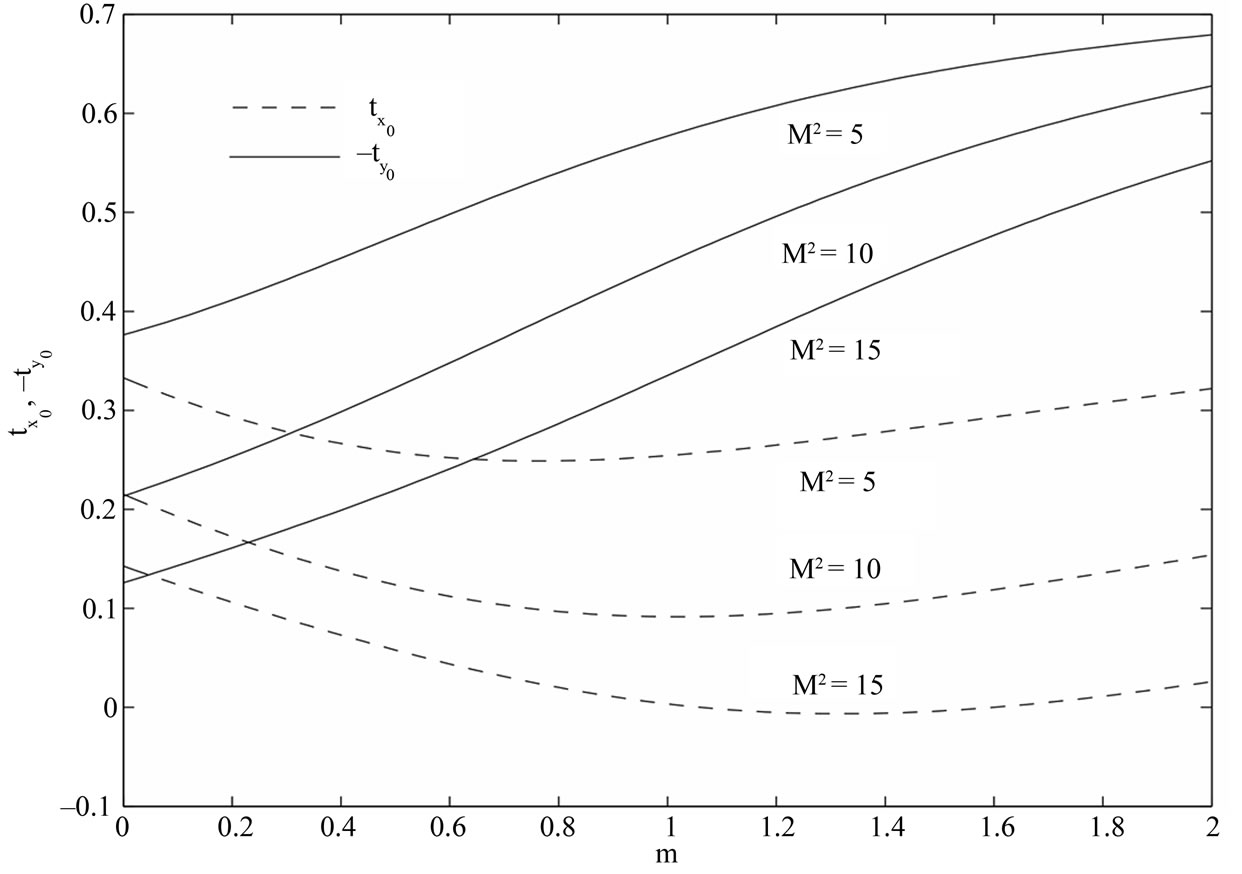
Figure 9. Variations of  and
and  for
for .
.
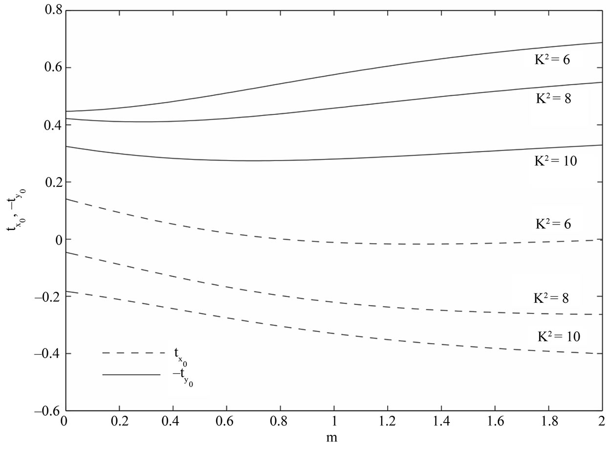
Figure 10. Variations of  and
and  for
for .
.
On separating real and imaginary parts, we get the shear stress components due to the primary and secondary flow as


 (43)
(43)
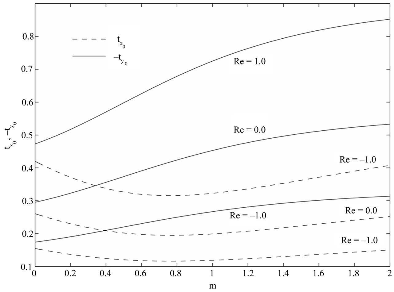
Figure 11. Variations of  and
and  for
for .
.
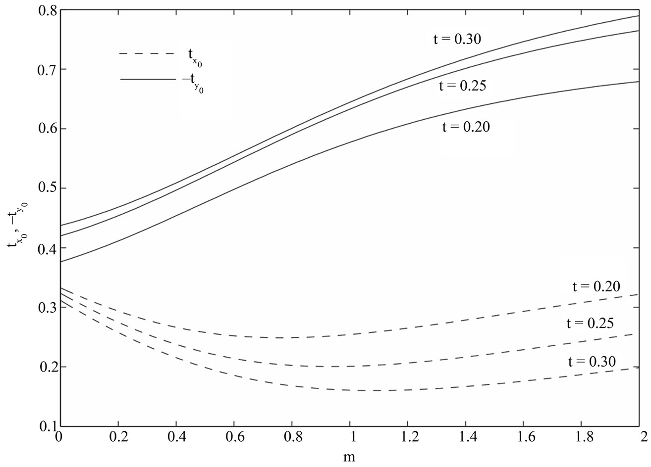
Figure 12. Variations of  and
and  for
for .
.
We shall now discuss the asymptotic behavior of the solutions (29) and (30) for small and large values of ,
,  and
and :
:
Case(i): When ,
,  and
and .
.
When  is large,
  and
and  are of small order of magnitude, the flow becomes boundary layer type. For the boundary layer flow near the upper plate
 , introducing the boundary layer coordinate
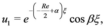
 , we obtain the velocity distributions from (29) and (30) as
 (44)
(44)
 (45)
(45)
where
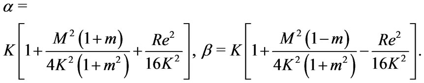 (46)
(46)
It is evident from Equations (44)and (45) that there arises a single-deck boundary layer of thickness of order
 near the moving plate (
 ) of the channel where
  is given by (46). The thickness of this boundary layer increases with increase in either Hall parameter
  or rotation parameter
  since
since  decreases with increase in either
  or
or . On the other hand, it decreases with increase in either Hartmann number
  or
or  as
as  increases with increase in either
  or
or .
.
Case(ii): When ,
,  and
and .
.
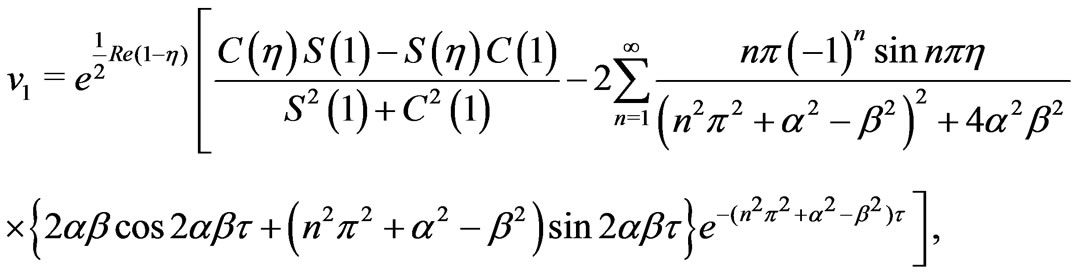
In this case, the velocity distributions are obtained from the Equations (29) and (30) as
 (47)
(47)
 (48)
(48)
where
 (49)
(49)
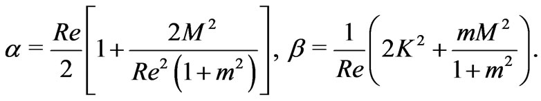
The Equations (47) and (48) reveal that there appears a single-decker boundary layer of thickness of the order
 adjacent to the moving plate (
 )
)
of the channel where  is given by (49). The thicknesses of the layer increases with increase in either Hall parameter
  or Reynolds number
  while it decreases with increase in Hartmann number
 . It is interesting to note that for large values of
 , the boundary layer thickness is independent of the rotation parameter.
Case(iii): When ,
,  and
and .
.
In this case, Equations (28) and (29) become
 (50)
(50)
 (51)
(51)
where
 (52)
(52)
It is seen from Equations (50) and (51) that there exists a single-deck boundary layer of thickness of order
 where
where  is given by (52). It is seen that the thickness of this boundary layer increases with increase in either Hall parameter
  or Reynolds number
  since
since  decreases with increase in either
  or
or . On the other hand, it decreases with increase in squared-Hartmann number
  as
as  increases with increase in
 .
.
4. Conclusions
To study the effects of Hall current, rotation, magnetic field, suction/injection and time on the flow field, the primary and secondary velocities and shear stress at the stationary plate due to the primary and secondary flows are depicted graphically for various values of ,
,  ,
,  ,
,  and
and . It is found that for large time the primary velocity
  increases while the magnitude of the secondary velocity decreases
  with increase in Hall parameter
 . It is also found that for large time the primary velocity
  decreases while the magnitude of the secondary velocity
  increases with an increase in rotation parameter
 . It is also found that the solution for small time converges more rapidly than the general solution. The asymptotic behavior of the solution is analyzed for small as well as large values of magnetic parameter
 , rotation parameter
  and Reynolds number
 . It is observed that a thin boundary layer is formed near the stationary plate and the thicknesses of the layer increases with increase in either Hall parameter
  or Reynolds number
  while it decreases with increase in Hartmann number
 . It is interesting to note that for large values of
 , the boundary layer thickness is independent of the rotation parameter. The expression for the shear stress at the stationary plate due to the primary and secondary flows is obtained in both the cases.
REFERENCES
- G. W. Sutton and A. Sherman, “Engineering Magnetohydrodynamics,” McGraw-Hill, New York, 1965.
- P. Chandran, N. C. Sacheti and A. K. Singh, “Effect of Rotation on Unsteady Hydromagnetic Couette Flow,” Astrophysics and Space Science, Vol. 202, No. 1, 1993, pp. 1-10. doi:10.1007/BF00626910
- G. S. Seth and Md. S. Ansari, “Magnetohydrodynamic Convective Flow in a Rotating Channel with Hall Effects,” International Journal of Theoretical and Applied Mechanics, Vol. 4, No. 2, 2009, pp. 205-222.
- S. K. Ghosh and I. Pop, “Hall Effects on MHD Plasma Couette Flow in a Rotating Environmen,” Interantional Journal of Applied Mechanics and Engineering, Vol. 9, No. 2, 2004, pp. 293-305.
- S. K. Ghosh, “Effects of Hall Current on MHD Couette Flow in a Rotating System with Arbitrary Magnetic Field,” Czechoslovak Journal of Physics, Vol. 52, No. 1, 2002, pp. 51-63. doi:10.1023/A:1013913730086
- A. I Gubanov and P. T. Lunkin, “Couette Flow of an Electrically Conducting Fluid between Two Parallel Plates with Hall Effects,” Soviet Physics-Technical Physics, Vol. 5, 1961, p. 984.
- R. N. Jana and N. Datta, “Hall Effects on MHD Couette Flow in a Rotating System,” Czechoslovak Journal of Physics, Vol. B30, 1980, p. 659.
- N. B. Reddy and D. Bathaiah, “Hall Effects on MHD Couette Flow through a Porous Straight Channe,” Defense Science Journal, Vol. 32, 1982, pp. 313-326.
- S. Das, S. L. Maji, M. Guria and R. N. Jana, “Unsteady MHD Couette Flow in a Rotating System,” Mathematical and Computer Modelling, Vol. 50, 2009, pp. 1211-1217. doi:10.1016/j.mcm.2009.05.036
- D. R. V. Prasad Rao, D. V. Krishna and L. Debnath, “Combined Effect of Free and Forced Convection on MHD Flow in a Rotating Porous Channe,” International Journal of Mathematics and Mathematical Sciences, Vol. 5, 1982, pp. 165-182. doi:10.1155/S0161171282000167
- G. Mandal and K. K. Mandal, “Effect of Hall Current on MHD Couette Flow between Thick Arbitrarily Conducting Plates in a Rotating System”, Journal of the Physical Society of Japan, Vol. 52, 1983, pp. 470-477. doi:10.1143/JPSJ.52.470
- R. Sivaprasad, D. R. V. P. Rao and D. V. Krishna, “Hall Effects on Unsteady MHD Free and Forced Convection Flow in a Porous Channel,” Indian Journal of Pure and Applied Mathematics, Vol. 19, No. 7, 1988, pp. 688-696.
- T. G. Cowling, “Magnetohydrodynamics,” Interscience, New York, 1957.
- S. I. Pai, “Magnetogasdynamics and Plasma Dynamics,” Springer-Verlag, Viena; Prentice Hall, Englewood cliffs, 1962.
- G. K. Batchelor, An Introduction to Fluid Dynamics, Ist ed., Cambridge Press, Cambridge, U. K., 1967, p. 200.
- H. S. Carslaw and J. C. Jaeger, “Conduction of Heat in Solids,” Oxford University Press, Oxford, 1959.