Journal of Sensor Technology
Vol.2 No.4(2012), Article ID:25606,11 pages DOI:10.4236/jst.2012.24026
Crayfish Robot That Generates Flow Field to Enhance Chemical Reception
Graduate School of Bio-Applications and Systems Engineering, Tokyo University of Agriculture and Technology, Tokyo, Japan
Email: *h_ishida@cc.tuat.ac.jp
Received October 3, 2012; revised November 4, 2012; accepted December 5, 2012
Keywords: Active Sensing; Underwater Robot; Chemical Sensor; Crayfish
ABSTRACT
This paper describes a wheeled underwater robot developed for locating chemical sources autonomously under stagnant flow conditions. In still water, the released chemical stays in the immediate vicinity of the source location. The search for chemical sources under such conditions is extremely laborious since the presence of a chemical source cannot be detected from a distant place. The chemical sensors on the robot show no response unless a chemical substance released from the source arrives at the sensors. Crayfish in search of food are known to actively generate water currents by waving their small appendages with a fan-like shape. It is considered that the generated water currents help their olfactory search. The smell of food is carried to their olfactory organs from the surroundings by the generated flow, and then is perceived. The robot presented in this paper employs arms mimicking the maxillipeds of a crayfish to generate water currents and to draw chemicals to its sensors. By waving the arms vertically, a three-dimensional flow field is generated and water samples are drawn from a wide angular range. The direction of a chemical source can be determined by comparing the responses of four laterally aligned electrochemical sensors. Experimental results show that the flow field generated by the maxilliped arms is more effective in collecting chemical samples onto the sensors than that generated by a pump. The robot equipped with the maxilliped arms can detect the presence of a chemical source even if the source is placed off the trajectory of the robot.
1. Introduction
Many aquatic animals rely on their olfaction when searching for food [1-3]. For example, sharks are famous for their keen sense of smell, and are known to find food by tracking odor plumes. When they perceive a smell of food, they proceed in the upstream direction [1]. Since molecular diffusion of chemical substances into water is extremely slow (only 5 mm in 1 h) [4], fluid flow is the main force for the dispersal of chemical molecules in most underwater environments. Therefore, upstream progress upon detection of a chemical substance generally brings a searcher closer to the chemical source. This type of behavior is termed odor-gated rheotaxis [3], and is known to be the behavioral basis of variety of animals [1]. Underwater robots with such chemical sensing capabilities could be applied to search for chemical sources. There are places in the sea where hazardous or toxic chemicals, e.g., chemical weapons [5] and unexploded ordnance [6], are left or dumped. Chemical leakage from undersea wreckage [7] also causes serious trouble to the local people. Although these chemicals must be localized and removed for the protection of the marine environment, to find them out is an extremely laborious task for human divers. Underwater robots can accomplish the chemical search more effectively if appropriate sensors and search algorithms are provided.
Olfactory signals spread in the environment by diffusion and advection of odor molecules [8]. Animals perceive odors when the odor molecules actually reach the surfaces of the olfactory receptor cells. In order to achieve sensitive odor detection, many animals make efforts to collect odor molecules effectively onto the olfactory receptor cells [9]. It is expected that mimicking such odor collection behavior will lead to great improvements in chemical detection and chemical localization abilities of the robots [9]. In rivers and tides, odor molecules are transported by water flow and form odor plumes. Therefore, the smell of food can be perceived at far downstream locations, and animals can employ odor-gated rheotactic strategies to search for food. However, there are many places where the flow velocity is extremely small. Under such stagnant flow conditions, the released odor molecules stay in the immediate vicinity of the source. Therefore, spontaneous arrival of odor molecules on the olfactory receptor cells cannot be expected. Olfactory search for food becomes particularly laborious since no smell can be perceived even if the food is only a few centimeters away. In rivers and tides, temporal variations of the chemical distribution caused by turbulence of the flow and fluctuations of the flow direction make the olfactory search an awkward task. A chemical distribution developed under stagnant flow conditions is more stable, and therefore, fluctuations in the chemical signals perceived by animals are significantly smaller. However, the limited dispersal of the odorants poses a tough challenge.
Nevertheless, crayfish prefer to live in still water, e.g., at the bottom of a lake or a pond. Even though crayfish are known to show upstream plume tracking behavior in strong water flow [3], they can also search for food by using their olfaction even under stagnant flow conditions. Their fan organs (exopodites of maxillipeds) are considered to help in collecting odor molecules effectively [4, 10]. A crayfish has three pairs of maxillipeds around the mouth opening below the major chemoreceptor organs (antennules), as shown in Figure 1. Feathered hairs extending on both sides of the distal part of the exopodite of each maxilliped form a fan-like shape. By waving the feathered appendages, a crayfish actively generates two outgoing water jets. Upward water currents directed to the antennules and incoming flow converging to the maxillipeds are induced because of fluid entrainment by the jets. As shown in Figure 2(a), the induced flow brings odor samples from distant places to the chemoreceptors on the antennules, and thus, the smell of the food is perceived. Inactivation of the fan organs of crayfish results in a significant decrease in their success in finding an odor source, which suggests the importance of the actively generated water currents for the success in olfactory search under the stagnant flow conditions [10].
The goal of this research project is to develop an underwater robot that can autonomously locate chemical sources. Toward successful applications of such robots in real environments, various technological challenges need to be overcome. They include the development of autonomous underwater vehicle platforms and appropriate chemical sensors, as well as devising effective search strategies and optimizing the sensor configurations. Our focus is on the latter two issues. Two underwater robots with chemical plume tracking capabilities have been reported so far in the literature. Both of them are based on the rheotactic strategies, assuming the existence of sufficiently strong water flow and chemical plumes with well-defined shapes [11,12]. In contrast, here we report a crayfish robot designed to search for chemical sources under stagnant flow conditions. The robot is not only equipped with an array of chemical sensors, but also with
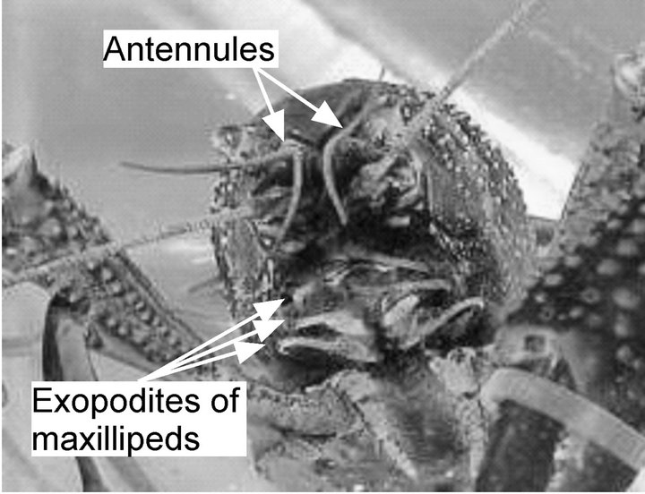
Figure 1. Crayfish, Procambarus clarkii.
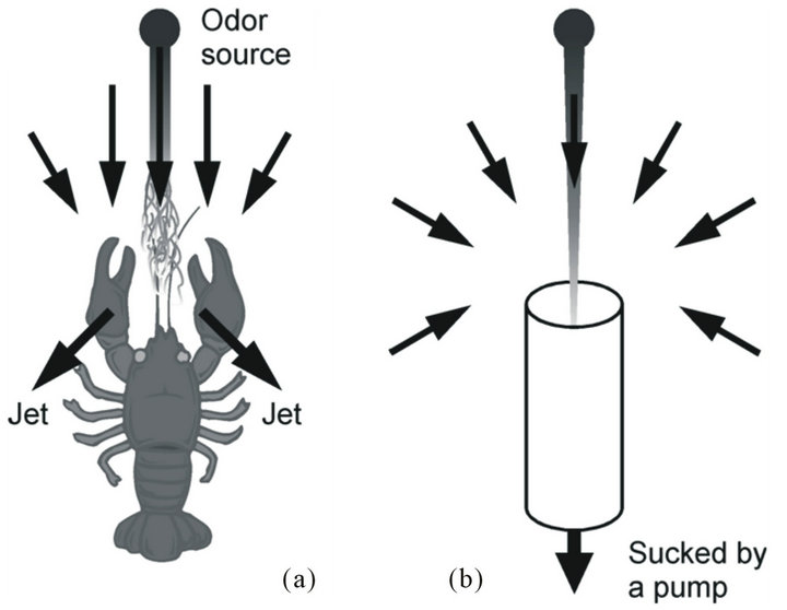
Figure 2. Flow fields generated by (a) a crayfish waving the maxillipeds and (b) a suction pump.
a flow generator to enhance chemical reception by drawing surrounding water samples to the sensors. In our previous work, the underwater robotic system with a suction pump was developed [13]. The newly developed autonomous mobile robot described in this paper is equipped with a pair of arms mimicking the maxillipeds of a crayfish. Experimental results are presented to show that the flow field generated by waving maxilliped arms is more effective in enhancing chemical reception than that generated by a pump. Although the rheotactic strategy for chemical source localization is not applicable under stagnant water conditions, the proposed crayfish robot can locate a chemical source using a chemotactic search strategy.
The structure of the rest of the paper is as follows. In Section 2, descriptions of the crayfish robot and its prototypes are provided. In Section 3, experimental results on testing different ways of waving the maxilliped arms are presented. In Section 4, comparison is made between the flow fields generated by the maxilliped arms and a pump. In Sections 5 and 6, results of experiments on chemical source localization are summarized. Section 7 concludes the paper.
2. Experimental
2.1. Crayfish Robot
The detailed analysis of the flow patterns generated by crayfish revealed their high efficiency in collecting odor samples [10]. If water is sucked through a pipe using a pump as in our previous work [13], the inlet opening of the pipe can be regarded as a point sink [10]. In this case, a spherically symmetric flow field is generated, as shown in Figure 2(b). The flow velocity decreases with the inverse square of the distance [10]. In contrast, the inflow generated by fluid entrainment of jets decays more slowly. It was experimentally shown that the velocity decay of the inflow generated by a crayfish is inversely proportional to the distance [10].
Figure 3 shows our crayfish robot (350 mm long). The head part of the robot is equipped with arms mimicking the crayfish maxillipeds. To generate unidirectional water currents, a crayfish actively flexes and extends the feathered hairs of the maxillipeds synchronously with the waving motion of the maxillipeds [4]. To make the arm wave in a similar way, a plastic fan (8 mm × 6 mm) was attached on the tip of each stainless-steel maxilliped arm using an elastic hinge, as shown in Figure 4. During the power stroke, the fan is kept extended by the support of the arm as shown in Figure 4(a), and water current is generated. During the recovery stroke, the fan is folded as shown in Figure 4(b) owing to the fluid resistance. Thus, generation of a water current in the opposite direction is minimized. The size of the plastic fan is roughly twice as large as the feathered tip of a crayfish maxilliped.
As shown in Figure 5, a pair of maxilliped arms are placed on the left and right sides of an array of sensing electrodes of the electrochemical sensors. The distance between the left and right arms is 50 mm. Each maxilliped arm is driven by a parallel crank mechanism and a
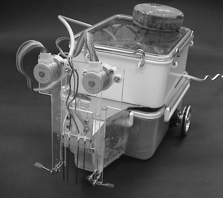
Figure 3. Crayfish robot.
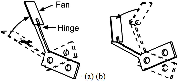
Figure 4. (a) During the upward stroke of a maxilliped arm, the fan acts like a paddle; (b) During the recovery stroke, the hinge is folded due to the drag by water.
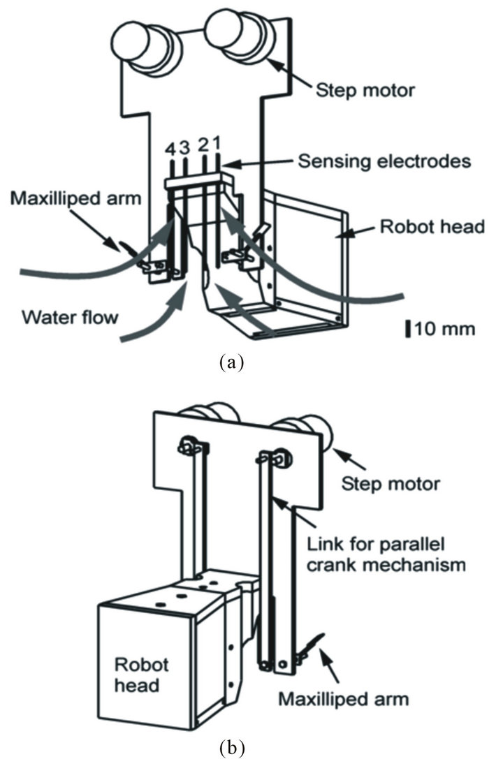
Figure 5. Head part of the crayfish robot; (a) Front view; (b) Rear view.
step motor (SPG20-298, Copal Electronics Corp.) placed above the water surface. The maxilliped arms are waved at 5 Hz by adjusting the speeds of the step motors using a microcontroller (PIC12F683, Microchip). This frequency was chosen to be the same as the frequency at which crayfish wave their maxillipeds [4]. By waving the maxilliped arms vertically by 90˚, the crayfish robot generates upward water currents. Consequently, inflow that draws water samples to the sensing electrodes from the surroundings is induced as shown in Figure 5(a).
The body of the robot was made using a waterproof plastic container. A silicone rubber seal placed between the upper rim of the container body and its detachable lid prevents water from seeping in. Commercially available rotary shaft seals (Turcon Roto Variseal, Trelleborg Sealing Solutions) keep water from entering through gaps between the shafts of the driving wheels and the sockets. A weight was loaded to prevent the robot from floating up during the experiments.
The robot is equipped with two independent wheels driven by DC geared motors (TG47C VM-230-KBED, Tsukasa Electric Co.). An EyeBot (JOKER Robotics) is employed as a main controller of the robot. A Motorola 68332 microcontroller operated at 25 MHz processes the received sensor responses and sends the control signals to the motors. The feedback signals from the rotary encoders on the DC motors are used for odometry. The sensor responses and the odometry data are sent to an external PC through serial communication in order to record the data for detailed off-line analysis. A lithiumion rechargeable battery with a capacity of 1500 mAh (NP-400, Konica Minolta Holdings, Inc.) can supply electric power to the robot up to 90 min.
Amperometric electrochemical sensors are used to detect chemical substances. Four carbon working electrodes with a diameter of 0.9 mm are placed at the front part of the robot head. These working electrodes share a silver reference electrode and a stainless-steel counter electrode, which are placed on the bottom of the robot head. A potentiostat circuit controls the voltage between the working electrodes and the reference electrode at a certain set point (0.7 - 0.8 V). The current generated by oxidation or reduction of a target chemical at each working electrode is converted to a voltage output. A dedicated microcontroller (PIC16F690, Microchip) measures the four voltage outputs of the potentiostat circuit, and sends the voltage values to the EyeBot controller. The sensing electrodes are numbered from the left to the right of the robot as shown in Figure 5(a).
When in search of a chemical source, the robot examines the existence of a chemical substance in the collected water samples, and starts to move if the response of any of the four sensors exceeds a predefined threshold. The robot proceeds in the direction of the sensor with the largest response. When the largest signal is obtained from sensor 1, the robot turns counterclockwise by 8˚ and then moves forward by 6 mm. When the output of sensor 2 is the largest, the turning angle is reduced to 4˚. If sensor 3 or 4 shows the highest response, the robot moves in a similar way except that the turn is made in the clockwise direction. It was sometimes observed that a water sample drawn to the sensor stayed on the carbon working electrode even after the forward movement of the robot. To wait for the water samples around the sensors to be replaced, the robot pauses for one second after each forward movement. The direction determination is performed based on the sensor output values measured after the pause.
2.2. Prototype Chemical Sensing Systems
Before the fabrication of the crayfish robot described in the previous section, the chemical sample collection efficiency of the maxilliped arms was investigated using prototype chemical sensing systems shown in Figure 6. Each of these systems is equipped with a pair of maxilliped arms and four electrochemical sensors on a robot head with the same shape. Crayfish can generate various flow fields by changing the waving direction of the maxillipeds [4]. In this work, two fundamental waving patterns, vertical and horizontal waving, were tested for reproduction of the flow field generated by a crayfish. Figure 6(a) shows the sensing system that waves the arms vertically. The maxilliped arms are placed on both sides of the sensing electrodes, and are driven by step motors and rack gears. Figure 6(b) shows the system that waves the arms horizontally. Each maxilliped arm is directly attached on the shaft of a step motor, and is placed behind the sensing electrodes.
To use a pump is probably the simplest and most widely used way for robots to generate water currents. To show the advantage of the maxilliped arms in the effectiveness on collecting water samples on the sensors, the water currents generated by a pump were compared in terms of chemical reception at the sensors with those generated by the maxilliped arms. As shown in Figure 7, a robot head equipped with a suction opening connected to a pump was prepared for this purpose. The shape of the robot head is same as that equipped with the maxilliped arms. A Plexiglas pipe with an inner diameter of 16 mm goes through the head, and the water is sucked from the opening placed behind the working electrodes of the electrochemical sensors.
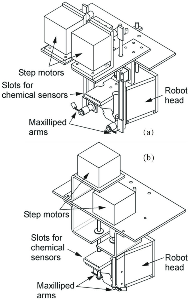
Figure 6. Prototype chemical sensing systems with maxilliped arms waved (a) vertically and (b) horizontally.
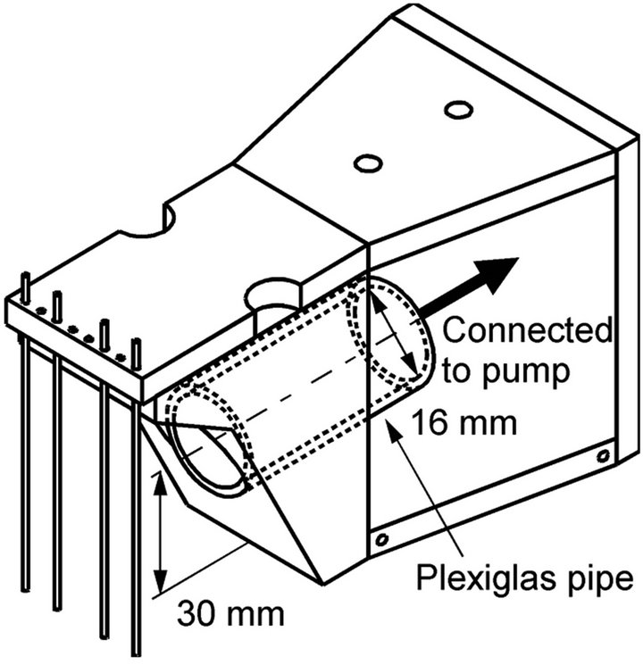
Figure 7. Robot head with a suction opening connected to a pump.
2.3. Experimental Method
In the experiments on chemical source localization, the robot tried to detect a chemical substance in a small water pool (1300 mm × 800 mm) shown in Figure 8 unless otherwise specified. The pool was filled with salt water up to a depth of 100 mm. The step motors used for waving the maxilliped arms are the only non-waterproof parts of the crayfish robot. With the water depth of 100 mm, the sensing electrodes are fully immersed in the water while the water surface is maintained below the step motors. Aqueous solution of ascorbic acid with a concentration of 10 mm was used as the detection target because of its ease in electrochemical detection [14]. A small amount of fluorescent dye (10 mg/l of rhodamine 6G) was added to the ascorbic acid solution to enable the visual observation of the ascorbic acid distribution. The three-dimensional movement of the released chemical substance was observed in detail for the prototype sensing systems. The robot head was placed in a water tank (500 mm wide, 500 mm deep, and 155 mm high) made of transparent Plexiglas. The depth of salt water was set to 100 mm as in the other experiments.
Since a certain amount of supporting electrolyte is required for proper operation of the electrochemical sensors, salt (sodium chloride) was added to the background water and the ascorbic acid solution. The concentration of salt was adjusted to be in the range of 0.1 M to 0.485 M. The concentration of 0.485 M corresponds to the salinity of seawater, and was chosen in view of future applications of the robot in marine environments. The water pool holds 104 liters of water, and 2.9 kg of salt is required to attain the same salinity as the seawater. For the repeated experiments in the water pool, the concentration of salt was decreased to 0.1 M to reduce the consumption of salt. Cyclic voltammograms measured in 1 mM ascorbic acid solution with various salinities show that the decrease in the salt concentration to 0.1 M has no effect on the response of the carbon electrode sensor to ascorbic acid.
Figure 9 shows the coordinate system used to describe the location of a chemical source with respect to the robot head. The origin of the coordinate system is set to the center of the four sensing electrodes. The positive x-axis points forward, and the positive y-axis points to the left. A stainless-steel tube releasing ascorbic acid solution at a flow rate of 1 ml/min was used as a chemical source. The tip of the tube was pointed upward and placed at the same height as the maxilliped arms of the robot. In the experiments, the ascorbic acid solution was released from various locations around the robot head by changing the position of the tube. The chemical release was started when waving of the maxilliped arms was initiated.
3. Flow Fields Generated by Maxilliped Arms
Figures 10 and 11 show the typical sensor responses measured for the prototype chemical sensing system shown in Figure 6(a). Vertical waving of the maxilliped arms was started at the same time as the start of the chemical release, and the responses of the amperometric electrochemical
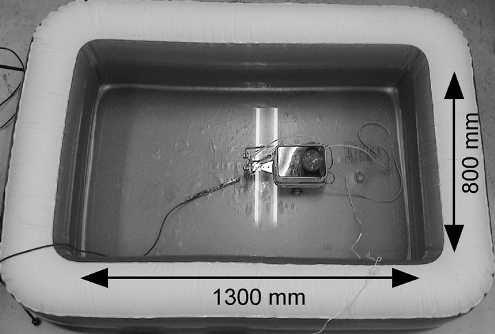
Figure 8. Water pool in which the robot was tested.
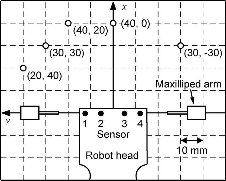
Figure 9. Coordinate system and representative locations for a chemical source (top view).
sensors were recorded. Figure 10 shows the sensor responses when the source was placed at (x, y) = (25 mm, 35 mm). The sensor response values began to increase at 8 s after starting to wave the maxilliped arms. It was confirmed from the visual observation that the chemical substance was carried by the actively generated water currents and drawn to the robot head. The timing at which the sensors began to respond agreed with the timing at which the front of the dye blob released from the chemical source reached the sensing electrodes. If the maxilliped arms were not activated, no sensor response was observed for at least several hundreds of seconds.
In the experiment shown in Figure 10, the source was placed at the left front of the robot head. Since sensors 1 and 2 were closer to the source, ascorbic acid solution drawn from the source mostly reached those sensors before completely dispersed by the maxilliped arms. Consequently, the responses of these sensors were larger than the others. On the contrary, when the source was placed at right front of the robot, (x, y) = (40 mm, −30 mm), sensors 3 and 4 showed larger responses than the others, as shown in Figure 11. The visual observation also con-
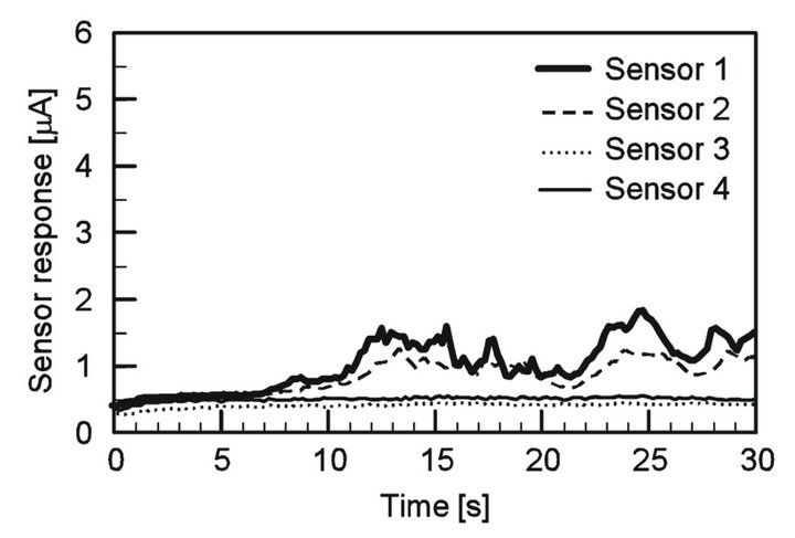
Figure 10. Sensor responses when the chemical source was placed at the left front of the prototype sensing system with the maxilliped arms waved vertically. The ascorbic acid solution released from the source was drawn to the robot, and the sensors started to respond at 8 s after the start of the chemical release.

Figure 11. Sensor responses when the chemical source was placed at the right front of the prototype sensing system with the maxilliped arms waved vertically. Sensors 3 and 4 showed larger responses than the others since they were closer to the source.
firmed that, depending on the direction of the chemical source, the patch of the released chemical is drawn to specific sensors. The direction of the chemical source can be determined by comparing the responses of the four sensing electrodes.
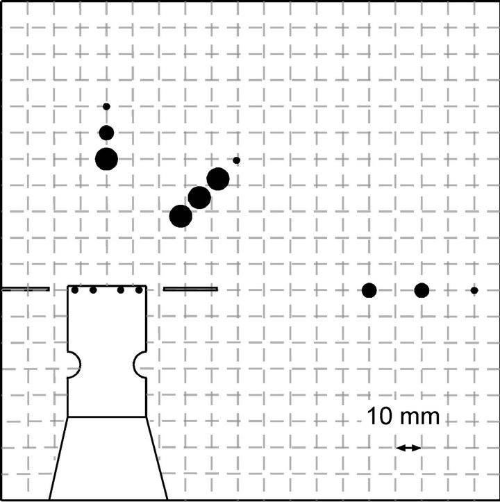
In Figure 12, the flow fields generated by the two prototype sensing systems are compared for the range of drawing a chemical substance to the sensors. The sensor response measurement was carried out only for the source locations on the right side of the robot head since the symmetry of the generated flow fields were confirmed in the preliminary experiments for both prototype systems. The chemical source was placed at various distances from the robot head in three directions, i.e., the front, right front, and right side. The closed circles in Figure 12 indicate the points at which the chemical was released. Their sizes show the rate of chemical detection defined as the rate of time in which the response of at least one sensor exceeded the threshold value. Even if no chemical is reaching the sensors, some currents are always observed owing to the conductivity of the salt water. As shown in Figures 10 and 11, this background response current was approximately 0.6 μA. Therefore, the threshold value was set to 1.2 μA in this set of experiments. The time required to draw the released chemical substance varies with the direction of and the distance to the source. Therefore, the rate of reception time during 20 s time period after the sensors first started to respond was calculated and was shown in Figure 12. Large circles represent the points for which the rate of chemical reception at the sensors exceeded 30%. Medium-sized circles show the points for which the reception rate was between 1% and 30%. Small circles show that the reception rate was less than 1%.
As shown in Figure 12(a), the sensing system waving the arms vertically was able to draw ascorbic acid from all directions tested. In this case, water flow converging to the sensors from all around the robot head was generated, and then the collected water was expelled upward to the water surface. This three-dimensional flow field brought the chemical to the sensors from a wide horizontal angular range. However, as the distance between the sensors and the chemical source was increased, the sensor responses became sporadic and the reception rate decreased accordingly. In contrast, a two-dimensional flow field was generated at the height of the maxilliped arms when the arms were waved horizontally. Water samples were drawn from the frontal part to the sides of the robot head since the arms were waved from the front to the sides. Although the chemical substance released from the front of the robot head can be drawn constantly over long distances, the sideward water currents pushed the chemical released from other points away from the robot. As shown in Figure 12(b), the reception rates
 (a)
(a)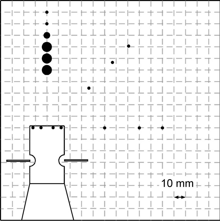 (b)
(b)
Figure 12. Ranges of drawing chemical samples for the systems waving the maxilliped arms (a) vertically and (b) horizontally.
were almost zero for those chemical source locations. Therefore, the crayfish robot shown in Figure 3 was fabricated after the prototype system waving the maxilliped arms vertically.
4. Comparison between Maxilliped Arms and Pump
The robot head equipped with a suction opening was compared with the prototype sensing system waving the maxilliped arms vertically. The chemical source was placed in sequence at the front and at three points obliquely forward from the robot head. In this set of experiments, the robot head was suspended in the Plexiglas water tank. The time required to draw a chemical substance from 40 mm ahead of the robot, (x, y) = (40 mm, 0 mm), using the maxilliped arms was approximately 15 s, which is comparable to real crayfish [4]. For the robot head with the suction opening, the flow rate of the pump was adjusted to equalize the time required to draw a chemical from (x, y) = (40 mm, 0 mm) to 15 s.
Table 1 shows the summary of the results. The sensor responses and the visualized movement of the released chemical showed that the chemical was drawn to the sensing electrodes in 20 s at the latest after the start of the flow generation, even if the source was placed at the farthest point of the four source locations. As described in the previous section, the reception rate was defined as the ratio of the time over which at least one of the four sensor response values exceeded the predefined threshold, 1.2 μA, in the 20 s time period after the sensors first started to respond. The values were obtained by averaging over three repeated measurements.
Figure 13 shows the typical sensor response curves for the chemical source placed at (x, y) = (20 mm, 40 mm). When the maxilliped arms were used, water sam-
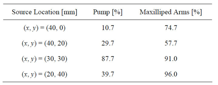
Table 1. Reception rates of chemical substance at the sensors.
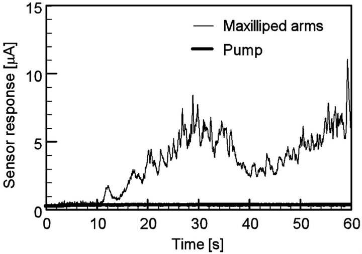
Figure 13. Response curves of sensor 2 when the source was placed at the left front of the robot, (x, y) = (20 mm, 40 mm). Sensor 2 showed the largest response of the four.
ples were drawn from almost all directions on the front side. As described in the previous section, the patch of the chemical substance was drawn to specific sensors depending on the direction of the source. When the pump was used, a smooth laminar flow field was created. Owing to the strong shear in the flow field, the chemical patch drawn to the pump had a thin filamentous structure, as shown in Figure 2(b). The thin streak of the chemical substance often passed between the sensing electrodes as shown in Figure 14, and no signal was obtained from the sensors in such cases. Therefore, the robot equipped with a pump has many blind spots. Since the generated flow field slightly fluctuates over time, the drawn chemical sometimes hit one of the sensing electrodes. In such cases, a large response was observed for a short time, as shown in Figure 15. Therefore, the variations in the reception rates for the triplicate measurements were large for the suction by the pump although the averaged reception rate was low. For the source location, (x, y) = (20 mm, 40 mm), the reception rates calculated from the first, second, and third experiments were 19%, 0%, and 100%, respectively.
In contrast, the maxilliped arms introduce some disturbances into the flow field. A thin filamentous chemical patch was mixed with the surrounding water, and its size grew when it approached the maxilliped arms. As shown in Figure 16, a diluted but wider streak of the chemical substance was formed from the source. The probability for the patch to hit the sensors was therefore significantly increased as shown in Table 1 (see also Figgures 13 and 15). The observed sensor responses showed some fluctuations owing to the disturbances in the flow. However, high reception rate was constantly obtained. For the source location, (x, y) = (20 mm, 40 mm), the reception rates calculated from the first, second, and third experiments were 100%, 100%, and 88%, respectively. Although the disturbances introduced into the flow field deteriorate the direction determination capability of the robot to some extent, the deterioration was not too large to mess up the direction determination entirely.
5. Chemical Source Localization
Chemical source localization trials were conducted in the water pool. Similarly to the prototype sensing system that waves the maxilliped arms vertically, the crayfish robot is able to draw and detect the chemical substance from a wide angular range. As described in section 2.1, the robot was programmed to perform the predefined behavior patterns when the response of at least one sensor exceeded the threshold value. Owing to the increased noise level in the potentiostat circuit of the robot, the threshold value was changed to 2.5 mA. The chemical source was placed in sequence at (x, y) = (40 mm, 0 mm), (30 mm, 30 mm) and (30 mm, −30 mm). Chemical source localization trials were repeated 5 times for each source location. When the robot approached the chemical source and the sensor protection ring mounted in front of the sensing electrodes hit the stainless-steel tube releasing the ascorbic acid solution, the trial was regarded as success. If the robot was not able to reach the source within 180 s, that trial was regarded as failed.
Figure 17 shows an example of the trajectory of the
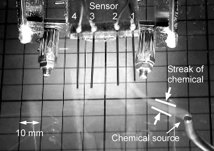
Figure 14. Visualized image of the chemical drawn by the pump.
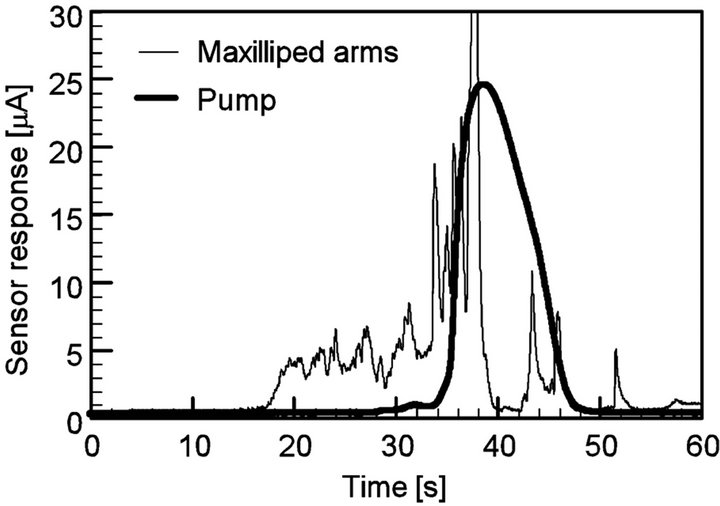
Figure 15. Response curves of sensor 2 when the source was placed at the left front of the robot, (x, y) = (30 mm, 30 mm). The chemical drawn by the pump hit sensor 2 from 34 s to 46 s.
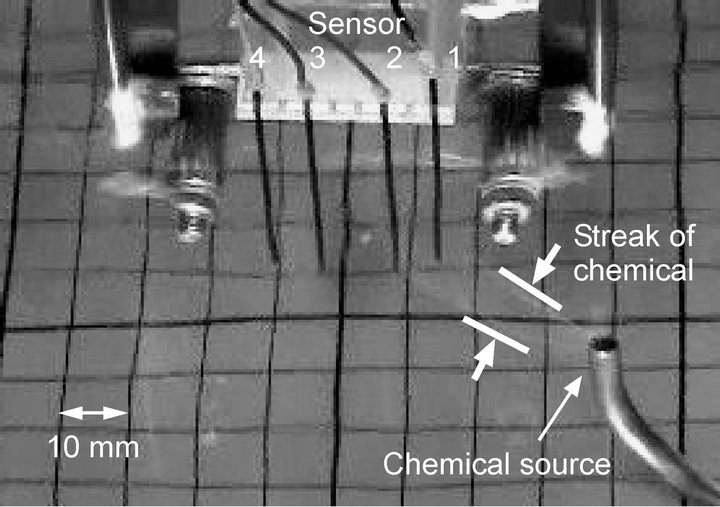
Figure 16. Visualized image of the chemical drawn by water currents generated by waving maxilliped arms.
robot approaching the chemical source in a successful trial. The thick arrows represent the trajectory of the center of the four sensors. At the beginning of each trial, no signal was obtained from the sensors. When waving of the maxilliped arms was initiated, the water currents generated by the arms brought the chemical substance from the source. Then, the robot detected the chemical, and moved in the direction of the sensor with the highest response. The robot succeeded in approaching the chemical source by repeating the acquisition of the sensor responses and the locomotion in the appropriate directions. As seen from the trajectory shown in Figure 17, the robot sometimes oriented in wrong directions while approaching the source. However, the robot turned back again toward the source in the following steps. In such cases, the water currents generated by the maxilliped arms helped in regaining signals by drawing chemical patches from the source.
Among the fifteen trials conducted, the robot failed in the chemical source localization only once when the source was placed at (x, y) = (30 mm, 30 mm). The high success rate suggests the effectiveness of active flow generation. In the failed trial, the robot made a wrong turn at the very beginning of the trial as shown in Figure 18. After this wrong turn, the relative location of the chemical source with respect to the robot came to be on the rear side of the robot. Afterward, the robot was not able to perform the direction determination properly. The robot can draw a chemical even from the rear side. However, the intensive motion of the maxilliped arms scatters the chemical before it reaches the sensors. The scattered chemical sometimes reached the sensing electrodes on the side opposite to the chemical source. Future work should be addressed to the optimization of the way of mounting the maxilliped arms as well as the structure of the maxilliped arms and the shape of the robot head to accomplish better chemical reception from all directions.
6. Scanning of Field
In the experiments described in the previous section, the robot stayed at the start point until the chemical substance was drawn from the source and the sensors started to respond. A nearby chemical source can be localized in this way. However, there is a limit in the distance over which the chemical can be drawn. A crayfish generally walks around in his/her territory while waving the maxillipeds to search for food. In most applications, the underwater robot needs to search a large field for a chemical source. Therefore, the robot must first scan the given field to spot the area where a chemical substance exists. Scanning can be done by random walk or by systematic sweeping. In either case, the flow field generated by the maxilliped arms enables efficient search. The robot can detect the chemical even if the source is placed off the scanning trajectory, and therefore, the density of the random walk or the sweeping motion can be reduced.
Experiments were conducted to show the effect of the active flow generation. The responses of the sensors on the robot were recorded while moving the robot slowly along a straight path. The chemical source was placed
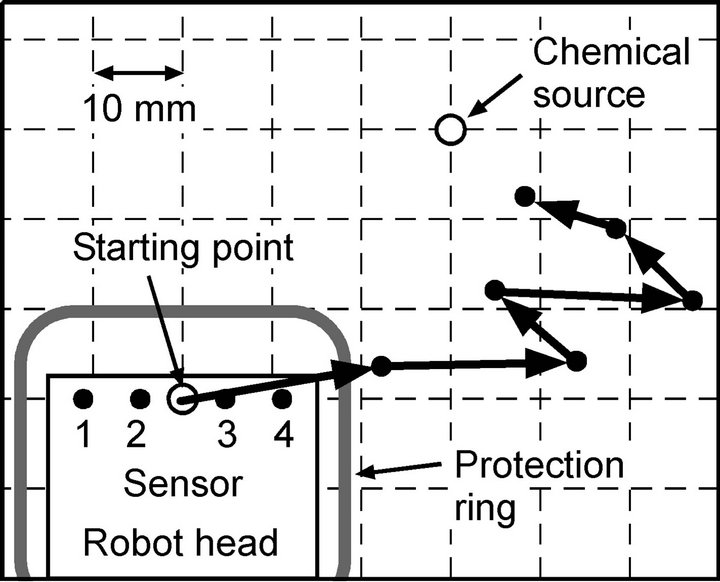
Figure 17. Trajectory of the robot successfully approaching the chemical source. Since the protection ring protrudes from the robot head by 10 mm to the front, the trajectory stops approximately 10 mm short of the source.
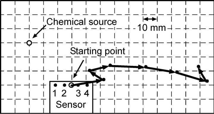
Figure 18. Trajectory of the robot in the failed trial.
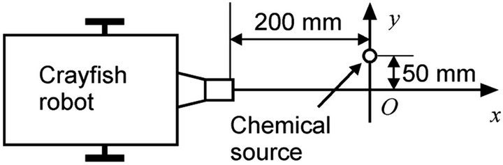
Figure 19. Setup of the scanning experiment. The robot was made to pass by the chemical source.
200 mm front and 50 mm left from the robot, as shown in Figure 19. The robot was programmed to repeat a 5 s pause and a forward movement by 20 mm at a speed of 10 mm/s. Figure 20(a) shows the sensor response curves recorded while the robot was moving along the path with waving of the maxilliped arms. Almost no sensor responses were obtained at first, but the sensor response values began to increase at x = –20 mm. The larger response of sensor 1 clearly indicates the existence of a nearby chemical source on the left side of the robot. The trial was repeated three times and similar sensor response curves were obtained in all trials.
Figure 20(b) shows the sensor response curves recorded without waving the maxilliped arms. In two out of three trials, the sensors showed no response at all as shown in Figure 20(b). Therefore, the robot would often pass by the chemical source without noticing its presence even though the source is placed only a few centimeters away from the trajectory of the robot. In one trial without waving the maxilliped arms, the sensors showed large responses as shown in Figure 20(c). From the observation of the motion of the visualized chemical solution, it was found that slight convective flow was sometimes generated in the water pool owing to the small temperature variations. When the sensor response curves shown in Figure 20(c) were recorded, the plume of the chemical was extending to the negative y-axis direction across the trajectory of the robot. Therefore, the chemical was detected on the robot trajectory without actively drawing the chemical from the source. In the absence of the convective flow, the released chemical stayed in the vicinity of the source or was pushed away from the robot due to the water currents caused by the locomotion of the robot itself.
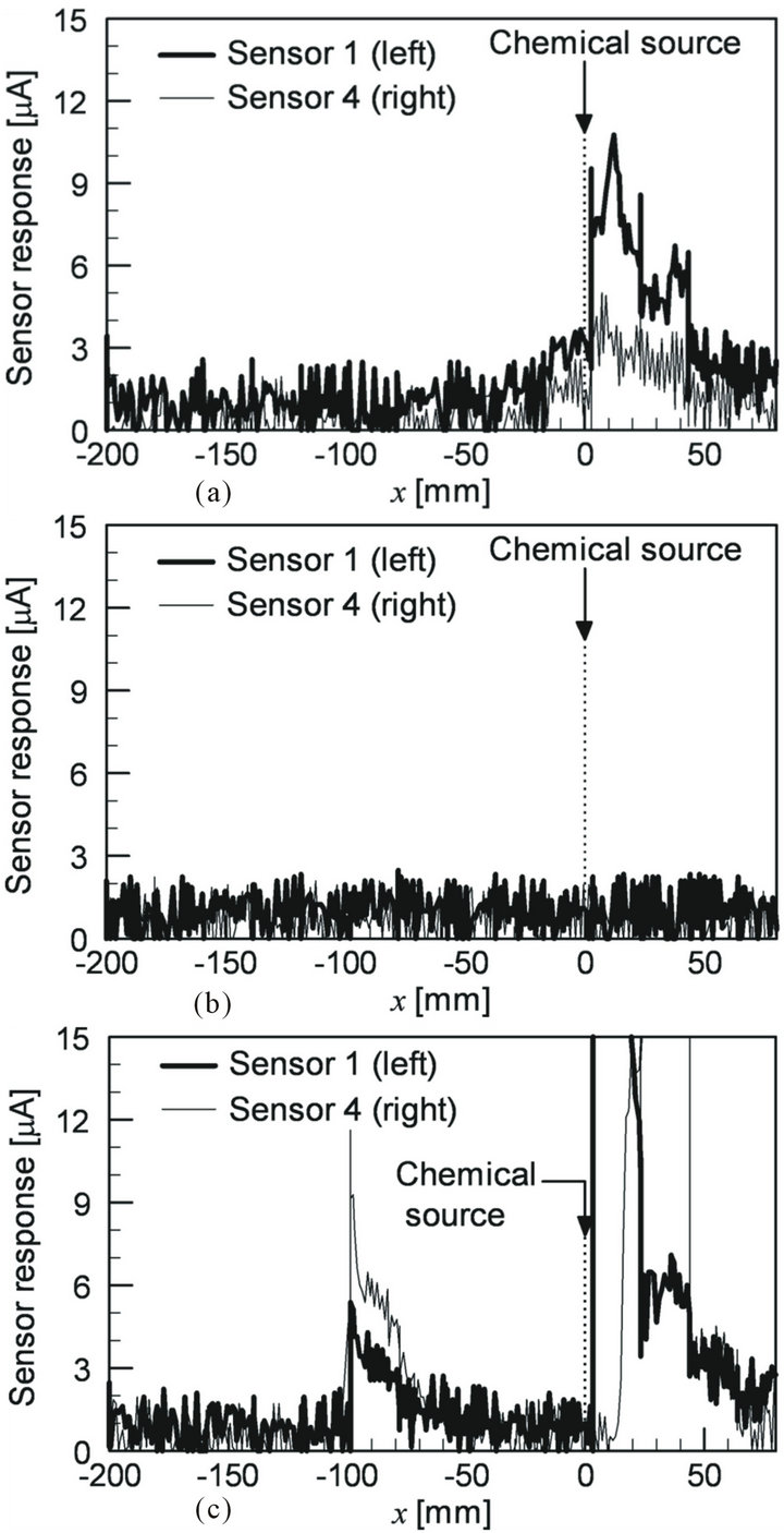
Figure 20. Sensor responses recorded while the robot was passing by the chemical source (a) with and (b) without waving the maxilliped arms. In the trial shown in (c), the maxilliped arms were not waved, but the chemical was detected with the help of convective flow.
The existence of the convective flow was also observed in the experiments in which the arms were waved. When the sensor responses shown in Figure 20(a) were recorded, the released chemical was drifted by the convective flow at a rate of 6 mm/s in the direction away from the trajectory of the robot. However, the water currents generated by the maxilliped arms overcame the convective flow as well as the water currents caused by the locomotion of the robot. The robot thus succeeded in detecting the existence of the chemical source. These experimental results suggest that the efficiency for scanning a large field can be improved by waving the maxilliped arms.
7. Conclusion
The autonomous wheeled underwater robot was developed for chemical source localization. The robot has two arms that mimic the maxillipeds of a crayfish. Water currents generated by waving them bring the chemical substance toward the sensors. When the arms were waved vertically, a three-dimensional flow field was generated and the chemical was drawn from a wide horizontal angular range. In contrast, the flow field generated by waving the arms horizontally brought the chemical to the sensors only from a narrow frontal region. Better chemical reception was attained by the water currents generated with the maxilliped arms than those generated by a pump. The direction of a chemical source can be determined simply by comparing the responses of the four electrochemical sensors. The robot was able to localize a chemical source with a high success rate. Actively generated flow also helps in detecting a nearby chemical source while scanning the area. The proposed robotic system can be used as a prototype to develop a larger robot for larger area coverage. It can be also used as a tool for in-depth biological study on the behavioral mechanisms of crayfish.
8. Acknowledgements
The authors would like to thank Thomas Breithaupt with the Department of Biological Sciences in the University of Hull for insightful discussions and suggestions.
REFERENCES
- E. A. Arbas, M. A. Willis and R. Kanzaki, “Organization of Goal-Oriented Locomotion: Pheromone-Modulated Flight Behavior of Moths,” In: R. D. Beer, R. E. Ritzmann and T. McKenna, Eds., Biological Neural Networks in Invertebrate Neuroethology and Robotics, Academic Press, San Diego, 1993, pp. 159-198.
- P. A. Moore and J. L. Grills, “Chemical Orientation to Food by the Crayfish Orconectes rusticus: Influence of Hydrodynamics,” Animal Behaviour, Vol. 58, No. 5, 1999, pp. 953-963. doi:10.1006/anbe.1999.1230
- F. W. Grasso and J. A. Basil, “How Lobsters, Crayfishes, and Crabs Locate Sources of Odor: Current Perspectives and Future Directions,” Current Opinion in Neurobiology, Vol. 12, No. 6, 2002, pp. 721-727. doi:10.1016/S0959-4388(02)00388-4
- T. Breithaupt, “Fan Organs of Crayfish Enhance Chemical Information Flow,” Biological Bulletin, Vol. 200, No. 2, 2001, pp. 150-154. doi:10.2307/1543308
- P. G. Brewer, K. C. Hester and N. Nakayama, “Chemical Weapons on the Sea Floor: A Plea for Complete Information,” Proceedings of Oceans 2008—MTS/IEEE Kobe Techno-Ocean, Kobe, 8-11 April 2008, pp. 1-5.
- P. Courmontagne, “A New Approach for Mine Detection in SAS Imagery,” Proceedings of Oceans 2008—MTS/ IEEE Kobe Techno-Ocean, Kobe, 8-11 April 2008, pp. 1- 8.
- J. Yoo, S. Tabeta, T. Sato and S. Jeong, “Risk Assessment for the Benzene Leakage from a Sunken Ship,” Proceedings of Oceans 2008—MTS/IEEE Kobe TechnoOcean, Kobe, 8-11 April 2008, pp. 1-7.
- M. J. Weissburg, D. B. Dusenbery, H. Ishida, J. Janata, T. Keller, P. J. W. Roberts and D. R. Webster, “A Multidisciplinary Study of Spatial and Temporal Scales Containing Information in Turbulent Chemical Plume Tracking,” Environmental Fluid Mechanics, Vol. 2, No. 1-2, 2002, pp. 65-94. doi:10.1023/A:1016223500111
- G. S. Settles, “Sniffers: Fluid-Dynamic Sampling for Olfactory Trace Detection in Nature and Homeland Security,” Journal of Fluids Engineering, Vol. 127, No. 2, 2005, pp. 189-218. doi:10.1115/1.1891146
- P. Denissenko, S. Lukaschuk and T. Breithaupt, “The Flow Generated by an Active Olfactory System of the Red Swamp Crayfish,” Journal of Experimental Biology, Vol. 210, No. 23, 2007, pp. 4083-4091. doi:10.1242/jeb.008664
- F. W. Grasso and J. Atema, “Integration of Flow and Chemical Sensing for Guidance of Autonomous Marine Robots in Turbulent Flows,” Environmental Fluid Mechanics, Vol. 2, No. 1-2, 2002, pp. 95-114. doi:10.1023/A:1016275516949
- W. Li, J. A. Farrell, S. Pang and R. M. Arrieta, “MothInspired Chemical Plume Tracing on an Autonomous Underwater Vehicle,” IEEE Transactions on Robotics, Vol. 22, No. 2, 2006, pp. 292-307. doi:10.1109/TRO.2006.870627
- H. Ishida, H. Sakata, T. Moriizumi and T. Breithaupt, “Underwater Odor Compass to Locate a Chemical Source,” Technical Digest of the 10th International Meeting on Chemical Sensors, Tsukuba, 11-14 July 2004, pp. 104- 105.
- T. Kikas, H. Ishida and J. Janata, “Chemical Plume Tracking 3. Ascorbic Acid: A Biologically Relevant Marker,” Analytical Chemistry, Vol. 74, No. 15, 2002, pp. 3605- 3610. doi:10.1021/ac0202076
NOTES
*Corresponding author.