Journal of Transportation Technologies
Vol.04 No.04(2014), Article ID:51025,5 pages
10.4236/jtts.2014.44030
Simulation Analysis of Car Front Collision Based on LS-DYNA and Hyper Works
Chunke Liu, Xinping Song*, Jiao Wang
College of Automotive Engineering, Shanghai University of Engineering Science, Shanghai, China
Email: lck6200@163.com, *wxty777@163.com
Copyright © 2014 by authors and Scientific Research Publishing Inc.
This work is licensed under the Creative Commons Attribution International License (CC BY).
http://creativecommons.org/licenses/by/4.0/


Received 21 July 2014; revised 15 August 2014; accepted 8 September 2014
ABSTRACT
Based on the basic principle of vehicle crash analysis using the finite element method, a car finite element model was built by using Hypermesh software. To simulate the front collision test of the car, the LS-DYNA software is adopted to calculate the deformation of the car and the acceleration time history curves during the crashing process; the anti-impact capability of the car is evaluated from this simulation. The results demonstrate that the improvement of local structure can promote the crashworthiness of the car, but the further improvement needs a major change of the car structure.
Keywords:
Frontal Collision, Simulation Analysis, LS-DYNA, Hyper Works

1. Introduction
The statistics of national road traffic situation have confirmed 1,840,998 cases of road traffic accident in China in the first half of 2011. Among them, the road accidents involved 91,811 casualties; 25,864 people were dead; 106,370 people were injured and direct property loss was 440 million Yuan [1] .
With the development of economy, more and more families have bought private cars. However, the high mortality rate of traffic accidents lets people increasingly value the car passive safety. For over 30 years, many countries have carried out the NCAP (New Car Assessment Program) in the world [2] . China Automotive Technology Center formally established the C-NCAP (China New Car Assessment Program) in conjunction with standard, the technical level of China’s automotive and economic development in 2006. Then, C-NCAP Management Center designed to update the “C-NCAP Management Regulations (2012 Edition)” in accordance with international NCAP trends. In this paper, the car frontal crash simulation model is calculated according to the latest C- NCAP. The car structure was improved [3] .
2. Establishment Model and Calculation
2.1. Importing Vehicle Model and Meshing
First, car body model is established by using CATIA software and then using the software Hyper Mesh reads it and converts into hm format, at the same time goes geometry repair and meshing by the software Hyper Mesh [4] .
2.2. Materials and Property Settings
The right material properties for the simulation result have important influence in the vehicle collision experiment. The vast majority of material data are obtained through experiments in the vehicle finite element model [5] . The main part of car is composed of sheet metal parts, so elastic-plastic mechanics characteristics material MAT340 is adopted.
Another type of collision components is almost not deformable, such as engine, transmission etc. They can be chosen MAT20 material model [6] . SDMAT1 material model can be used to simulate elastic damping. MAT_ SOPTWELD material model can be used to simulate solder material.
2.3. Connection Settings
In the process of collision force transfer is through the connection between parts and the parts [7] . In the finite element model the common connection ways mainly have the following: The connection between the sheet metal parts are spot welding connections in body parts; In the model, the bolt connection mainly adopts rigid connection unit, rigid panel function is used to make the two bolt holes coupled together; In order to keep the body outer surface smooth and complete, the connection between the parts and the outer plates uses glue and edging treatment; Part of the chassis, a lot of parts are moving contact, there are several common connections: Ball connection, universal joint connection etc.
2.4. Parameter Settings
In order to prevent the penetration phenomenon, overall vehicle finite element model is defined as a general- sided contact [8] . Reference “C-NCAP Management Rules (2012 Edition)” the initial velocity is set to 50 km/h. Gravity is set to 9.8 m/s2. Car collision time is set 120 ms. Finite element model is shown in Figure 1.
3. Simulation Results and Analysis
3.1. Simulation Reliability Analysis
From Figure 2, the total energy line keeping level indicates that energy is conserved in the process of collision. Hourglass energy with the ratio of the total energy is 1.46% less than 3% of the value of industry regulations. The increasing quality with the ratio of the initial vehicle quality ratio is 3.46% less than 5% of the value of industry regulations. Therefore, the credibility of the entire simulation meets the requirement. The smooth transition curves meet simulation requirement.

Figure 1. Car finite element model.
3.2. Vehicle Deformation Analysis
In Hyper View post-processing software, vehicle deformation can be seen at the different time after d3plot file importing. Car collision deformation in the end is shown in the Figure 3.
The front energy absorption components of the car deforming sufficiently can be seen from the Figure 3. Hood is completely bent, tire contacts with fender, bumper and the front longitudinal beam deformation fully. The above phenomenon can guarantee energy absorption in the process of the collision.
On both sides of the door and a column don’t have obvious deformation that can help the crew to open the door to escape. The tank doesn’t have large deformation that can prevent the car getting fire. The floor and the exhaust pipe are slightly bent down. The back of the car body has obviously risen.
3.3. The Front Longitudinal Beam Deformation and Dash Panel Intrusion Analysis
The front longitudinal beam is the main kinetic energy absorber during crash simulation of the vehicle. The ideal front longitudinal beam deformation is that the front of the deformation sufficient and the rear of the deformation slight, so that the car can efficiently absorb the kinetic energy, avoid high acceleration and prevent dash panel invading largely. It can provide safe space for driver and front passenger. Figure 4 shows front longitudinal beam collision deformation during different times.
As can been seen from Figure 4 that the front longitudinal beam deform from the front to the rear with the passage of the time. The front of the front longitudinal beam first happening completely crushing is helpful for

Figure 2. Change of energy during the crash.

 (a) (b)
 (c) (d)
Figure 3. Car collision deformation in the end: (a) 45˚ angle perspective diagram; (b) Front view; (c) Top view; (d) Bottom view.

 (a) (b)
 (c) (d)
Figure 4. Front longitudinal beam collision deformation during different times: (a) Initial shape; (b) Time of 30 ms; (c) Time of 80 ms; (d) Time of 120 ms.
the absorption of energy. Over time the center and rear the front longitudinal beam appearing different degree of bending is harmful to the dash panel intrusion.
The dash panel displacement contours can show the direct invasion of the amount of the dash panel to the cab. The amount of the invasion is related to living space in the collision process, so the smaller amount of the invasion is beneficial to provide enough space for the front passenger. Figure 5 is the dash panel displacement contours relative to the cab. From the picture we can know that the amount of the invasion in the middle of the dash panel is 38.1 cm that has greatly threatened the survival of the front passenger.
3.4. Acceleration Analysis
The body after B-pillar deformation basic does not occur and B-pillar acceleration deceleration can be a good representative of the true passenger feel in the process of collision. So B-pillar acceleration deceleration is usually used as an evaluation index of the vehicle acceleration response. The acceleration curves of the right and left B pillar during collision shown in Figure 6. The car collision lasts up to 87 ms, the right B pillar maximum acceleration is 36.3 g at the time of 54.8 ms, and the left B pillar maximum acceleration is 40.1 g at the time of 71.1 ms.
4. The Improvement Analysis and Suggestions
4.1. Comparative Analysis Before and After Improvements
The main energy-absorbing structure is front longitudinal beam in the collision. The deformation of front longitudinal beams is mainly to the mixture of crushing and bending mode. Figure 7(a) is the picture of the front lon- gitudinal beams deformation before improvements. The picture shown that collision deformation is serious, total energy absorbed 31,520 J, 19.7% of the total energy.
During the collision, the front of the front longitudinal beams crush deformation and the rear of it bending deformation occurs, so that energy absorption efficiency is low. In order to prevent bending deformation, the thickness of the front longitudinal beam increase from 1.8 mm to 2.5 mm. Figure 7 shows that bending deformation is weaken and crush deformation is enhanced after improvement. Meanwhile, the energy absorption increased to 37,920 J, accounting for 23.7% of the total energy, there has been a significant improvement. In reducing the front longitudinal beams bending deformation and enhancing crushing deformation, at the same time, in order to effectively reduce the dash panel invasion and increase the front passenger living space the thickness

Figure 5. Relative displacement contours of dash panel.
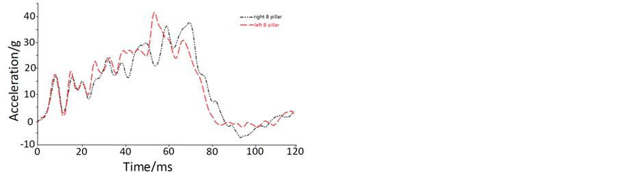
Figure 6. Acceleration curve of B-pillar during collsion.

 (a) (b)
Figure 7. Deformation of front longitudinal beams between before and after improvement. (a) Before improvement; (b) After improvement.
of the dash panel increases from 1.0 mm to 1.5 mm. As shown in Figure 8, the amount of the dash panel invasion deduces from 38.1 cm to 27.2 cm, increasing the front passenger living space.
Although the local collision performance improved, but not the car collision don’t completely improve. As shown in Figure 9, A-pillar has a slight deformation at the end of collision. It impedes opening the front door for escaping, while the amount of the dash panel invasion is still too larger.
4.2. Suggestions for Improvement
1) Absorbing box structure can be added at the back of the bumper, so that the absorption performance can be further improved. It can reduce the amount of the dash panel invasion.
2) The strength of reinforcing ribs which inside the front door is increased, which the strength of the A-pillar is increased, so that the chance of escaping is increased.
5. Conclusion
The simulation result shows that the front longitudinal beams don’t have enough strength to prevent bending deformation. Energy absorption is inadequate, while the excessive invasion of the dash panel easily hurts front

Figure 8. Relative displacement contours after improved thick- ness of dash panel.

Figure 9. Deformation of car after improvement.
passengers. The dash panel invasion and the front longitudinal beam deformation have been effectively improved by changing their thickness. However, the local improvement can’t comprehensively improve the performance of the car collision. The amount of dash panel invasion needs to be further reduced, which is more conducive to the safety of front passengers.
References
- Guillow, S.R., Lu, G., Grzebieta, R.H. Malik, A.S. and Boyko, O. (2001) Quasi-Static Axial Compression of Thin- Walled Circular Aluminum Tubes. International Journal of Mechanical Science, 435, 2103-2123. http://dx.doi.org/10.1016/S0020-7403(01)00031-5
- Zarei, H.R. and Kroeger, M. (2006) Multiobjective Crashworthiness Optimization of Circular Aluminum Tubes. Thin- Walled Structures, 44, 301-308. http://dx.doi.org/10.1016/j.tws.2006.03.010
- Santosa, S. and Wierzbicki, T. (1998) Crash Behavior of Box Columns Filled with Aluminum Honeycomb or Foam. Computers & Structures, 68, 343-367. http://dx.doi.org/10.1016/S0045-7949(98)00067-4
- Ghamarian, A., Zarei, H.R. and Abadi, M.T. (2011) Experimental and Numerical Crashworthiness Investigation of Empty and Foam-Filled End-Capped Conical Tubes. Thin-Walled Structures, 49, 1312-1319. http://dx.doi.org/10.1016/j.tws.2011.03.005
- Evin, E. and Tomáš, M. (2012) Comparison of Deformation Properties of Steel Sheets for Car Body Parts. Procedia Engineering, 48, 115-122.
- Zhou, Y.J. (2011) Crashworthiness Research on S-Shaped Front Rails Made of Steel-Aluminum Hybrid Materials. Thin-Walled Structures, 49, 291-297. http://dx.doi.org/10.1016/j.tws.2010.10.007
- Zhang, Y., Sun, G.Y. and Li, G.Y. (2012) Optimization of Foam-Filled Bitubal Structures for Crashworthiness Criterial. Materials & Design, 38, 99-109. http://dx.doi.org/10.1016/j.matdes.2012.01.028
- Zarei, H.R. and Kroger, M. (2008) Bending Behavior of Empty and Foam-Filled Beams: Structural Optimization. International Journal of Impact Engineering, 35, 521-529. http://dx.doi.org/10.1016/j.ijimpeng.2007.05.003
NOTES

*Corresponding author.