Journal of Signal and Information Processing
Vol. 4 No. 2 (2013) , Article ID: 30991 , 7 pages DOI:10.4236/jsip.2013.42015
A Fuzzy Controller for Blood Glucose-Insulin System
![]()
1The College of Industrial Technology, Misurata, Libya; 2Misurata University, Misurata, Libya.
Email: ahmed_bensasi@yahoo.co.uk, elmalki_m@yahoo.com
Copyright © 2013 Ahmed Y. Ben Sasi, Mahmud A. Elmalki. This is an open access article distributed under the Creative Commons Attribution License, which permits unrestricted use, distribution, and reproduction in any medium, provided the original work is properly cited.
Received December 28th, 2012; revised January 25th, 2013; accepted February 4th, 2013
Keywords: Diabetes; Blood Glucose; Closed-Loop; Continuous Insulin Infusion; PID Controller; Fuzzy Logic Controller
ABSTRACT
Diabetes therapy is normally based on discrete insulin infusion that uses long-time interval measurements. Nevertheless, in this paper, a continuous drug infusion closed-loop control system was proposed to avoid the traditional discrete approaches by automating diabetes therapy. Based on a continuous insulin injection model, two controllers were designed to deal with this plant. The controllers designed in this paper are: proportional integral derivative (PID), and fuzzy logic controllers (FLC). Simulation results have illustrated that the fuzzy logic controller outperformed the PID controller. These results were based on serious disturbances to glucose, such as exercise, delay or noise in glucose sensor and nutrition mixed meal absorption at meal time.
1. Introduction
Many researchers have attempted to find methods for diagnosing and treating diabetes disease. One of the approaches is to design an automated closed-loop insulin delivery system. A fully automated closed-loop insulin delivery system (also known as an artificial pancreas) could potentially be the ultimate answer for blood glucose (BG) control in diabetic patients. This system can mimic the activity of a normal pancreas and is capable of maintaining physiological BG levels for insulin-dependent diabetic patients.
Such an artificial pancreas system can theoretically produce tight glucose control without finger-stick BG measurements, subcutaneous insulin injections, or hypoglycemic/hyperglycemic events, thereby, dramatically improves the quality of life for an insulin-dependent diabetic patient. The artificial pancreas is a system of integrated devices containing only synthetic materials, which substitutes for a pancreas by sensing plasma glucose concentration, calculating the amount of insulin needed, and then delivering the correct amount of insulin. Typically, such a device is comprised of a glucose monitoring sensor, an insulin pump, and a control algorithm to regulate the pump to deliver the insulin in order to maintain normoglycemia in presence of sensor measurements.
Figure 1 shows a basic block diagram of this type of

Figure 1. Block diagram of closed-loop insulin delivery system.
closed-loop control for the regulation of glucose levels. In this figure, a controller receives the difference between the glucose set point (desired BG) and the glucose reading, and uses this information to continuously adjust the rate of insulin delivery. The insulin infusion and glucose measurements are either invasive or non-invasive, however, usually achieve using the subcutaneous route [1,2]. This closed-loop control is very similar to the function that is performed by a healthy human pancreas; in other words, the research’s aim is to design a device that essentially functions as an artificial pancreas. This paper emphasises the need of a good quality controller when it comes to critical diabetes situations.
2. The Mathematical Model of Diabetes
In order to have a reliable automatic insulin delivery system operating under various physiological conditionsa model must be synthesized that has glucose-predicting ability and includes all the major energy-providing substrates at rest, as well as during physical activity. The mathematical models of metabolism proposed, in this paper, are glucose-based and have the contribution of free fatty acid (FFA) metabolism, which is an important source of energy for the body. Also, significant interactions exist among FFA, glucose, and insulin. It is important to consider these metabolic interactions in order to characterize the endogenous energy production of a healthy or a diabetic patient. Furthermore, physiological exercises are taken into account to induce the fundamental metabolic changes in the body. Figure 2 shows the simulation of a composite model which is capable of predicting FFA-glucose-insulin dynamics during rest and exercise [3].
A mixed meal model was employed to capture the absorption of carbohydrates (CHO), proteins, and FFA from
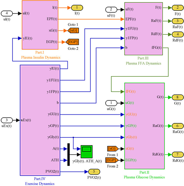
Figure 2. Composite model simulation of diabetic patient.
the gut into the circulatory system [4]. An exercise model was used to incorporate the effects of exercise on glucose and insulin dynamics to capture the changes in glucose and insulin dynamics during and after mild-to-moderate exercise. The mixed meal, and exercise models served as a disturbance to the proposed model. The overall diabetic plant comprises of 34 differential algebraic equations, which describe 20 states. The diabetic plant includes the composite model, and its disturbances (mixed meal, and exercise models). The model successfully captured the FFA-glucose interactions at the systemic level, and also effectively predicted mild-to-moderate exercise effects on glucose and FFA dynamics. Accordingly, this composite model was selected in this work to provide a platform for the development of closed-loop controllers to maintain glucose homeostasis of a diabetic patient.
3. Controllers Design and Simulation
Various types of control algorithms for blood glucose control have been reported in the literature. Some of these algorithms include: PID control [5,6], and fuzzy logic control [1,2].
However, our studies have focused on using the successfully captured FFA-glucose-insulin dynamics composite model presented in section two, which has never been used before for control purposes, to developing two control algorithms: the PID and the fuzzy logic controllers using Matlab/Simulink. The target blood glucose range that the controllers were supposed to attain and maintain is similar to healthy blood-glucose levels. The proposed blood-glucose range is between 70 mg/dl and 120 mg/dl before meals and less than 180 mg/dl after meals [5], and the maximum insulin infusion rate is constrained to 100 mU/min.
3.1. The PID Controller
The most traditional of all controllers is probably the proportional integral derivative (PID) controller. A PID controller uses a proportional term, an integral term, and a derivative term, each with a coefficient that provides a weight for that term. In many processes, especially industrial, PID controllers are used to keep some kind of a steady state. The controller takes a measurement from a plant process (diabetic mathematical model) and compares it with a set-point (reference) value of BG concentration. The difference (or “error” signal) is then used to adjust the input to the plant in order to bring the measured value back to its desired set-point. PID controller can adjust process outputs based on the history and rate of change of the error signal. The schematic diagram of the PID controller used with the composite model is shown in Figure 3.
3.2. The Fuzzy Logic Controller (FLC)
In the control theory field, fuzzy logic has emerged as a powerful tool to incorporate expert knowledge about systems into the controllers design. In particular, the ability of synthesizing expert knowledge in the fuzzy logic framework has raised a lot of attention in different engineering fields. In this research, a control algorithm was developed to incorporate “formalize” expert knowledge about the treatment of diabetes using fuzzy logic controller. This controller should be able to regulate the blood glucose (BG) level when the diabetic patient is subjected to a mixed meal disturbance or fluctuations in the measured glucose level due to error or noise in the measuring instrument.
Fuzzy logic control is furthermore an advanced process control, which imitates the logic of human thought

Figure 3. Simulation of the PID controller.
and much less rigid than calculations that computers generally perform. There are three steps for the process of a fuzzy logic algorithm: fuzzification, rules, and defuzzification. In this paper, it is assumed that there are two different inputs of fuzzy logic controller: the glucose concentration and the rate of change in glucose concentration, and one output of the dose of insulin.
The process of transforming inputs and output characteristics including the interval of variation for each variable and the fuzzy sets associated with the type of membership function (MF) is called fuzzification method. By the definition of the input fuzzy set, as shown in Figure 4, and the output fuzzy set as shown in Figure 5, a total of 17 IF-THEN rules were classified, as presented in Table 1. These rules were of AND (min) type antecedent. The output of the fuzzy concept is obtained, using defuzzification. The defuzzification strategy is based on the centroid of the area under the curve. Therefore, using the defuzzification process, the output gets an exact number (insulin dosage).
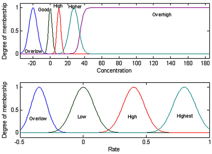
Figure 4. MF of the inputs of fuzzy logic controller.
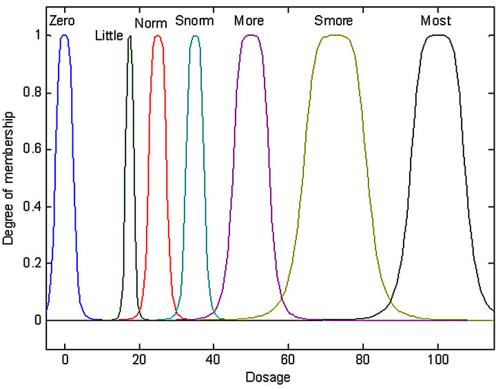
Figure 5. MF of the output of fuzzy logic controller.
4. Results of Controllers Tests
4.1. Single Mixed Meal Test
4.1.1. No Disturbance Test
In this type of test, we apply a single mixed meal and both controllers were examined to get the best response to this test. The following table, Table 2 shows the single mixed meal used in the simulation.
Figure 6 shows the response of the plant to the single mixed meal with no controllers. In other words, there is no insulin infusion.
Figure 7 shows the response of the plant to the single mixed meal when regulated by the PID method. Similarly, Figure 8 shows the response of the plant when controlled by the fuzzy logic controller. The measurement results obtained from this test are presented in Table 3.
4.1.2. Delay in Glucose Sensor Test
Here, both controllers were tested against time delay in the glucose sensor (i.e. five minutes delay). The single mixed meal used in the simulation is as shown in the first test Table 2.
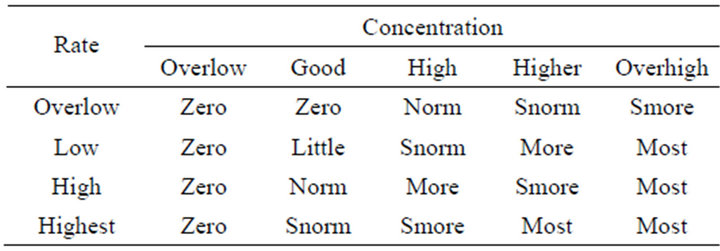
Table 1. Rules of fuzzy logic controller.
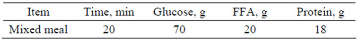
Table 2. Single mixed meal.
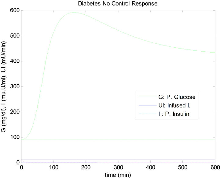
Figure 6. No control (no infused insulin) response of the plant to the single mixed meal.

Figure 7. PID controller response to single mixed meal.
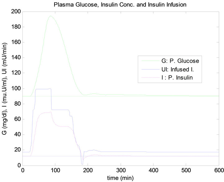
Figure 8. FLC controller response to single mixed meal.
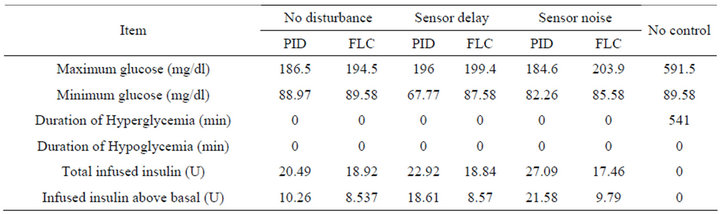
Table 3. Measurement results of controllers to different tests of single mixed meal.
The response of the plant to the single mixed meal with time delay when controlled by the PID algorithm is shown in Figure 9. Similarly, the response of the plant when controlled by the FLC is shown in Figure 10. The measurement results obtained from this test are presented in Table 3.
4.1.3. Noise in Glucose Sensor Test
In this type of test, we apply a single mixed meal as shown in the last section, with signal to noise ratio (SNR = 10 dB) in the glucose sensor. The simulation responses for both controllers are shown in Figures 11 and 12. The measurement results obtained from this test are presented in Table 3.
4.2. Daily Life Test
Here, we test how the controllers can deal with multi mixed meals and exercise, by supposing daily life of healthy people as shown in Table 4.
Figure 13 shows the response of the plant to the daily life test when controlled by the PID approach. Similarly, Figure 14 shows the response of the plant when regulated using the FLC.
Although, the mixed meal for lunch and the dinner
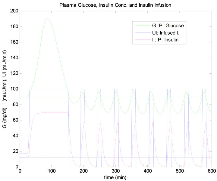
Figure 9. PID controller response to 5 min time delay.
has the same quantity, the blood glucose level has raised more after dinner than after lunch, thus infusing more insulin for both controllers, as shown in Figures 13 and 14. This result is due to the exercise that was done before the dinner time which caused the plasma FFA elevation, where increased availability of FFA at rest has an inhibi-
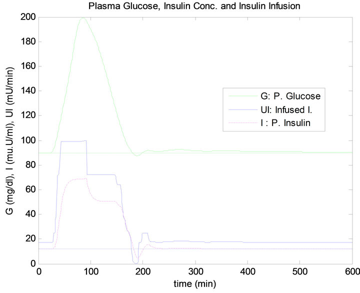
Figure 10. FLC controller response to 5 min time delay.
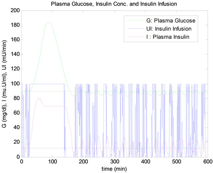
Figure 11. PID controller response to noise in G. sensor.
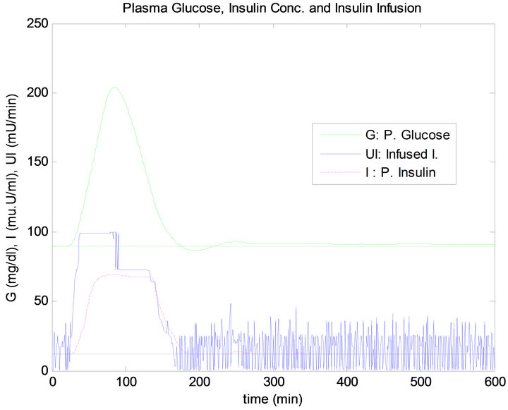
Figure 12. FLC controller response to noise in G. sensor.
tory effect on tissue glucose uptake, as shown in Figure 15. The measurement results obtained from daily life test are presented in Table 5.
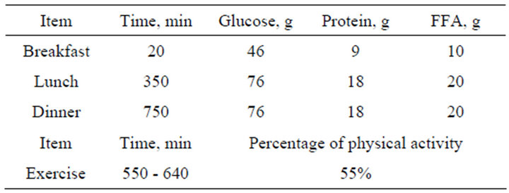
Table 4. Daily life of mixed meals and exercise.
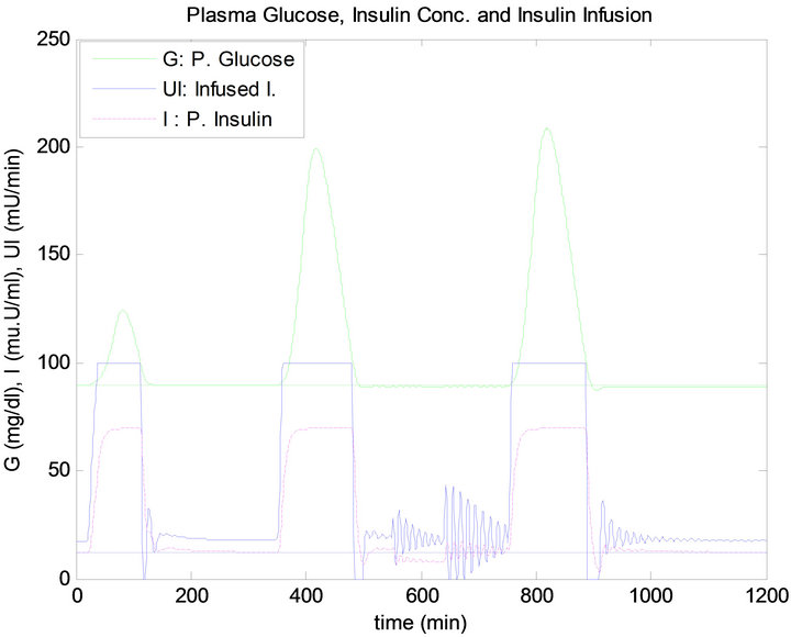
Figure 13. PID controller response to daily life.
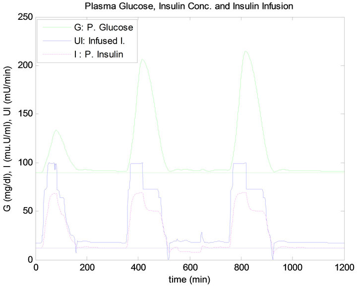
Figure 14. Fuzzy controller response to daily life.
5. Discussion and Conclusions
In the delay test of a single mixed meal, when the glucose sensor has 5 minutes time delay, the PID controller can not keep the blood glucose (BG) level at the basal level, producing a big drop in the BG level below the basal line. This results from the wrong insulin doses, which has a short term effect on his/her life causing danger to the patient. In contrast, the overshoot of BG concentration in the FLC is a little more than what happened in the PID
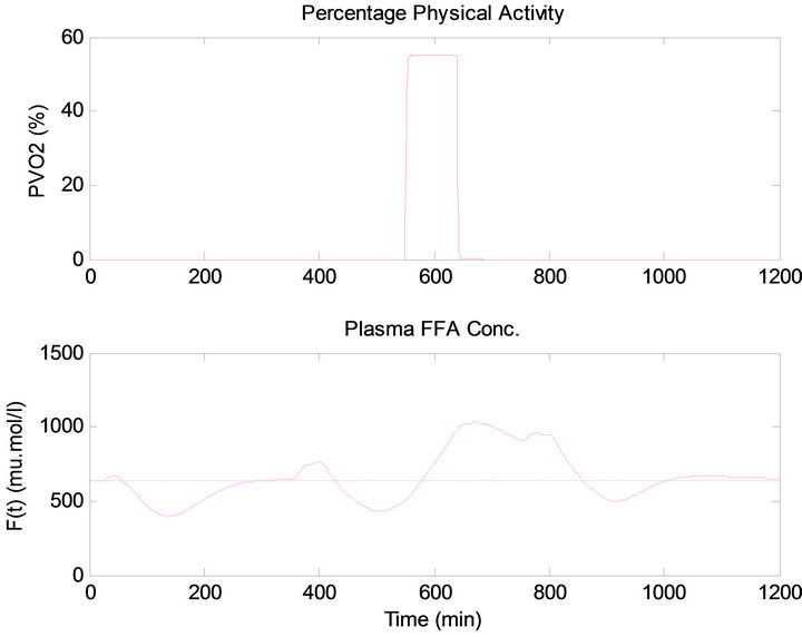
Figure 15. (Top) Percentage physical activity, (Bottom) plasma FFA concentration.
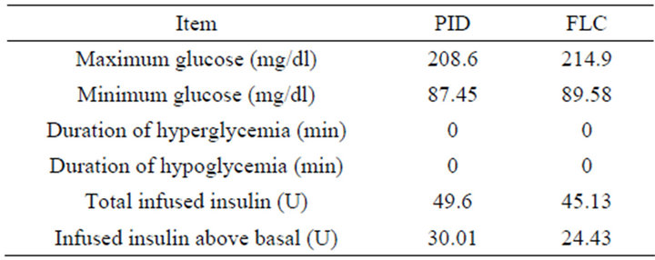
Table 5. Controllers measurement results of daily life test.
controller. Nevertheless, the FLC in the stage of steady state has a stable response with the basal level of the BG concentration, and the basal level of insulin infusion. Thus, the insulin infused by the FLC is less than the dosage infused by the PID controller as presented in Table 3. In comparison of the total insulin infusion in no disturbance test and sensor delay test, it is quite obvious that the 5 min time delay caused more insulin infusion in case of the PID controller, and made the most quantity of infused insulin above the basal level. In contrast, the FLC has infused almost similar quantities as shown in Table 3.
In the noise test, when the glucose sensor has a 10 dB SNR, this causes a big confusion in the response of the PID controller and this is shown clearly in the stage of steady state before and after the time of ingesting mixed meal. The response of the PID controller is not acceptable in the sense of control since the BG level has an oscillation causing a drop in BG level below the basal. In contrast, although the overshoot in the FLC is a little more than that what happen in the PID controller, the response of this controller in stage of steady state has kept the BG concentration almost at the basal level. The insulin infusion has a big fluctuation which will cause big extra effort on insulin pump. By comparing the total insulin infusion in no disturbance test and sensor noise test as presented in Table 3, it is very clear that noise has caused more insulin infusion in case of the PID controller compared to the FLC. Moreover, the PID has made the most infused quantity of insulin doses above the basal level.
The PID controller in daily life test has a proper response where soon after the overshoot that happened due to the ingestion of mixed meal, the BG level returned back to the basal level. However, the overshoot in the FLC is little more than that what happened in the PID controller, where the effect of long time of high overshoot has a long term effect on the life of the patient. In the stage of steady state, both controllers have the basal level of BG concentration, and basal level of insulin infusion. However, the PID controller has big oscillation of insulin infusion in the period of exercise time, which will cause extra effort on insulin pump. Also it is clear from Table 5 that insulin infused by the FLC is less than by the PID controller.
In conclusion, taking into account all previous tests with both controllers, there were no case of hyperglycemia (BG more than 270 mg/dl) or hypoglycemia (BG less than 60 mg/dl) as presented in Tables 3 and 5. However, resulting tables and figures have shown that the FLC is more reliable, safer and has less insulin consumption than the PID controller. Furthermore, real world cases should have a delay or/and noise in glucose sensor. Therefore, the FLC would be preferable and advisable when it comes to critical diabetes cases.
REFERENCES
- J. Chen, K. Cao, Y. Sun, Y. Xiao and X. Su, “Continuous Drug Infusion for Diabetes Therapy: A Closed-Loop Control System Design,” Eurasip Journal on Wireless Communications and Networking, Vol. 2008, No. 44, 2008, Article ID: 495185.
- L. Kardar, A. Fallah, S. Gharibzadeh and F. Moztarzadeh, “Application of Fuzzy Logic Controller for Intensive Insulin Therapy in Type 1 Diabetic Mellitus Patients by Subcutaneous Route,” Biomedical Engineering, Amirkabir University of Technology, WSEAS Transactions on Systems and Control, Vol. 3, No. 9, 2008, pp. 712-721.
- A. Roy, “Dynamic Modelling of Free Fatty Acid, Glucose, and Insulin during Rest and Exercise in Insulin Dependent Diabetes Mellitus Patients,” University of Pittsburgh, Pittsburgh, 2008.
- E. D. Lehman and T. Deutsch, “The Physiological Model of Glucose-Insulin Interaction in T1DM,” Journal of Biomedical Engineering, Vol. 14, No. 3, 1992, pp. 235-242. doi:10.1016/0141-5425(92)90058-S
- E. Berger, “Modeling Diabetes to Achieve Closed-Loop Control of Glucose Levels: A Literature Review,” Pennsylvania State University, 2007.
- E. Friis, “Modeling and Simulation of Glucose-Insulin Metabolism,” Technical University of Denmark, 2007.