Journal of Flow Control, Measurement & Visualization
Vol.06 No.02(2018), Article ID:83831,12 pages
10.4236/jfcmv.2018.62009
Development of Flexible Spherical Actuator with 3D Coordinate Measuring Device
Yasuko Matsui, Tetsuya Akagi, Shujiro Dohta, Wataru Kobayashi, Hiroaki Tamaki
Graduate School of Engineering, Okayama University of Science, Okayama, Japan

Copyright © 2018 by authors and Scientific Research Publishing Inc.
This work is licensed under the Creative Commons Attribution International License (CC BY 4.0).
http://creativecommons.org/licenses/by/4.0/


Received: December 8, 2017; Accepted: February 24, 2018; Published: April 18, 2018
ABSTRACT
Rehabilitation devices help to recover the physical abilities of patients. This study aims to develop a portable rehabilitation device that is safe to use when patients are holding it by hands. In a previous study, to realize a home rehabilitation device, a flexible spherical actuator that can provide motion to patients was developed. In this study, to measure the relative position between both handling stages, a 3D coordinate measuring device using three wire-type linear potentiometers and an embedded controller was proposed and tested. In this paper, the spherical actuator with built-in 3D coordinate measuring device is described. The measuring method and experimental results obtained are also presented. The tracking position control of the actuator using the measuring device was carried out. As a result, the position of the handling stages can be successfully controlled using the feedback signal from the tested measuring device.
Keywords:
Flexible Spherical Actuator, Flexible Pneumatic Cylinder, 3D Coordinate Measuring Device, Wire-Type Linear Potentiometer

1. Introduction
In an aging society, a system to aid in nursing care [1] and to support activities of daily life for the elderly and the disabled is required [2] [3] . Rehabilitation devices help to recover the physical abilities of patients in order to maintain their Quality of Life. The actuators used in such a system need to be flexible to prevent injury to the human body [4] . This study aims to develop a portable rehabilitation device that is safe to use when patients are holding it by human hands. In particular, for patients to use the device at home by themselves, the device must be able to be used without special knowledge and must be easily available at a low cost. In our previous study, a flexible pneumatic cylinder that can be used even if the cylinder is deformed by external forces was proposed and tested [5] . We also developed a spherical actuator using flexible pneumatic cylinders. This actuator can be used on a table as a rehabilitation device for the human wrist and arm [6] [7] . In other research work, Krebs, Takaiwa, and Noritsugu developed wrist rehabilitation devices [8] [9] [10] . A tested wrist rehabilitation device using a pneumatic parallel manipulator was successfully developed [9] . The device could realize human-friendliness by using a control scheme based on a disturbance observer. In our recent research, a portable rehabilitation device using the flexible spherical actuator that consists of two flexible pneumatic cylinders was proposed and tested. Compared with the wrist rehabilitation device [9] , our device has an advantage in that it has an essential flexibility. In addition, the patients do not feel fear because they hold the device with their hands instead of wearing it. The portable rehabilitation device can also be produced at low cost. In addition, to realize an inexpensive home rehabilitation device, the flexible spherical actuator can provide motions to patients by using a sequential control scheme. However, in order to maintain safety, the device needs to have a monitoring function of relative position between both handling stages to prevent to crash each other. Moreover, the relative position is used as a feedback signal for the attitude control of the device. In this study, to measure the relative position between both handling stages in order to maintain the safety and attitude control of the device, a 3D coordinate measuring device using three wire-type linear potentiometers and an embedded controller was proposed and tested [11] . In this paper, a spherical actuator with a built-in 3D coordinate measuring device is described. The measuring method and experimental results using the device are also described.
2. Flexible Spherical Actuator
Figure 1 shows the construction of a low-friction flexible pneumatic cylinder developed in a previous study [12] . The cylinder consists of a flexible tube as a cylinder and gasket, one steel ball as a cylinder head, and a slide stage with 12 steel balls that are set on the inner bore of the stage to press and deform the tube. The operating principle is as follows. When a supply pressure is applied to one side of the cylinder, the inner steel ball is pushed. At the same time, the steel ball pushes the slide stage, and the stage moves toward the opposite side of the pressurized side while deforming the tube. The frictional force of the cylinder is relatively large compared with that of a typical rigid pneumatic cylinder. The minimum driving pressure of the cylinder is 94 kPa. This value is smaller than the case using the previous flexible pneumatic cylinder, that is, 120 kPa [5] .
Figure 2 shows the appearance of the tested spherical actuator using two ring-shaped flexible pneumatic cylinders. In this case, the previous type of flexible pneumatic cylinder was used. The two cylinders intersect at right angles, and each slide stage is fixed on each handling stage. The actuator can provide passive exercise for the user’s shoulders and arms while the user holds both handling
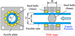
Figure 1. Flexible pneumatic cylinder.

Figure 2. Appearance of flexible spherical actuator.
stages with his or her hands. The actuator can also provide movement to the upper limb. However, to realize the desired motion, it is necessary to measure the relative coordinates between both stages. Figure 3 shows a transient view of the spherical actuator. The supply pressure is 450 kPa. From Figure 3, it can be seen that the actuator can create different attitudes easily. In addition, with regard to the movement of both arms, we found that the actuator provided motion for not only the wrist but also the arms. Generally, a passive exercise such as the proposed motion is useful in recovering the moving areas of joints and the functions of nerves and muscles. However, as patients must use the device alone, it is better to observe a relative position between both handing stages in order to prevent to occur a crash accident of the patient’s hands.
3. Low-Cost Wire-Type Linear Potentiometer
In order to measure the displacement of the flexible pneumatic cylinder directly, a low-cost wire-type linear potentiometer was proposed and developed in our previous study [13] . A wire-type liner encoder on the market is well known as a displacement sensor with a long stroke measurement. However, the cost of the encoder is very expensive, approximately 500 US dollars. The measuring resolution of the encoder is too high to apply a position control of the flexible pneumatic cylinder, which is required at a resolution of less than 1 mm. In addition, in order to obtain the displacement from the encoder output, a high-spec built-in embedded controller with faster processing speed is required for processing high-frequency pulse signals from the encoder. Therefore, a low-cost wire-type linear potentiometer whose output analogue signal is easily processed

Figure 3. Transient view of movement of device.
by a tiny embedded controller through an A/D converter was developed. Figure 4 shows the construction of the low-cost wire-type linear potentiometer. The tested potentiometer consists of a helical potentiometer (BOURNS Co. Ltd., 3590S-A26-104L) that can measure 10 times the rotational angle, a clockwork wire spool with a diameter of 22 mm, and a flexible stainless-steel wire with a diameter of 0.4 mm. Both shafts of the potentiometer and the wire spool are connected to each other. From the rotational angle of the helical potentiometer and the diameter of the wire spool, a maximum length for measurement of about 0.7 m can be expected. The resolution of the potentiometer using a 10-bit A/D converter is about 0.74 mm. The cost of the linear potentiometer except for the stainless steel wire is inexpensive at about 8 US dollars. In the previous study, a flexible pneumatic cylinder with built-in wire-type linear potentiometer, wherein the cylinder head was connected to the wire of the tested potentiometer through a special sealing mechanism, was developed [13] . This is shown in Figure 5. Figure 6 shows the transient response of the displacement of the tested cylinder. In Figure 6, the dashed blue line and solid red line indicate the desired and controlled displacements of the tested cylinder, respectively. The sampling period of position control is 1 ms. From Figure 6, it can be confirmed that the position of the cylinder can be controlled by using the tested sensor. However, the relative coordinates between both stages cannot be measured by using the displacement sensor of the flexible pneumatic cylinder because of the lower stiffness of the spherical actuator.
As mentioned above, the displacement of the cylinder was successfully measured. However, in order to apply the spherical actuator to rehabilitation devices, it is required to measure not only the displacement of the flexible pneumatic cylinder but also the relative coordinates between both handling stages because of the flexibility of the spherical actuator. Therefore, a low-cost 3D coordinate measuring device that can be applied to rehabilitation devices was proposed and tested [11] .
4. Three-Dimensional Coordinate Measuring Device
Figure 7 shows a 3D coordinate measuring device using the three improved

Figure 4. Low-cost wire-type linear potentiometer.

Figure 5. Flexible pneumatic cylinder with wire-type linear potentiometer and special sealing mechanism.
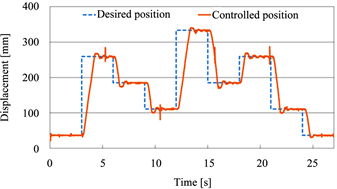
Figure 6. Transient response of displacement of cylinder for multi-position control.
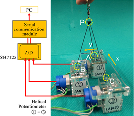
Figure 7. Three-dimensional coordinate measuring device.
wire-type linear potentiometers described below. In the device, the ends of the wires of each potentiometer are connected to each other. Each wire outlet position (A, B, and C) is arranged such that each distance from the measuring origin is kept at a certain distance d. Figure 8 shows the measuring model of the device. From a geometric relationship, the following equations related to the distance d and coordinates of the measuring point P (x, y, z) can be obtained:
, (1)
, (2)
. (3)
Equations (4) to (6) are derived from Equations (1) to (3).
, (4)
, (5)
. (6)
From Equations (4) to (6), it can be seen that the coordinates can be obtained by measuring each distance DA, DB, and DC.
In order to realize a low-cost 3D measuring system, the wire-type linear potentiometer is useful because the estimated cost of its parts is less than 10 US dollars. However, the tested linear potentiometer has a slight problem in that the rotary shaft of the spool and the helical potentiometer are not connected directly. This flexible connection of both shafts causes a measuring error. In addition, to measure the relative coordinates between the handling stages of the actuator based on the principle of triangulation, it is necessary to realize a high-resolution measurement in the appropriate range. Thus, an improved wire-type linear potentiometer as shown in Figure 9 was proposed and tested. Compared with the previous potentiometer, the spool is directly connected to the shaft of the potentiometer. Accordingly, this realized a smooth motion. Further, the diameter of the clockwork wire spool was shortened from 22 mm to 10 mm. As a result, the resolution of the sensor was improved to 0.45 mm. The size of the potentiometer became smaller, at 30 mm in height, 30 mm in width, and 42 mm in length. The mass of the potentiometer was 44 g. The maximum length for measurement was about 260 mm.
Figure 10 shows an experimental setup of the 3D measuring device to investigate the measuring accuracy of the device. The experimental setup consists of the tested 3D measurement device and two kinds of ring-shaped disks with different inner diameters of 100 mm and 160 mm. Two disks are set on the base plate at various heights by using spacer rods. In the experiment, the tip of the measuring device moves along the inner bore of the disks.
Figure 11 shows the experimental results of the 3D coordinate measurement

Figure 8. Measuring model of device.

Figure 9. View of improved wire type linear potentiometer.

Figure 10. Experimental setup of 3D measuring device.
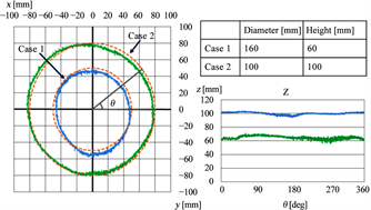
Figure 11. Experimental results using tested device.
using the tested device. In the experiment, the tip of the device was moved from 0 to 360 degrees of rotation angle θ along the inner bores of disks with two kinds of diameters; 160 mm and 100 mm. In Figure 11, solid and dashed lines indicate the trajectory of the measuring point and the true value, respectively. From Figure 11, it can be seen that the device can measure the coordinates within an error of 5 mm. This measuring accuracy is sufficient to apply the spherical actuator, which does not require precise positioning.
5. Spherical Actuator with Built-in 3D Coordinate Measuring Device
In order to install the 3D coordinate measuring device in the spherical actuator, the size of the device is very important. Therefore, a built-in 3D coordinate measuring device is proposed and tested. Figure 12(a) and Figure 12(b) show the entire spherical actuator and the built-in 3D coordinate measuring device, respectively. As shown in Figure 12(b), by changing the setting direction of each wire-type linear potentiometer, a compact 3D coordinate measuring device can be realized even if the distance from the measuring origin to each wire start point is kept at the same distance d of 35 mm. This means that each wire outlet position is the same as that of the previous device shown in Figure 7. The measuring device is 100 mm in length, 47 mm in width, and 36 mm in height. The mass of the measuring device is approximately 165 g. The required space for setting the device decreased to 46% of the previous one. From Figure 12(a), the device is set so as to meet both coordinates of the device and actuator each other.
Figure 13 shows a schematic diagram of the position control system of the tested flexible spherical actuator. The control system consists of the spherical actuator with the 3D coordinate measuring device, four quasi-servo valves [14] to operate the two flexible pneumatic cylinders and an embedded controller (Renesas Co. Ltd., SH7125). Position control of the device is accomplished as follows. First, the embedded controller receives output voltages from three wire-type potentiometers, and the coordinates of the measuring point (x, y) are calculated. By comparing them with the desired position set in advance, the deviation from the desired position can be calculated. As a control scheme, the following simple proportional control scheme was used:
( ), (7)
( ), (8)
where ui, ri, ci, and di are the control input, desired coordinates and the measured coordinates for the x and y directions, and the input duty ratio of the PWM valve, respectively. The switching valves are changed based on the negative or positive value of the control input ui. The input duty ratio for PWM valve di is added 22.5% to compensate the dead zone of the valve [14] . By this method, the quasi-servo valves are driven and the flexible pneumatic cylinders are controlled in the x and y directions independently. In the control, a sampling period of 5 ms was used. The PWM period of the quasi-servo valve was 10 ms.
Figure 14 shows the transient response of the x and y coordinates of the handling stage in the tracking position control. In Figure 14, the dashed and solid lines show the desired coordinates and controlled position in the x and y directions, respectively. Figure 15 shows the attitude of the actuator for each desired position in Figure 14. In this case, the same desired coordinate was given for both the x and y directions. From Figure 14, it can be seen that the position of the cylinder can be controlled by using the feedback signal from the 3D coordinate measuring device. However, we observe a non-negligible error between the desired and measured position. The positioning accuracy of the device will be improved by using a control scheme that compensates for the frictional force and time delay of the actuator.


Figure 12. Flexible spherical actuator with built-in 3D coordinate measuring device. (a) View of entire actuator; (b) Built-in 3D coordinate measuring device.
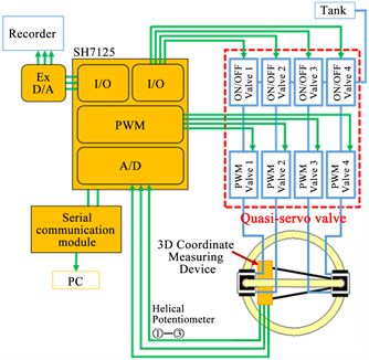
Figure 13. Position control system of device.
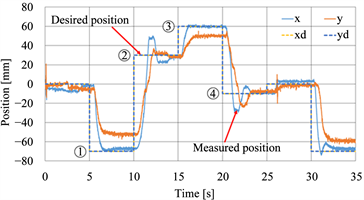
Figure 14. Transient response of x and y coordinates of handling stage.
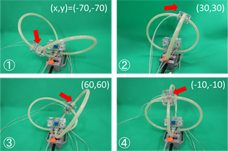
Figure 15. Attitude of actuator for each desired position in Figure 14.
6. Conclusion
In order to prevent the crash accident of patient’s hands, a 3D coordinate measuring device that can obtain the relative coordinates between two stages in a flexible spherical actuator was proposed and tested. The measuring device consists of three wire-type linear potentiometers and an embedded controller. To confirm the validity of the device, preliminary measurements using the theoretical model were carried out. As a result, it was confirmed that the tested device could measure the coordinates between both handling stages within an error of 5 mm. A spherical actuator with a built-in 3D coordinate measuring device was also constructed. The tracking position control of the actuator using the measuring device was carried out. We confirmed that the position of the cylinder can be controlled by using the feedback signal from the tested device. In our future work, we will focus on improving the positioning accuracy by applying a control scheme while compensating the frictional force and time delay of the actuator.
Acknowledgements
This study was supported by the Education Ministry of Japan through the Financial Assistance Program for QOL Innovative Research (2012-2016) and a Grant-in-Aid for Scientific Research (C) (Subjects 16K06202 & 17J09802).
Cite this paper
Matsui, Y., Akagi, T., Dohta, S., Kobayashi, W. and Tamaki, H. (2018) Development of Flexible Spherical Actuator with 3D Coordinate Measuring Device. Journal of Flow Control, Measurement & Visualization, 6, 95-106. https://doi.org/10.4236/jfcmv.2018.62009
References
- 1. Ishii, M., Yamamoto, K. and Hyodo, K. (2005) Stand-Alone Wearable Power Assist Suit-Development and Avail-Ability. Journal of Robotics and Mechatronics, 17, 575-583. https://doi.org/10.20965/jrm.2005.p0575
- 2. Noritsugu, T., Takaiwa, M. and Sasaki, D. (2009) Development of Power Assist Wear Using Pneumatic Rubber Artificial Muscles. Journal of Robotics and Mechatronics, 21, 607-613. https://doi.org/10.20965/jrm.2009.p0607
- 3. Kobayashi, H., Shiban, T. and Ishida, Y. (2004) Realization of All 7 Motions for the Upper Limb by a Muscle Suit. Journal of Robotics and Mechatronics, 16, 504-512. https://doi.org/10.20965/jrm.2004.p0504
- 4. Nagata, Y., Ed. (2004) Soft Actuators -Forefront of Development. NTS Ltd., Tokyo, 291-335.
- 5. Akagi, T. and Dohta, S. (2007) Development of a Rodless Type Flexible Pneumatic Cylinder and Its Application Transactions of JSME, Series C, 73, 2108-2114.
- 6. Aliff, M., Dohta, S., Akagi, T. and Li, H. (2012) Development of a Simple-Structured Pneumatic Robot Arm and Its Control Using Low-Cost Embedded Controller. Journal of Procedia Engineering, 41, 134-142. https://doi.org/10.1016/j.proeng.2012.07.153
- 7. Dohta, S., Akagi, T., Liu, C. and Ando, A. (2013) Development and Control of Flexible Spherical Actuator Using Flexible Pneumatic Cylinders. International Journal of Advanced Mechatronic Systems, 5, 184-192. https://doi.org/10.1504/IJAMECHS.2013.057441
- 8. Krebs, H.I., et al. (2007) Robot-Aided Neurorehabilitation: A Robot for Wrist Rehabilitation. IEEE Transactions on Neural Systems and Rehabilitation Engineering, 15, 327-335. https://doi.org/10.1109/TNSRE.2007.903899
- 9. Takaiwa, M. and Noritsugu, T. (2005) Development of Wrist Rehabilitation Equipment Using Pneumatic Parallel Manipulator. Proceedings of the 2005 IEEE International Conference on Robotics and Automation, Barcelona, 18-22 April 2005, 2302-2307. https://doi.org/10.1109/ROBOT.2005.1570456
- 10. Takaiwa, M. (2016) Wrist Rehabilitation Training Simulator for P.T. Using Pneumatic Parallel Manipulator. 2016 IEEE International Conference on Advanced Intelligent Mechatronics, Banff, 12-15 July 2016, 276-281. https://doi.org/10.1109/AIM.2016.7576779
- 11. Matsui, Y., Akagi, T., Dohta, S., Kobayashi, W. and Tamaki, H. (2017) Development of Simple 3D Measuring Device Using Low-Cost Wire Type Linear Potentiometer for Flexible Spherical Actuator. International Journal of Mechanical Engineering and Robotics Research, 6, 215-218. https://doi.org/10.18178/ijmerr.6.3.215-218
- 12. Kobayashi, W., Guo, J., Akagi, T., Dohta, S. and Kato, N. (2017) Development of Simplified Wearable Wrist Rehabilitation Device Using Low-Friction Type Flexible Pneumatic Cylinders. International Journal of Mechanical Engineering and Robotics Research, 6, 253-257. https://doi.org/10.18178/ijmerr.6.3.253-257
- 13. Matsui, Y., Akagi, T. and Dohta, S. (2016) Development of Low-Cost Wire Type Linear Potentiometer for Flexible Spherical Actuator. 2016 IEEE International Conference on Advanced Intelligent Mechatronics (AIM), Banff, AB, 12-15 July 2016, 1017-1021. https://doi.org/10.1109/AIM.2016.7576903
- 14. Moriwake, Y., Akagi, T., Dohta, S. and Zhao, F. (2012) Development of Low-Cost Pressure Control Type Quasi-Servo Valve Using Embedded Controller. Journal of Procidia Engineering, 41, 493-500. https://doi.org/10.1016/j.proeng.2012.07.203
Nomenclature
ci measured coordinate (I = x, y)
d distance between a wire outlet position and a measuring origin
di input duty ratio of the PWM valve
DA distance between position A and measuring point P
DB distance between position B and measuring point P
DC distance between position C and measuring point P
kp proportional gain
ri desired coordinate (I = x, y)
ui control input (I = x, y)