Journal of Flow Control, Measurement & Visualization
Vol.02 No.02(2014), Article ID:44769,11 pages
10.4236/jfcmv.2014.22008
Evaluation of Characteristics of Phase Change Heat Transfer in Ultrafine Cryoprobe
Junnosuke Okajima, Atsuki Komiya, Shigenao Maruyama
Institute of Fluid Science, Tohoku University, Sendai, Japan
Email: okajima@pixy.ifs.tohoku.ac.jp
Copyright © 2014 by authors and Scientific Research Publishing Inc.
This work is licensed under the Creative Commons Attribution International License (CC BY).
http://creativecommons.org/licenses/by/4.0/


Received 10 January 2014; revised 5 March 2014; accepted 12 March 2014
ABSTRACT
To reduce the invasiveness of cryosurgery, a miniaturized cryoprobe is necessary. The authors have developed an ultrafine cryoprobe for realizing low-invasive cryosurgery by local freezing. The objectives of this study are to estimate the heat transfer coefficient and investigate the characteristics of the phase change heat transfer in the ultrafine cryoprobe. This cryoprobe has a double-tube structure consisting of two stainless steel microtubes. The outer diameter of the cryoprobe was 550 μm. The alternative Freon HFC-23, which has a boiling point of −82˚C at 0.1 MPa, was used as a refrigerant. To evaluate the characteristics of boiling flow in the cryoprobe, the heat transfer coefficient was estimated. The derived heat transfer coefficient was higher than that obtained from the conventional correlation. Additionally, a bubble expansion model was introduced to evaluate the heat transfer mode of the phase change flow in the ultrafine cryoprobe. This model can estimate the liquid film thickness during the expansion of a single bubble in a microchannel. The experimentally measured wall superheat was much lower than that obtained from the model. Therefore, this result also implied that the heat transfer mode in the ultrafine cryoprobe should be nucleate boiling.
Keywords:
Phase Change Heat Transfer, Biomedical Application, Cryosurgery, Microchannel

1. Introduction
Cryosurgery is a surgical treatment that uses the characteristics of frozen biological tissue to remove undesirable tissues using a cooling device called a cryoprobe. Cryosurgery is less invasive and offers the advantages of low bleeding and a short recovery period [1] .
Some cryoprobes have succeeded commercially, e.g., Accuprobe from Cryomedical Science [2] , CRYOcare from ENDOcare [3] , ERBOKRYO from ERBE [4] , CryoHit from Galil Medical [5] , and SurgiFrost from CryoCath Technologies [6] . Conventional cryoprobes, which are classified into two types depending on the cooling method used, are 3 - 8 mm in diameter. Hence, it has been difficult to treat small lesions, such as pigments on the skin, wrinkles around the eyes, and early breast cancer, by conventional cryoprobes.
Several cryoprobes have been proposed that reduce the level of invasiveness. Takeda et al. [7] developed a Peltier cryoprobe. By changing the electric current supplied to a Peltier module, the surface temperature of the cooling section can be controlled precisely. Aihara et al. [8] developed a flexible, long, slender cryoprobe with vacuum insulation. Boiling heat transfer of an impinging jet using liquid nitrogen was used as the heat transfer mechanism. Additionally, Maruyama et al. [9] developed a flexible cryoprobe that uses the Peltier effect. This cryoprobe consists of a flexible plastic tube. Additionally, miniaturized cryoprobes of around 1 mm diameter have been studied by Benita and Condé [10] and Zhang et al. [11] ; however, the cooling power of those cryoprobes was insufficient because the heat transfer rate decreased owing to the large ratio of the surface area to the volume. Generally, the miniaturization of channel size causes increasing the heat transfer coefficient and decreasing the heat transfer rate comparing to the normal size. Therefore, a mechanism to achieve the both of high heat transfer coefficient and transporting large amount of heat is required and the solution is using the phase change heat transfer.
To overcome this problem, the authors have studied the phase change heat transfer in a co-axial small double tube [12] and developed an ultrafine cryoprobe with boiling heat transfer in a microchannel [13] [14] . The outer diameter of this cryoprobe is 550 μm. The ultrafine cryoprobe may realize new cryosurgery for small lesions with minimum invasiveness, or in a blood vessel using a catheter. In previous study, the theoretical limitation of freezing size by the ultrafine cryoprobe [14] and the refrigerant state inside the cryoprobe [13] were discussed. To realize small-scale cryosurgery using the ultrafine cryoprobe, its cooling performance needs to be clarified. Especially, the heat transfer coefficient is the important parameter to evaluate the cooling performance. The objectives of this study are to estimate the heat transfer coefficient and evaluate the characteristics of the phase change heat transfer in the ultrafine cryoprobe by using the estimated heat transfer coefficient.
2. Experimental System
2.1. Ultrafine Cryoprobe
Figure 1 shows the concept of the ultrafine cryoprobe, which consists of inner and outer tubes. The inner tube has a 150 μm outer diameter (OD) and a 70 μm inner diameter (ID). The outer tube has a 550 μm OD and 300 μm ID. Both tubes are made of stainless steel. HFC-23, which is an alternative Freon with a normal boiling point of −82.1˚C, was used as a refrigerant. HFC-23 was transported to the inner tube in the liquid state.
The inner tube acts as a capillary for depressurization. Therefore, a large pressure drop occurs in the inner tube, and the temperature of the refrigerant decreases. Furthermore, the refrigerant expands upon exiting the inner tube. Here, the refrigerant changes to a two-phase flow, and the outer tube is cooled. The advantages of this
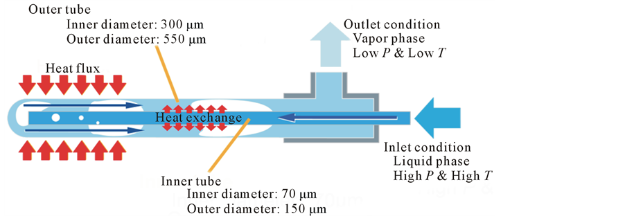
Figure 1. Concept of ultrafine cryoprobe.
cooling system are as follows:
1) The refrigerant can be transported from the reservoir to the cooling section. Therefore, a complex insulation system such as that used in liquid nitrogen cryoprobes is not required.
2) The ultrafine cryoprobe is cooled by boiling heat transfer. Therefore, a higher heat transfer coefficient than that of Joule-Thomson cryoprobes can be expected.
3) Generally, the cryoprobe is required to generate lower than −20˚C in order to necrotize an affected area. The size of necrosis area and required heat flux can be predicted by solving the freezing phenomena of biological tissue.
2.2. Experimental System
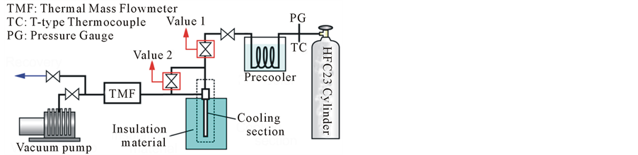
Figure 2 shows the experimental apparatus, which consists of an HFC-23 cylinder, a precooler, several valves, and the cooling section. The measurements were made using T-type thermocouples, a pressure gauge, and a thermal mass flowmeter. The locations of each sensor are shown in Figure 2(b), which also shows the details of the ultrafine cryoprobe section. The refrigerant temperature and pressure at the inlet and outlet were measured by a T-type thermocouple 76 μm in diameter and the pressure transducer, respectively. Nine T-type thermocouples were installed on the ultrafine cryoprobe surface using a thermally conductive, electrically insulating adhesive. Moreover, a leading wire was soldered to the cryoprobe’s surface to supply the electrical voltage for controlling the heat flux. The surface of the ultrafine cryoprobe was insulated by Styrofoam [Dow Chemical Company, thermal conductivity = 0.03 W/(m・K)].
Before the experiment, the air in the experimental apparatus was evacuated by a vacuum pump. During evacuation, the needle section was heated by applying a direct current to remove any remaining water vapor. The HFC-23 tank was kept at room temperature. The precooler was cooled by ice water. The HFC-23 vapor from the tank passed through the precooler, and HFC-23 condensed from the vapor phase to the liquid phase. Before the experiment began, Valve 2 was opened to bring the pressure inside the needle section to 0.1 MPa and release the pressure inside the cryoprobe. Then the experiment was started by opening Valve 1.
3. Experimental Results
Figure 3 shows the time variation in the temperature and mass flow rate without heating by the electric current. The surface temperature of the ultrafine cryoprobe decreased immediately and then remained constant at around −50˚C. In previous study [13] , the vapor quality in the tip of cryoprobe was estimated as the slightly subcooled liquid. By assuming that the refrigerant in outer tube is saturated, the pressure in the tip of cryoprobe is estimated at around 0.5 MPa. Therefore, the pressure drop in the inner tube is 3.7 MPa. Additionally, the refrigerant temperature in the outlet decreased gradually. This result indicates that the refrigerant exhaust from the outer tube was capable of cooling.
Figure 4 shows the time variation in the surface temperature with a heat flux of 100 kW/m2. The temperature increased by only 2 K after heating by the electric current. Figure 5 shows the time variation in the surface temperature with a heat flux of 170 kW/m2. In this case, the temperature increased by 5 to 7 K after heating by the electric current. Additionally, the temperature response at TC9 was slightly fluctuated. This fluctuation indicated that the partial dryout should occur in the cryoprobe. These two figures proves that the phase change heat
 (a) (b)
Figure 2. Schematic of experimental system, (a) Overview of system, (b) Detail of cooling section.
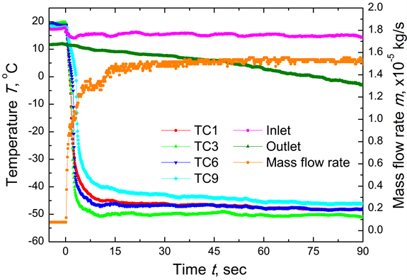
Figure 3. Time variation in temperature at TC1, TC3, TC6, TC9, inlet, and outlet and mass flow rate [14] .

Figure 4. Time variation in temperature at TC1, TC3, TC6, TC9, inlet, and outlet and mass flow rate under heat flux of 100 kW/m2 [14] .
transfer of HFC-23 has a large cooling power.
Figure 6 shows the time variation in the surface temperature with a heat flux of 180 kW/m2. The temperature increased by only 5 to 7 K after heating by the electric current. This trend was as same as the case of 170 kW/m2. However, as shown in Figure 7, the unstable response of the time variation in the surface temperature was observed at TC8 when a heat flux of 180 kW/m2 was supplied. These unstable phenomena occurred accidentally. As shown in Figure 7, the instability started on the downstream side. The temperature at TC9 was around −5˚C. In this location, the refrigerant was completely superheated by the external heat flux. On the other hand, a constant temperature was maintained near the tip of the ultrafine cryoprobe. Therefore, the edge of liquid film should exist around the location of TC8 and the wetting and drying should occur periodically at this location.
This temperature fluctuation shown in Figure 7 should not affect to the freezing process in the cryosurgery. The temperature of frozen region should not follow the fluctuation because the heat capacity of frozen tissue is large. The problem in the real application is the refrigerant temperature and time-averaged heat transfer coefficient. Next, the heat transfer coefficient of the ultrafine cryoprobe was derived using the stable temperature data under heating.

Figure 5. Time variation in temperature at TC1, TC3, TC6, TC9, inlet, and outlet and mass flow rate under heat flux of 170 kW/m2.

Figure 6. Time variation in temperature at TC1, TC3, TC6, TC7, TC8, TC9, inlet, and outlet, and in mass flow rate under heat flux of 180 kW/m2.
4. Heat Transfer Coefficient
To consider the heat conduction in the channel wall, the one-dimensional axisymmetric heat conduction equation was solved. This equation with volumetric heat generation  in the steady state is expressed as
 . (1)
. (1)
The boundary conditions can be written as
 , (2)
, (2)
 . (3)
. (3)
By solving Equation (1) analytically, the wall superheat and heat transfer coefficient can be expressed as
 , (4)
, (4)
 , (5)
, (5)
where : heat transfer coefficient [W/(m2・K)],
 : thermal conductivity of stainless steel [W/(m・K)],
 : heat flux [W/m2],
 : inner radius of outer tube[m] and
 : outer radius of outer tube [m]. By using Equations (4) and (5), the wall superheat and heat transfer coefficient can be determined from the experimental data.
Figure 8 shows the wall superheat distribution on the cryoprobe surface derived using Equation (4). The wall superheat decreases slightly along the channel. This result indicates that heat conduction through the wall may affect the wall superheat. The heat flux of 150 kW/m2 shows the highest wall superheat. Figure 9 shows the heat transfer coefficient distribution on the ultrafine cryoprobe surface derived using Equation (5). The heat transfer coefficient obviously increases along the channel, and the location changes dramatically at more than 30 mm. In this region, the axial heat conduction has a strong effect. Therefore, the representative wall superheat and heat transfer coefficient were determined by averaging the value sat locations of less than 30 mm.
Figure 10 shows the relationship between the heat transfer coefficient, wall superheat, and heat flux. Additionally, the estimated heat transfer coefficients are compared with Li’s correlation [15] , which is the correlation of the heat transfer coefficient of phase change flow in mini/microchannels, expressed as
 , (6)
, (6)
where : thermal conductivity of the liquid phase [W/(m・K)],
 : Nusselt number,
 : boiling number,
 : Bond number and
 : Reynolds number of the liquid phase, which are expressed as
 (7)
(7)
where : mass flux [kg/(m2・s)],
 : latent heat [J/kg],
 : gravitational acceleration [m/s2],
 : density of the liquid phase [kg/m3],
 : density of the vapor phase [kg/m3],
  surface tension [N/m],
 : vapor quality
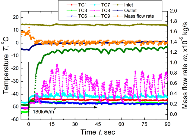
Figure 7. Unstable response in temperature at TC1, TC3, TC6, TC7, TC8, TC9, inlet, and outlet, and in mass flow rate under heat flux of 180 kW/m2.
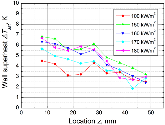
Figure 8. Wall superheat distribution on cryoprobe surface (Location z = 0 represents tip of cryoprobe).
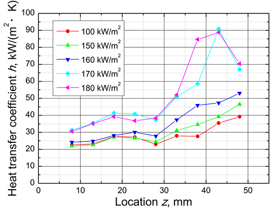
Figure 9. Heat transfer coefficient distribution on cryoprobe surface (Location z = 0 represents tip of cryoprobe).
[-] and : viscosity [Pa・s]. As shown in Figure 10, the heat transfer coefficient reaches a maximum value of 39 kW/(m2・K) at a heat flux of 170 kW/m2. Furthermore, the heat transfer coefficient increases dramatically when the heat flux exceeds 150 kW/m2. Compared with the value from Li’s correlation, the experimental value was close to the heat transfer coefficient for low vapor quality under a low heat flux. However, in the high heat flux region, the rate of increase of the experimental results was larger than that from Li’s correlation. This strong dependence on the heat flux is a general tendency of nucleate boiling. Therefore, Figure 10 implies that the heat transfer mode in the ultrafine cryoprobe is nucleate boiling.
5. Mode of Phase Change Heat Transfer in Cryoprobe
To evaluate the phase change heat transfer regime, the bubble expansion model [16] was applied to the ultrafine cryoprobe, as shown in Figure 11. Here, the bubble is assumed to travel at the velocity of the liquid phase and to expand only downstream. In addition, the annular channel of the ultrafine cryoprobe is assumed to be the equivalent circular channel by using the hydraulic diameter.
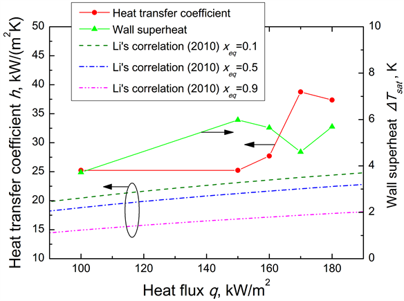
Figure 10. Relationship between heat transfer coefficient, wall superheat, and heat flux.
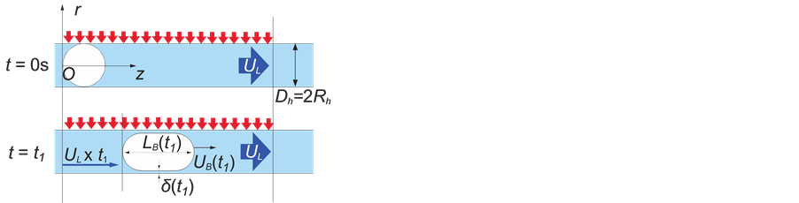
Figure 11. Bubble expansion model.
The energy balance between the bubble volume and supplied heat is expressed as
 , (8)
, (8)
where : bubble volume [m3], D: channel diameter [m],
 : bubble length [m]. The bubble head speed
  is defined as the time derivative of the bubble length as follows:
 . (9)
. (9)
The liquid film thickness is determined by Taylor’s law, which is the correlation between the liquid film thickness and bubble velocity, expressed as
 , (10)
where : liquid film thickness [m],
 : capillary number. This model can calculate the bubble expansion process and the temporal variation in the liquid film thickness during expansion. The heat transfer coefficient can be calculated from the liquid film thickness with following equation as
 .
.
Figure 12 compares the experimentally obtained heat transfer coefficient with the theoretical prediction of the bubble expansion model. The theoretical prediction underestimates the experimental value. Additionally, Figure 13 compares the wall superheat from the experiment with the theoretical prediction of the bubble expansion
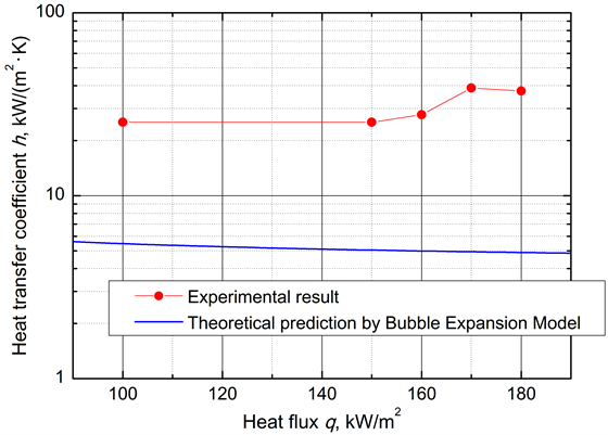
Figure 12. Comparison of heat transfer coefficients estimated from experimental data and from bubble expansion model.
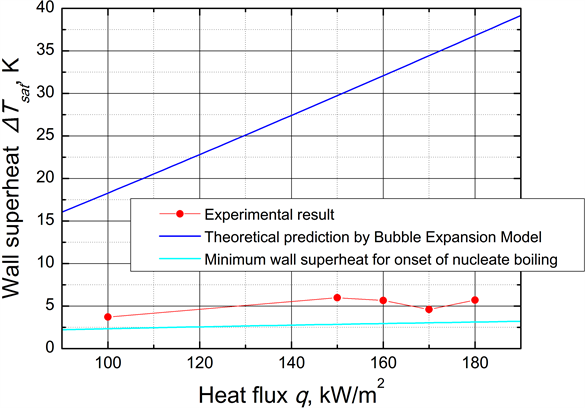
Figure 13. Comparison of wall superheat estimated from experimental data and that estimated from bubble expansion model.
model. The experimental results are much smaller than the theoretical prediction. In addition, the experimental results are larger than the minimum wall superheat for the onset of nucleate boiling [16] . Nucleate boiling does not occur if the wall superheat is less than this minimum value. Actually, it is difficult to measure the size and distribution of the cavity. Therefore, the minimum wall superheat to produce nucleate boiling is an important parameter. This parameter is determined by the relationship between the wall heat flux qw and the wall superheat  to initiate heterogeneous nucleation, which is expressed as [17]
 , (11)
where : gas constatnt [J/(kg・K)],
 : active cavity size [m], and
 : pressure in the liquid phase [Pa]. Therefore, the liquid film thickness predicted by the bubble expansion model is too thick to maintain a low wall temperature. Hence, the heat transfer mode in the ultrafine cryoprobe is not pure evaporative heat transfer from the liquid film. These results may indicate that phase change heat transfer in the ultrafine cryoprobe occurs by nucleate boiling.
6. Conclusions
In this study, the characteristics of phase change heat transfer in an ultrafine cryoprobe were evaluated. The heat transfer coefficient obtained from the experimental data was compared with that obtained from the conventional correlation and the bubble expansion model. The results obtained in this study can be summarized as follows:
1) The ultrafine cryoprobe cooled by HFC-23 exhibited a stable surface temperature of −50˚C.
2) The heat transfer coefficient of the ultrafine cryoprobe was estimated. It reached a maximum value of 39 kW/(m2・K) at a heat flux of 170 kW/m2.
3) By using the bubble expansion model, the phase change heat transfer regime in the ultrafine cryoprobe was estimated. The results may indicate that nucleate boiling occurs in the cryoprobe.
By using the developed cryoprobe, the small-scale cryosurgery will be achieved. We can take advantage of the small size of cryoprobe to treat small lesions, such as pigments on the skin, wrinkles around the eyes, and early breast cancer, with minimal invasiveness. Additionally, the cryosurgery in the blood vessel combined with the catheter is a possible application in the future.
Acknowledgements
J. Okajima received support from a Grant-in-Aid for Young Scientists (B) [25820054] from the Japan Society for the Promotion of Science.
References
- Bischof, J., Christov, K. and Rubinsky, B. (1993) A Morphological-Study of Cooling Rate Response in Normal and Neoplastic Human Liver-Tissue-Cryosurgical Implications. Cryobiology, 30, 482-492. http://dx.doi.org/10.1006/cryo.1993.1049
- Seifert, J.K., Gerharz, C.D., Mattes, F., Nassir, F., Fachinger, K., Beil, C. and Junginger, T. (2003) A Pig Model of Hepatic Cryotherapy. In Vivo Temperature Distribution during Freezing and Histopathological Changes. Cryobiology, 47, 214-226. http://dx.doi.org/10.1016/j.cryobiol.2003.10.007
- Rewcastle, J.C., Sandison, G.A., Saliken, J.C., Donnelly, B.J. and McKinnon, J.G. (1999) Considerations during Clinical Operation of Two Commercially Available Cryomachines. Journal of Surgical Oncology, 71, 106-111. http://dx.doi.org/10.1002/(SICI)1096-9098(199906)71:2<106::AID-JSO9>3.0.CO;2-Z
- Popken, F., Land, M., Bosse, M., Erberich, H., Meschede, P., Konig, D.P., Fischer, J.H. and Eysel, P. (2003) Cryosurgery in Long Bones with New Miniature Cryoprobe: An Experimental in Vivo Study of the Cryosurgical Temperature Field in Sheep. European Journal of Surgical Oncology, 29, 542-547. http://dx.doi.org/10.1016/S0748-7983(03)00069-6
- Tacke, J., Adam, G., Haage, P., Sellhaus, B., Großkortenhaus, S. and Günther, R.W. (2001) MR-Guided Percutaneous Cryotherapy of the Liver: In Vivo Evaluation with Histologic Correlation in an Animal Model. Journal of Magnetic Resonance Imaging, 13, 50-56. http://dx.doi.org/10.1002/1522-2586(200101)13:1<50::AID-JMRI1008>3.0.CO;2-A
- Doll, N., Meyer, R., Walther, T. and Mohr, F.W. (2004) A New Cryoprobe for Intraoperative Ablation of Atrial Fibrillation. The Annals of Thoracic Surgery, 77, 1460-1462. http://dx.doi.org/10.1016/S0003-4975(03)01389-4
- Takeda, H., Maruyama, S., Okajima, J., Aiba, S. and Komiya, A. (2009) Development and Estimation of a Novel Cryoprobe Utilizing the Peltier Effect for Precise and Safe Cryosurgery. Cryobiology, 59, 275-284. http://dx.doi.org/10.1016/j.cryobiol.2009.08.004
- Aihara, T., Kim, J.-K., Suzuki, K. and Kasahara, K. (1993) Boiling Heat Transfer of a Micro-Impinging Jet of Liquid Nitrogen in a Very Slender Cryoprobe. International Journal of Heat and Mass Transfer, 36, 169-175. http://dx.doi.org/10.1016/0017-9310(93)80076-7
- Maruyama, S., Nakagawa, K., Takeda, H., Aiba, S. and Komiya, A. (2008) The Flexible Cryoprobe Using Peltier Effect for Heat Transfer Control. Journal of Biomechanical Science and Engineering, 3, 138-150. http://dx.doi.org/10.1299/jbse.3.138
- Bénita, M. and Condé, H. (1972) Effects of Local Cooling upon Conduction and Synaptic Transmission. Brain Research, 36, 133-151. http://dx.doi.org/10.1016/0006-8993(72)90771-8
- Zhang, J.-X., Ni, H. and Harper, R.M. (1986) A Miniaturized Cryoprobe for Functional Neuronal Blockade in Freely Moving Animals. Journal of Neuroscience Methods, 16, 79-87. http://dx.doi.org/10.1016/0165-0270(86)90010-5
- Okajima, J., Komiya, A. and Maruyama, S. (2010) Boiling Heat Transfer in Small Channel for Development of Ultrafine Cryoprobe. International Journal of Heat and Fluid Flow, 31, 1012-1018. http://dx.doi.org/10.1016/j.ijheatfluidflow.2010.08.008
- Okajima, J., Maruyama, S., Takeda, H., Komiya, A. and Sangkwon, J. (2010) Cooling Characteristics of Ultrafine Cryoprobe Utilizing Convective Boiling Heat Transfer in Microchannel. Proceedings of 14th International Heat Transfer Conference, Washington DC, 8-13 August 2010, 297-306. http://dx.doi.org/10.1115/IHTC14-22550
- Okajima, J., Komiya, A. and Maruyama, S. (2013) 24-Gauge Ultrafine Cryoprobe with Diameter of 550 μm and Its Cooling Performance. Submitted to Cryobiology.
- Li, W. and Wu, Z. (2010) A General Correlation for Evaporative Heat Transfer in Micro/Mini-Channels. International Journal of Heat and Mass Transfer, 53, 1778-1787. http://dx.doi.org/10.1016/j.ijheatmasstransfer.2010.01.012
- Okajima, J., Komiya, A. and Maruyama, S. (2012) Analysis of Evaporative Heat Transfer by Expansion Bubble in a Microchannel for High Heat Flux Cooling. Journal of Thermal Science and Technology, 7, 740-752. http://dx.doi.org/10.1299/jtst.7.740
- Davis, E.J. and Anderson, G.H. (1966) The Incipience of Nucleate Boiling in Forced Convection Flow. AIChE Journal, 12, 774-780. http://dx.doi.org/10.1002/aic.690120426
Nomenclature
 : Channel diameter [m]
 : Mass flux [kg/(m2・s)]
 : Gravitational acceleration [m/s2]
 : Heat transfer coefficient [W/(m2・K)]
 : Latent heat [J/kg]
 : Thermal conductivity [W/(m・K)]
 : Bubble length [m]
 : Pressure [Pa]
 : Heat flux [W/m2]
 : Volumetric heat generation [W/m3]
 : Gas constatnt [J/(kg・K)]
 : Radius, coordinate on radial direction [m]
 : Active cavity size [m]
 : Bubble head speed [m/s]
 : Bubble volume [m3]
 : Vapor quality [-]
 : Coordinate on axial direction [m]
Greek
 : liquid film thickness [m]
 : viscosity [Pa・s]
 : density of the liquid phase [kg/m3]
 : surface tension [N/m]
Dimensionless number
 : Boiling number
 : Bond number
 : Capillary number
 : Nusselt number
 : Reynolds number of the liquid phase
Subscript
 : Inner tube
 : Liquid phase
 : Outer tube
 : Stainless steel