Journal of Flow Control, Measurement & Visualization
Vol. 1 No. 3 (2013) , Article ID: 37601 , 6 pages DOI:10.4236/jfcmv.2013.13013
High Speed Observation of Periodic Cavity Behavior in a Convergent-Divergent Nozzle for Cavitating Water Jet
Department of Mechanical Engineering, Kanazawa Institute of Technology, Nonoichi, Japan
Email: ksato@neptune.kanazawa-it.ac.jp
Copyright © 2013 Keiichi Sato et al. This is an open access article distributed under the Creative Commons Attribution License, which permits unrestricted use, distribution, and reproduction in any medium, provided the original work is properly cited.
Received July 18, 2013; revised August 27, 2013; accepted September 13, 2013
Keywords: Cloud Cavitation; Periodic Behavior; Water Jet; High-Speed Video Observation; Image Analysis
ABSTRACT
Cloud cavitation shows an unsteady periodic tendency under a certain flow condition. In a cavitating water jet flow with cavitation clouds, the cavities or the clouds produce high impact at their collapse. In order to make clear a mechanism of the periodic cavity behavior, we experimentally examine the behavior in a transparent cylindrical convergent-divergent nozzle using a high-speed video camera. An effect of upstream pressure fluctuation due to a plunger pump is investigated from a viewpoint of unsteady behavior in a cavitating water jet. As a result, it is found that the cavitating flow has two kinds of oscillation patterns in the cavity length (cavitation cloud region). One is due to the upstream pressure fluctuation caused by the plunger pump. The other is much shorter periodic motion related to the characteristic oscillation of cavitation clouds accompanied with the shrinking (reentrant), growing and shedding motion of the clouds.
1. Introduction
Cloud cavitation is typically observed in a separated flow field. In many cases, the cloud cavitation shows an unsteady periodic tendency with a periodic shedding of cavitation clouds and a reentrant motion in a cavity. A reentrant motion, for example, can be observed in a sheet cavitation of hydrofoils in high speed liquid flow, where it moves along the surface of the hydrofoil from the trailing edge to the leading edge. Many previous studies have suggested that a reentrant motion is closely related to the shedding of cavitation clouds downstream of cloud cavitation [1-6]. A series of studies made by Franc et al. [6] have been reported, which is about periodic cloud cavitation formed as a partial cavitation on hydrofoils.
A mechanism of the periodic behavior, however, remains unsolved as yet, especially in a water jet nozzle [7- 13]. In a cavitating water jet flow with cavitation clouds, the cavities or the clouds produce high impact at their collapse on an impinged wall. Therefore, important effects on cavitation erosion are pointed out from a viewpoint of pressure waves at the collapse of the clouds [11, 12].
The authors, so far, have studied about a separatedflow cavitation in a convergent-divergent nozzle installed in a closed-type recirculating cavitation tunnel. As a result, it is found that a reentrant motion on the inside of a cavity and the following formation of periodic cloud cavitation are caused by pressure waves occurrence and its propagation due to a collapse of a cavitation cloud shed downstream [2,3].
On the other hand, one of typical examples of other cloud cavitation phenomena is a cavitating water-jet (Cav-WJ). In this case, cloud cavitation is formed at a nozzle exit and a jet boundary. According to Sato et al. [11,12,14] and Yoshida et al. [15], there exist some severe pressure waves in the cloud region of Cav-WJ. It is important to make clear unsteady behavior of cavitation and an effect of pressure waves.
In the present study, the cavitation cloud behavior is investigated using a relatively large convergent-divergent nozzle made of a transparent acrylic-resin cylinder installed in a Cav-WJ apparatus. It is observed that the high-speed water jet accompanied with periodic cavitation clouds is formed in the axisymmetric nozzle. In the present Cav-WJ apparatus, however, there is one subject which is existence of an upstream plunger pump for high pressurization. In general, a water jet apparatus is pressurized by a plunger pump. This kind of high-pressure pump system can affect upstream flow condition due to the periodic pressure pulsation. The unsteady cavity behavior caused by the upstream pressure pump is also experimentally examined together with that by the cavity itself. In the present study, the upstream pressure is limited to a relatively low range in order to restrict the cavity from developing, where the maximum cavity length remains a little downstream of the nozzle exit.
Therefore, in order to make clear a mechanism of periodic cavity behavior, we experimentally examine the behavior in a transparent cylindrical convergent-divergent nozzle using a high-speed video camera. For this, an image analysis method [11,14] is applied to the pictures taken by the high-speed video camera. Especially, an effect of upstream fluctuating pressure (it is accompanied with flow velocity fluctuation) due to the plunger pump is investigated under the unsteady Cav-WJ at various rotational speeds of the pressure pump controlled by an inverter system.
As the result of this experiment, it is found that the cavitating flow has two kinds of periodic behaviors. One is a periodic cloud cavitation related to upstream fluctuation caused by a plunger pump. The other is due to cavitation cloud by nature, which is not affected by plunger unsteadiness.
2. Experimental Method
2.1. Experimental Apparatus
Figure 1 shows a schematic diagram of the experimental apparatus in the present study. Water in the storage tank is pressurized by a high pressure pump and is ejected into the water in the large tank through the cylindrical convergent-divergent nozzle. The experimental tank keeps the water constant height by overflowing the water into the storage tank. The rotational speed of the high pressure pump is controlled by an inverter system.
The unsteady behavior of cavity is observed using a high-speed video camera (Photron, SA5, image size of 64 × 536 pixels at 100,000 fps) which is synchronized with a pressure transducer (JTEKT, PMS-8M-2) installed at 550 mm on the upstream part of the nozzle. The data are then amplified by an amplifier (JTEKT, AA6210) and logged by a data logger (KEYENCE, NR-350) at 25 kHz of sampling frequency. The nominal primary resonance frequency of the pressure transducer is more than 10 - 100 kHz. In the present study, frequencies more than 10 kHz in pressure fluctuation are removed by a low-pass filter. The plane light guide is connected to a light source (a metal halide lamp of 350 W and continuous light, NPI, PCS-UMX 350) and is set in the water at the opposite side of the high-speed camera across the nozzle. The appearance of cavity behavior is taken by means of a back lighting. The high pressure pump (SUGINO MACHINE, JPGM-33036) is a type of 3 plungers and works under a discharge pressure of 30 MPa, a flow rate of 33 L/min and a rotational speed of 340 rpm.
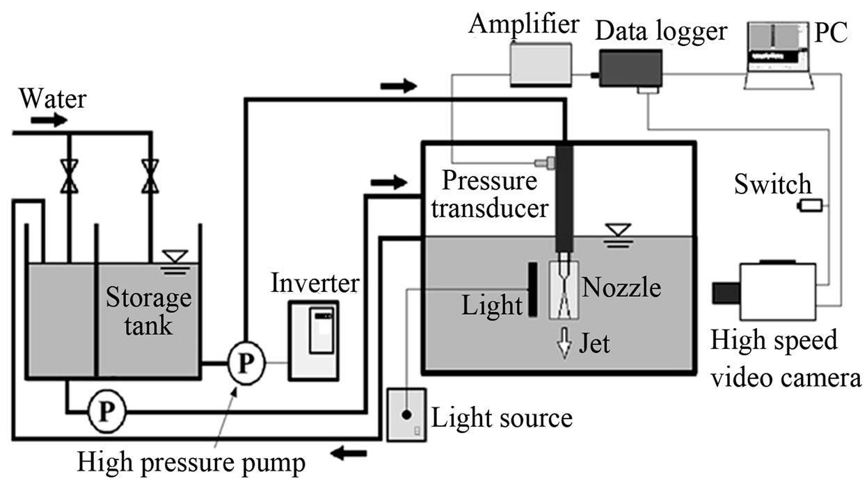
Figure 1. Experimental apparatus.
Figure 2 shows the convergent-divergent nozzle for the Cav-WJ which is made of transparent acrylic resin. The nozzle has a convergent-angle of 90 degree, a divergent-angle of 20 degree and a throat part of 10 mm in length and 1.2 mm in diameter. In addition, the inlet point of the nozzle throat is chosen as origin and the flow direction from the origin is chosen as x-axis. The outer wall of the nozzle has a flat surface, so that the behavior of the cavity in it can be observed clearly.
The experiment was conducted under conditions in which cavitation number σ = 1.2, temperature of water Tw = 297 K, dissolved oxygen content β = 5.5 mg/L and frame speed Fs = 100,000 fps.
2.2. Image Analysis Method
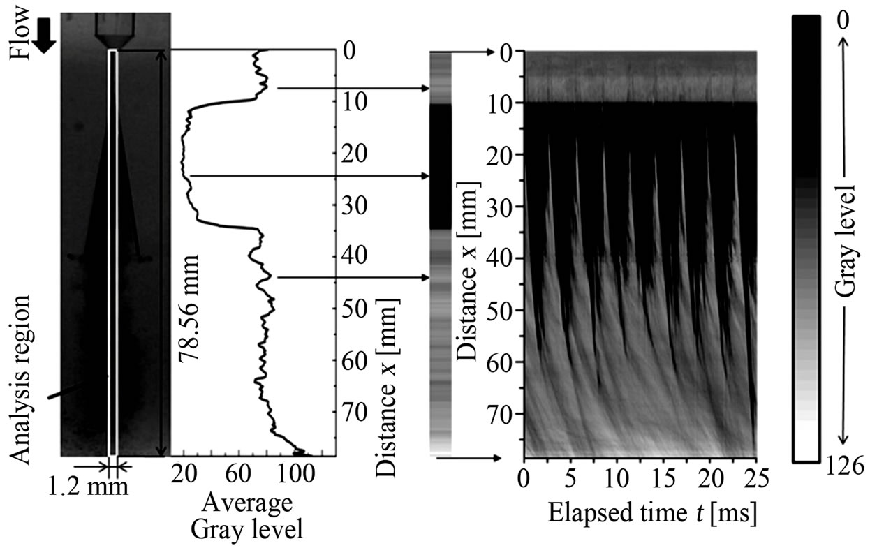
In the present study, an image analysis using a gray level technique is used in order to estimate an existence region of cavities. Figure 3 explains an outline of image analysis method. First, the images taken by the high-speed video camera are converted to gray scales with 256 gradations. Black color shows a value of 0 and white color shows a value of 255. As shown in Figure 3(a), the width of the analysis region is equal to the throat diameter and the height is equal to the length from the inlet of the nozzle throat to the bottom of the image (x = 78.56 mm). In the analysis region, gray level distribution is averaged (over 8 pixels) in the direction normal to the flow direction. A curve of averaged gray level as shown in Figure 3(a) can be obtained through the use of the procedure in the analysis region along the flow direction x per pixel. The above-mentioned procedure is applied to the whole time range with every time interval of 0.01 ms. At the same time, over the whole time range, the values of the distribution of the gray level are colored again as the gray level map, where the maximum value of gray level is chosen to be white (defined as 126) and the minimum value is to be black (defined as 0). The final result on the image analysis between the distance x and the elapsed time t can be obtained in Figure 3(b), where the black regions indicate the existence of clouds or cavities.
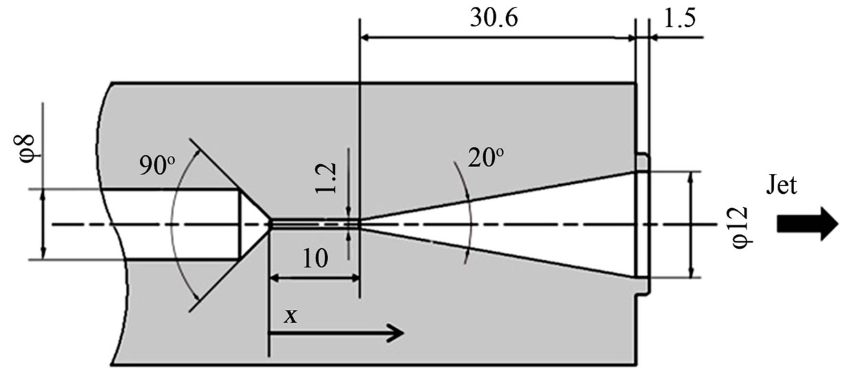
Figure 2. Transparent convergent-divergent nozzle (Unit in mm).
 (a) (b)
Figure 3. Outline of image analysis method used in the present study. (a) Gray level distribution; (b) Change in cavitating zone at t = t1.
3. Experimental Result
3.1. Two Kinds of Fluctuations in Unsteady Flow by Plunger Pump
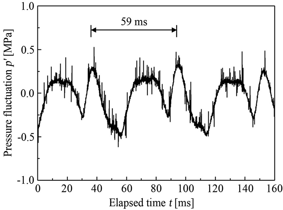
Figure 4(a) indicates a result of upstream pressure fluctuation due to the plunger pump p' and Figure 4(b) is an image analysis result of cavity behavior in the nozzle at the same time scale. Figure 4(b) shows a gray level change in the nozzle at the distance x = 40 mm. The area of cavity existence is colored to be black. It is confirmed that the cloud reaches the distance of x = 40 mm at elapsed time t = 2.5 ms and 5.5 ms, but in the case of t = 1.5 ms and 4.5 ms the cloud does not reach the position x = 40 mm as shown in Figure 5. The one period of upstream pressure fluctuation in Figure 4(a) is estimated to be about 59 ms and its frequency is about 17 Hz which corresponds to three times of pump rotation speed (a pump with 3 plungers is used). Therefore, it is found that the long periodic behavior is caused by the plunger pump.
In addition, it is recognized that the cavity length oscillates in a relatively shorter cycle than the upstream pressure fluctuation. As shown in Figure 4(b), the cavity length oscillates at a constant cycle different from upper pressure fluctuation. The one period of the cavity length oscillation is estimated to be approximately 3.0 ms in this
 (a)
(a)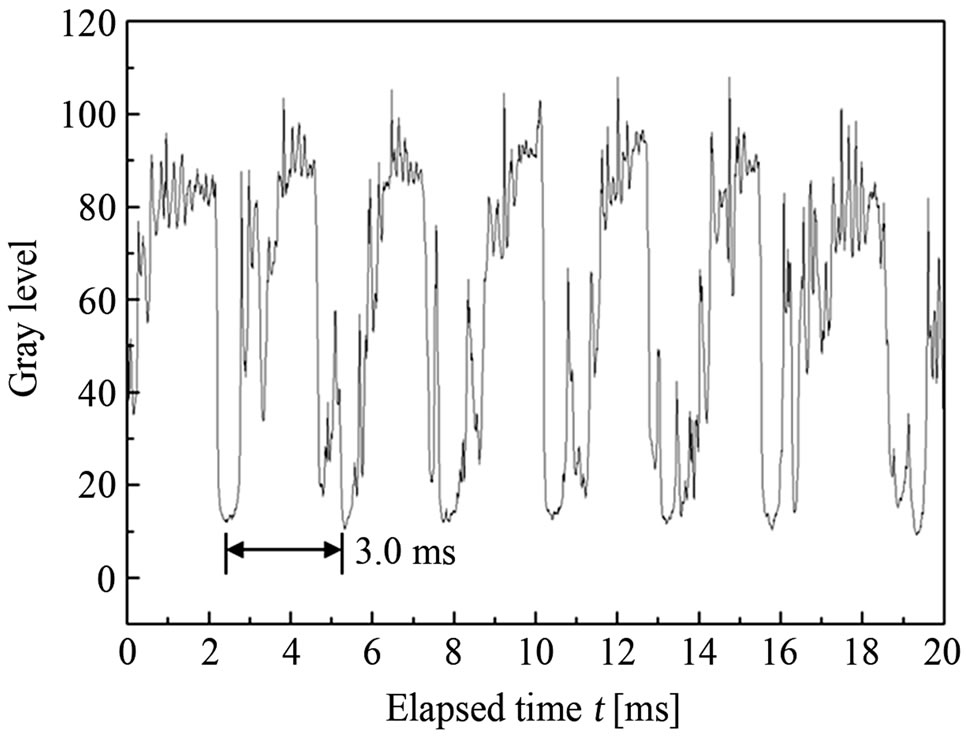 (b)
(b)
Figure 4. Two kinds of oscillation in plunger flow at p = 2.0 MPaG. (a) Upstream pressure fluctuation (due to plunger pump); (b) Gray level change in cavity length.
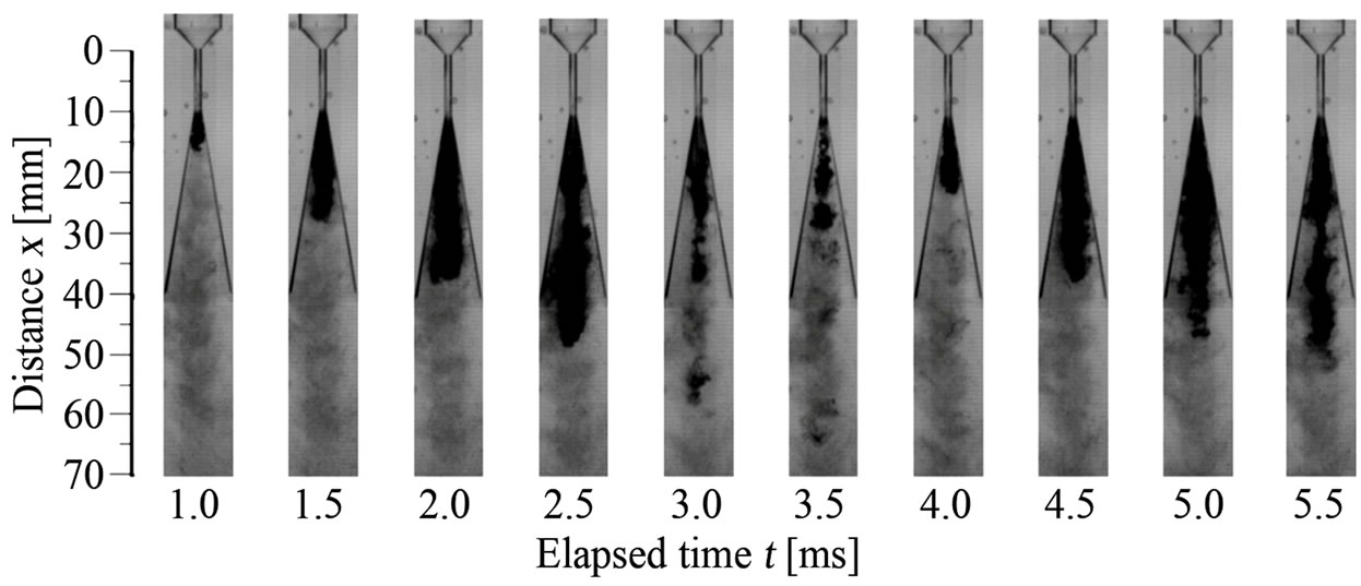
Figure 5. Behavior of cavitation cloud in the nozzle at p = 2.0 MPaG.
case which is much different from that of the upstream pressure fluctuation in Figure 4(a). Also, from the result of FFT analysis indicated in Figure 6, the frequency of cavity length is about 350 Hz while the frequency of the pressure fluctuation is about 18 Hz. In this way, it can be confirmed that the two kinds of oscillations exist in the present flow with the pressure fluctuation due to the plunger pump. The first is upstream pressure fluctuation and the second is cavity length oscillation due to cavitation cloud by nature [16].
3.2. Relation between Upstream Pressure Fluctuation and Cavity Behavior
Figure 7 shows upstream pressure fluctuation p' and the
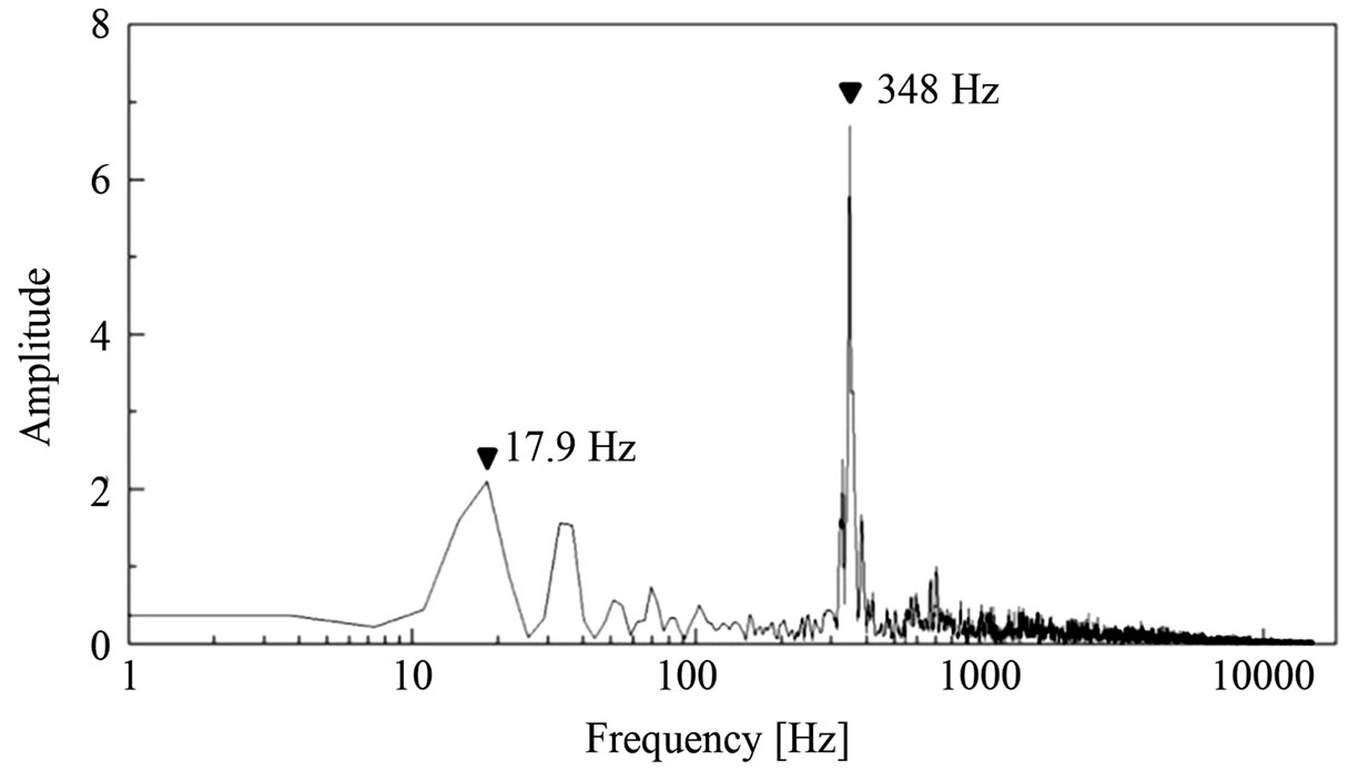
Figure 6. FFT analysis for gray level change in cavity length at p = 2.0 MPaG.
 (a)
(a)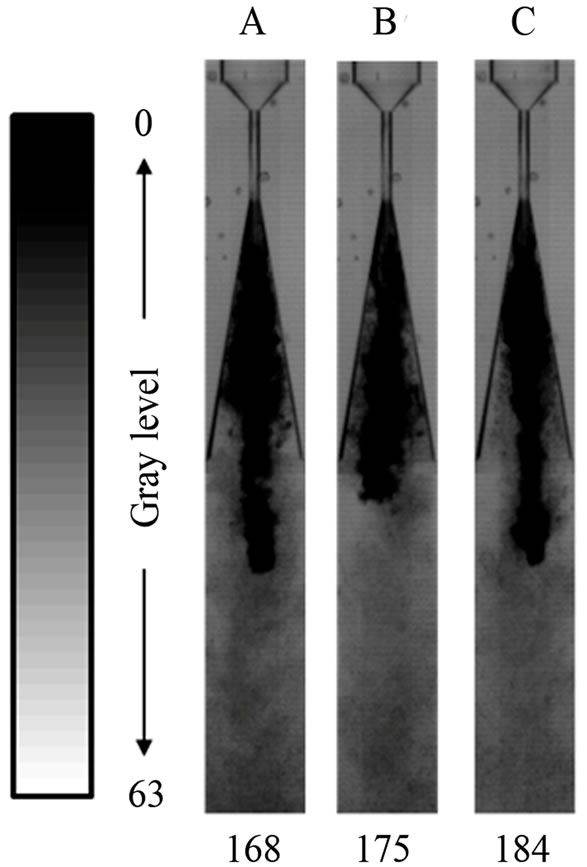 (b)
(b)
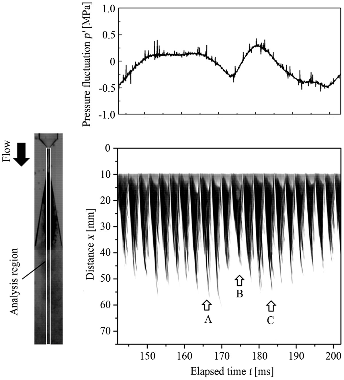
Figure 7. Relation between upstream pressure fluctuation and behavior of cavitation cloud at p = 2.0 MPaG. (a) Change in cavitating zone and upstream pressure fluctuation; (b) Behavior of cavitation cloud due to upstream pressure fluctuation.
behavior of the cavity (cavitation clouds) at upstream pressure p of 2.0 MPaG. Water flows from the upper to the bottom side in the nozzle. Figure 7(a) shows an image analysis result and indicates the change of the cloud region. Figure 7(b) shows pictures about the growing and shrinking motion of the whole cloud region. Here, the black area indicates the existence of clouds under distance x from the nozzle throat inlet against elapsed time t. The elapsed time shown in upstream pressure fluctuation corresponds to that of the image analysis result.
From the results as shown in Figure 7, it is found that the cavity length grows longer when the upstream pressure becomes higher, that is, velocity increases higher (indicated by A and C in Figure 7(a)), and it grows shorter at lower upstream pressure B as shown in Figure 7(a). As a result, it can be confirmed that this kind of change in cavity length is affected by upstream pressure fluctuation as also shown in Figure 7(b). The frequency of upstream pressure fluctuation is almost equal to the rotational speed of the plunger pump. Thus, the upstream pressure fluctuation caused by the pulsation of the plunger pump has an effect on the periodic behavior of cavity length. Therefore, one of the main factors of periodic tendency in cavity length is considered to be upstream pressure fluctuation (and velocity fluctuation accompanied by upstream pressure fluctuation).
3.3. Periodicity of Growth and Collapse of Cavitation Clouds
On the other hand, it can be also recognized that the cavity (cloud region) length has shorter periodic oscillation as well as longer periodic oscillation indicated in Figure 4. In other words, the cavity length changes in a short time range, even when the upstream pressure fluctuation is relatively small. Figure 8 shows detailed successive still pictures taken by the high-speed camera. In these pictures, the collapsing, growing and shedding motions of cavitation clouds are shown at upstream pressure p of 2.0 MPaG and elapsed time t from 23.3 to 27.1 ms. Here, a time interval is chosen as 0.05 ms in the range from 25.1 to 25.9 ms, and is 0.2 ms in the other range. Figure 9 shows the frequency of cavity length oscillation for various upstream pressures p. The standard deviation of the data is estimated to be in the range ±15 Hz. In Figures 8 and 9, it is found that the cavitation clouds repeat a shrinking, growing and shedding motion with the frequency of about 350 Hz.
In Figure 8, the cavities appear at the nozzle throat exit (x = 10 mm) around t = 23.3 ms and then grow in the nozzle diverging area (t = 23.3 - 25.15 ms). Around time of 25.2 to 25.8 ms, it is found that the cavitation cloud is shed downstream and collapses near the nozzle exit (about x = 40 mm). After that, a reentrant motion is observed with a cloud shrinking upstream of the nozzle.
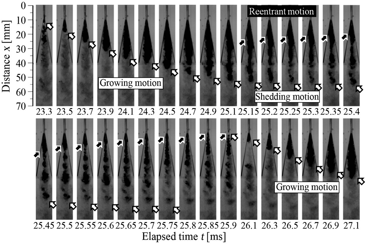
Figure 8. Cavitation cloud oscillation in the nozzle at p = 2.0 MPaG.
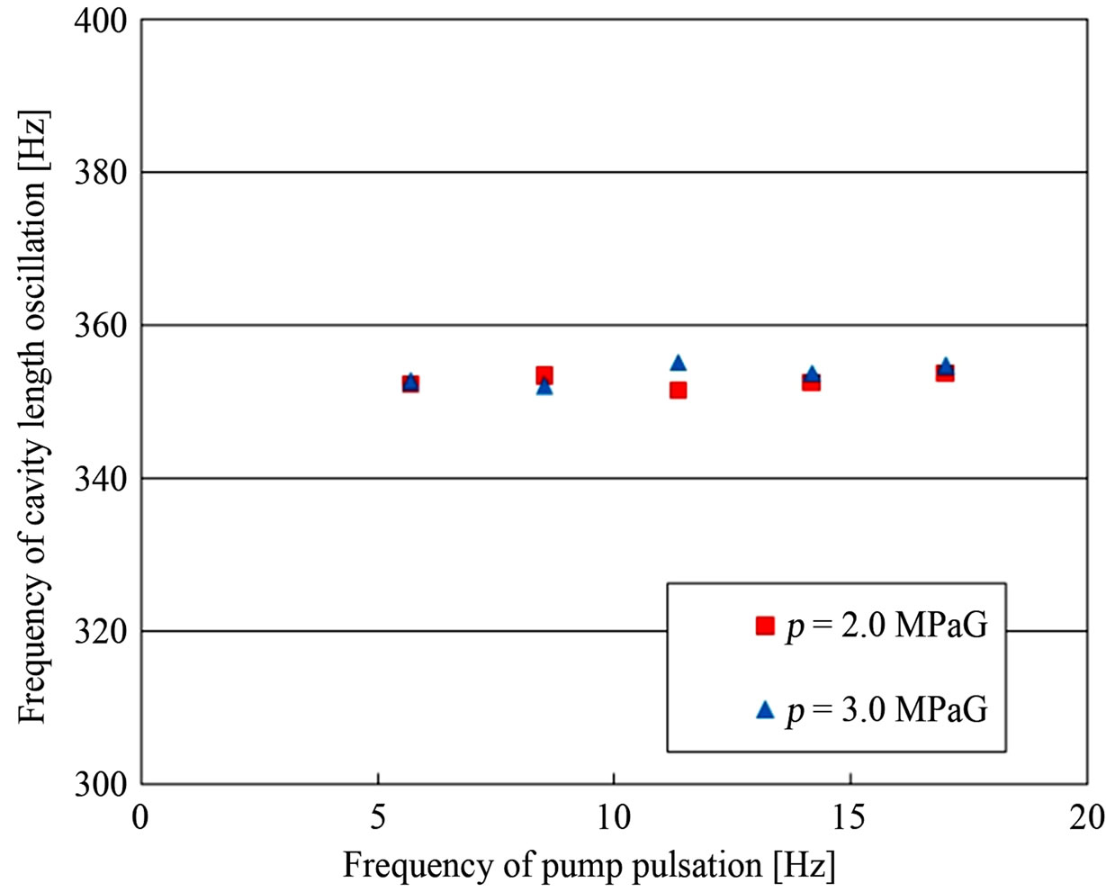
Figure 9. Relation between frequency of pump pulsation and cavity length oscillation.
When the reentrant motion reaches the nozzle throat exit (about t = 25.9 ms), growth of new cavity appears. Thus, the typical pattern of unsteady periodic behavior of cavity [6] can be also recognized in the present study.
As a result, it is observed that there is a shorter periodic behavior of cavity length accompanied with a shrinking, growing and shedding motion of clouds which is caused due to the cavitation cloud unsteadiness by nature [16,17], which is not affected by upstream pressure fluctuation due to the plunger pump. Here, the Strouhal number based on cavity length l (St = nl/u) is estimated to be about 0.28, where u is mean flow velocity at the nozzle throat and n is frequency of cavity length oscillation. Cavity length l is measured at the time right before the cavity breaks away and the shedding motion starts.
4. Conclusions
In the present study about the cylindrical convergent-divergent nozzle, the periodic behavior of unsteady cavitation clouds is investigated from a viewpoint of upstream pressure fluctuation caused by high pressure plunger pump using the high-speed video observation and the measurement of upstream fluctuating pressure.
The main results are as follows.
It is found that there are two patterns of the cavity length (cavitation cloud region) oscillations. One is due to the upstream pressure fluctuation caused by the high pressure plunger pump. The other is shorter periodic oscillation of cavity length. It is found that the shorter periodic fluctuation can be related to the characteristic oscillation of cavitation clouds accompanied with the shrinking (reentrant), growing and shedding motion of cloud.
The trigger mechanism of the reentrant motion remains unsolved at the present stage. As the next step, it is recommended to investigate about the relation between the reentrant motion and the pressure waves accompanied with the cloud shedding.
5. Acknowledgements
The authors would like to thank Dr. Yasuhiro Sugimoto and Dr. Kazuki Niiyama for their kind and helpful advice on this study.
REFERENCES
- R. A. Furness and S. P. Hutton, “Experimental and Theoretical Studies of Two-Dimensional Fixed-Type Cavities,” Journal of Fluids Engineering, Vol. 97, No. 4, 1975, pp. 515-521. http://dx.doi.org/10.1115/1.3448098
- K. Sato, Y. Saito and H. Nakamura, “Self-Exciting Behavior of Cloud-like Cavitation and Micro-Vortex Cavities on the Shear Layer,” Proceedings of the 1st Symposium on Advanced Fluid Information, Sendai, 4-5 October 2001, pp. 263-268.
- K. Sato, Y. Wada, Y. Noto and Y. Sugimoto, “Reentrant Motion in Cloud Cavitation Due to Cloud Collapse and Pressure Wave Propagation,” Proceedings of ASME 2010 3rd Joint US-European Fluids Summer Meeting, Montreal, Quebec, 1-5 August 2010, pp. 7-11.
- M. Sakoda, R. Yakushiji, M. Maeda and H. Yamaguchi, “Mechanism of Cloud Cavitation Generation on a 2-D Hydrofoil,” Proceedings of the 4th International Symposium on Cavitation, Pasadena, 20-23 June 2001, pp. 1-8.
- M. Delar, I. Khlifa, S. Fuzier, M. Adama Maiga and O. Coutier-Delgosha, “Scale Effect on Unsteady Cloud Cavitation,” Experiments in Fluids, Vol. 53, No. 5, 2012, pp. 1233-1250. http://dx.doi.org/10.1007/s00348-012-1356-7
- J. P. Franc and J. M. Michel, “Fundamentals of Cavitation,” Kluwer Academic Publishers, Kluwer, 2004.
- A. Yamaguchi and S. Shimizu, “Erosion Due to Impingement of Cavitating Jet,” Journal of Fluids Engineering, Vol. 109, No. 4, 1987, pp. 442-447. http://dx.doi.org/10.1115/1.3242686
- M. M. Vijay, C. Zou and S. Tavoularis, “A Study of the Characteristics of Cavitating Water Jets by Photography and Erosion,” Proceedings of the 10th International Symposium on Jet Cutting Technology, Amsterdam, 31 October-2 November 1990, pp. 37-67.
- H. Soyama, Y. Yamauchi, Y. Adachi, T. Shindo, R. Oba and K. Sato, “High-Speed Cavitation-Cloud Observations around High-Speed Submerged Water Jets,” Proceedings of the 2nd International Symposium on Cavitation, Tokyo, 5-7 April 1994, pp. 225-230. http://dx.doi.org/10.1115/1.2813125
- E. A. F. Hutli and M. S. Nedeljkovic, “Frequency in Shedding/Discharging Cavitation Clouds Determined by Visualization of a Submerged Cavitating Jet,” Journal of Fluids Engineering, Vol. 130, No. 2, 2008, pp. 1-8. http://dx.doi.org/10.1115/1.2813125
- K. Sato, Y. Sugimoto and S. Ohjimi, “Pressure-wave Formation and Collapse of Cavitation Clouds Impinging on Solid Wall in a Submerged Water Jet,” Proceedings of the 7th International Symposium on Cavitation, Ann Arbor, 16-20 August 2009, pp. 1-11.
- K. Sato, Y. Sugimoto and S. Ohjimi, “Structure of Periodic Cavitation Clouds in Submerged Impinging Water-Jet Issued from Horn-Type Nozzle,” Proceedings of the 9th Pacific Rim International Conference on Water Jetting Technology, Koriyama, 20-23 November 2009, pp. 1-9.
- S. Nishimura, O. Takakuwa and H. Soyama, “Similarity Law on Shedding Frequency of Cavitation Cloud Induced by a Cavitating Jet,” Journal of Fluid Science and Technology, Vol. 7, No. 3, 2012, pp. 405-420. http://dx.doi.org/10.1299/jfst.7.405
- Y. Saito and K. Sato, “Bubble Collapse Propagation and Pressure Wave at Periodic Cloud Cavitation,” Proceedings of the 6th International Conference on Multiphase Flow, Leipzig, 9-13 July 2007, pp. 1-8.
- T. Yoshida, H. Iida, A. Yoshida and K. Yamamoto, “High Speed Observation of Unsteady Behavior of Bubble Clouds Split from Cavitating Jet,” Proceedngs of the 21st International Conference on Water Jetting, Ottawa, 19-22 September 2012, pp. 307-317.
- M. Kjeldsen, R. E. A. Arndt and M. Effertz, “Spectral Characteristics of Sheet/Cloud Cavitation,” Journal of Fluids Engineering, Vol. 122, No. 3, 2000, pp. 481-487.
- K. Sato, S. Shimojo and J. Watanabe, “Observations of Chain-Reaction Behavior at Bubble Collapse Using Ultra High Speed Video Camera,” Proceedings of the ASME/ JSME 2003 4th Joint Fluids Summer Engineering Conference, Honolulu, 6-10 July 2003, pp. 1347-1352. http://dx.doi.org/10.1115/FEDSM2003-45002
Nomenclature
f = Frequency of inverter Fs = Frame speed of high-speed video camera l = Cavity length n = Frequency of cavity length oscillation p = Upstream pressure pv = Saturated vapor pressure of water p’ = Upstream fluctuating pressure St = Strouhal number, nl/u t = Elapsed time of experiment Tw = Temperature of water u = Velocity in throat part of nozzle x = Distance from throat entrance of nozzle
β = Dissolved oxygen content
ρ = Density of water
σ = Cavitation number, 2(p − pv)/ρu2