International Journal of Modern Nonlinear Theory and Application
Vol.3 No.3(2014), Article ID:47870,10 pages
DOI:10.4236/ijmnta.2014.33011
PMSG Wind Energy Conversion System: Modeling and Control
Department of Electric Automatic, National Engineering School of Gabes, Gabes, Tunisia
Email: omessaadbeji@hotmail.fr
Received 22 May 2014; revised 21 June 2014; accepted 4 July 2014
ABSTRACT
In this paper, a model of a variable speed wind turbine using a permanent magnet synchronous generator (PMSG) is presented and the control schemes are proposed. The model presents the aerodynamic part of the wind turbine, the mechanic and the electric parts. Simulations have been conducted with Matlab/Simulink to validate the model and the proposed control schemes. Keywords:Wind Turbine, Wind Energy Conversion System, Permanent Magnet Synchronous Generator, Speed Control, Current Control

1. Introduction
Renewable energy was strongly encouraged. It doesn’t produce emissions either provided by the sun, wind, waterfalls or plant growth. They participate in the fight against the greenhouse effect and CO2 emissions in the atmosphere, facilitate rational management of local resources, and also create jobs. Solar (solar photovoltaic, solar thermal), hydro, wind, biomass, geothermal energy are inexhaustible resource of energy versus “energy stock” from fossil fuels deposits such us scarce oil, carbon, natural gas.
In this paper, study focuses on wind energy conversion systems. Indeed, wind energy has become a major producer of renewable electric energy.
A wind turbine generator system (WTGS) transforms the wind energy into electrical energy. In fact, wind turbines generate mechanical forces such as windmills of the past. Through their blades, wind turbine captures the wind kinetic energy and transforms it into mechanical one.
Then this later was transformed into electric energy by a generator.
There are many types of generator available for wind energy conversion; as example induction generator in all its forms like wound rotor asynchronous generator, dual stator induction generator, MADA, etc. The permanent magnet synchronous generator is selected for many reasons. A permanent magnet synchronous generator is characterized by the absence of gearbox and reduced active weight, besides having a high power density and a high efficiency (disappearing of the copper losses in rotor).
Generally the wind turbine generator based on rotational speed can be splited into two types: fixed and variable speed WTGS. Fixed speed turbines are easier to interface with the electrical grid. However, variable speed turbines are able to extract more energy from the wind and are the design preferred by the wind industry.
This paper interested to a variable speed WTGS. It has higher efficiency, especially at low wind speeds and also its power variations are lower than fixed speed turbines.
The paper analyzes a complete model of a variable wind turbine equipped with a permanent magnet synchronous generator it also proposes a vector control strategy to control the wind turbine generator. This strategy includes a speed controller and two current controllers.
The wind conversion system model and the control schemes were verified using Matlab/Simulink. Simulations results are selected, dicussed and come to prove the obtained performances of the used controllers.
2. Wind Turbine Model
The wind energy captured by the blades was transformed by the wind turbine into mechanic energy.
The model studied is illustrated by Figure 1 that contains the wind model, an aerodynamic part and a mechanical model.
2.1. Wind Model
The wind speed model requires wind climate and geographical data of the concerned site and the period of the concerned year by the study. The wind model is given by a Fourier series representation of the wind which has as a signal consisting of a superposition of several harmonics. It is given by:
 (1)
(1)
where
 is the average value of the wind speed,
 is harmonic amplitude of the order k,
 is pulse harmonic of order
 .
.
2.2. Aerodynamic Model
The aerodynamic energy of the wind can be represented as [1] :
 (2)
(2)
where
 is the circular area,
 is the air density, and
 is the wind speed.
Using the wind aerodynamic energy, aerodynamic power can be produced by the turbine. It can be expressed by [2] :

Figure 1. Simplified scheme of wind turbine.
 (3)
(3)
where
 is the power coefficient, it depending on the pitch angle
 and the tip speed ratio
 that given by [3] :
 (4)
(4)
where
 is the turbine rotor speed,
 is the turbine radius. Then the power coefficient
 can be expressed by [4] :
 (5)
(5)
where
 is given by:
 (6)
(6)
 is depending on
 and
and , the
, the
 family of curve is obtained with different value of
 and with changing
 value. This dependence is clearly visually in Figure 2.
However, the power coefficient is maximal when
 that given by Figure 3.
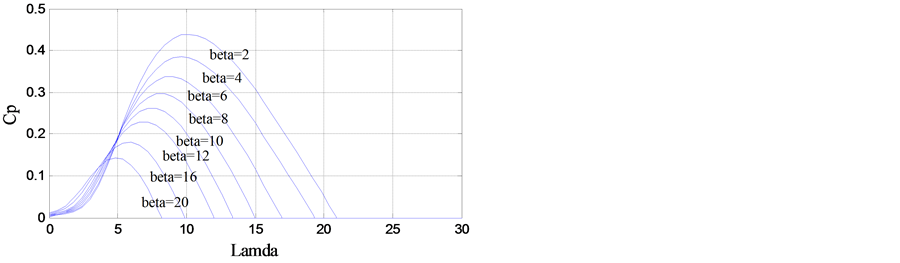
Figure 2. Power coefficient
curve family versus
 and
and .
.
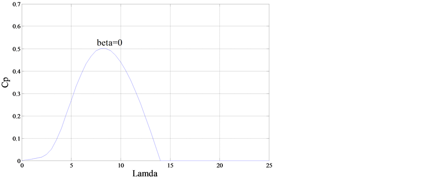
Figure 3. Power coefficient
with different values of
 (with
(with ).
).
To have best results, next simulations are carried with .
.
The aerodynamic torque is determined by [5] :
 (7)
(7)
 (8)
(8)
The aerodynamic turbine power curves family with varying the turbine rotor speed for different value of wind speed illustrated in Figure 4.
With varying the turbine rotor speed for different wind values, the curves family of the aerodynamic torque speed is given by Figure 5.
2.3. Mechanic Model
The fundamental dynamic equation is described with the following equation [2] :
 (9)
(9)
where
 is the electromagnetic torque,
 is the turbine rotor friction.
Then, the wind turbine generator drive that represents the mechanical bloc can be given by:
 (10)
(10)
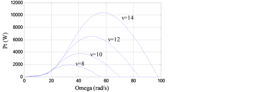
Figure 4. Curve family
of turbine power versus
 and
and .
.
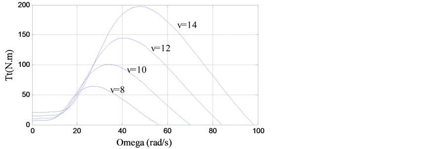
Figure 5. Curve family
of aeodynamic torque versus
 and
and .
.
3. PMSG Model
The PMSG model can be written, in the d-q synchronously rotating reference frame, by the following equation system [1] [6]
 (11)
(11)
where
 are the synchronous rotating reference frame;
 is the armature resistance;
 ,
,
 are the generator inductance on the d-q axis;
 ,
,
 are, respectively, the dand q-axis components
of current;
are, respectively, the dand q-axis components
of current; ,
,
 are the dand q-axis voltage components, respectively,
 is the pole pairs number and
 is the permanent magnet flux.
In the d-q synchronously rotating reference frame, the electromagnetic torque is represented by [1] :
 (12)
(12)
4. Control Strategy
Vector control strategy is used to have more preferment results, to control the wind turbine.
As given in Equation (11) we have a problem of coupling between dand q-axis, represented
by the terms
 and
and . Vector control concept is recommended, in order
to overcome this problem of coupling
. Vector control concept is recommended, in order
to overcome this problem of coupling
4.1. Vector Control Strategy
Vector control strategy is based on the field orientation, . Then according to (12),
since
. Then according to (12),
since
 is constant, the electromagnetic torque is directly proportional to
 [7] .
[7] .
Two inputs
 and
and
 are defined to compensate the cross-coupling terms [1]
[8] ,
are defined to compensate the cross-coupling terms [1]
[8] ,
 (13)
(13)
 (14)
(14)
where
 (15)
(15)
 (16)
(16)
 (17)
(17)
4.2. Current Regulators
According to (16) and (17), two separate first-order models in the d-q axis [8] [9] . Thus,
 (18)
(18)
 (19)
(19)
Therefore, we obtain two similar PI regulators witch used in two independent current loops that one of them controls the q-axis component and the second controls d-component as described in Figure 6.

Figure 6. Control schemes.
4.3. Speed Regulator
Using the mechanical equation of wind turbine (10) the transfer function of the wind speed is written by:
 (20)
(20)
Therefore, based on the last model the wind speed regulator is designed by a PI
controller. Figure 6 illustrates the overall schemes
of the wind turbine control strategy. In fact, the speed controller takes as input
the error between the reference speed
 and the actual rotational speed. Where
 is obtained by
 expression as shown in (4), it can be represented by:
 (21)
(21)
Then, the speed controller output presents
 that is subtracted by the actual
 and the result is the input of the current regulator of the quadrature current component.
The direct component has as input the results of the subtraction between the reference
direct current
and the result is the input of the current regulator of the quadrature current component.
The direct component has as input the results of the subtraction between the reference
direct current
 that it is null in our strategy and the actual one
 . The two controllers have
as outputs the two voltage
. The two controllers have
as outputs the two voltage
 and
and
 that presents the inputs of the decoupling bloc. This later has as outputs the voltage
components
that presents the inputs of the decoupling bloc. This later has as outputs the voltage
components
 and
and
 which present also the outputs of overall control schemes
[8] [10] .
which present also the outputs of overall control schemes
[8] [10] .
5. Simulations Results
Simulations are carried out, in order to prove the wind turbine model and the effectiveness
of the proposed control strategy. The block simulated is represented by Figure 7. It include, the different parts of the Wind Energy
Conversion System [1]
[11] such as the wind turbine model that has as input the electromagnetic
torque
 and the mechanic rotational speed
 as output. The permanent magnet synchronous generator model which has three inputs;
the two voltage components
as output. The permanent magnet synchronous generator model which has three inputs;
the two voltage components
 and
and
 and the electric rotational speed of the wind turbine
 . The control model take
the quadrature current
. The control model take
the quadrature current , the direct current
 and the reference electric wind turbine rotational speed
 as inputs.
The complete WECS bloc given by Figure 7 was built in Simulink and its simulation results are given by Figures 8-19. The wind turbine parameters and the PMSG one used in simulation are illustrated in the Appendix.
Simulations are carried with the following model:
 (22)
(22)
Simulation results demonstrate the performances of the wind turbine model and the
vector control strategy. In fact, the output mechanical rotational speed
 is assumed at the reference one
 ;
;
 is null as desired,
 is proportional to
 . Therefore the value
of the power coefficient can be better than the current one as shown by Figure 19 Cp isn’t the maximum one so the wind turbine power
also isn’t in the max and the tip speed ratio
. Therefore the value
of the power coefficient can be better than the current one as shown by Figure 19 Cp isn’t the maximum one so the wind turbine power
also isn’t in the max and the tip speed ratio
 isn’t optimal as given by Figure 18. The real
 but the optimum one is that illustrated by Figure 19
when Cp is maximum
but the optimum one is that illustrated by Figure 19
when Cp is maximum .
.

Figure 7. Complete model of the wind energy conversion system.
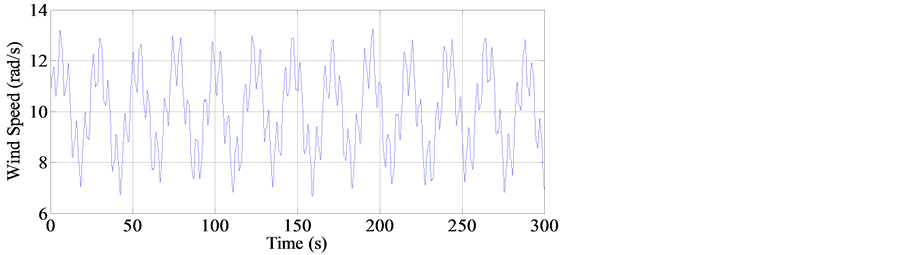
Figure 8. Wind speed profile.
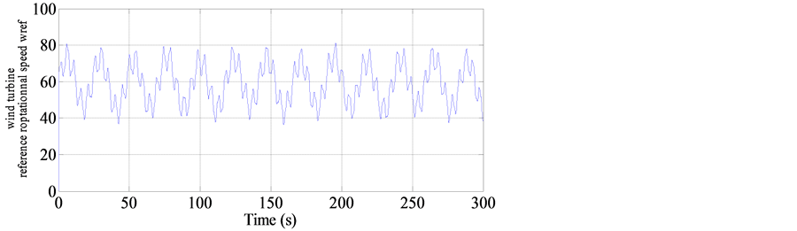
Figure 9. Wind turbine reference rotationnal speed.
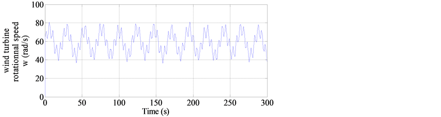
Figure 10. Wind turbine actual rotationnal speed.
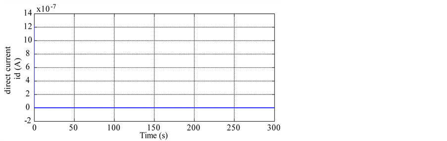
Figure 11. Current component .
.
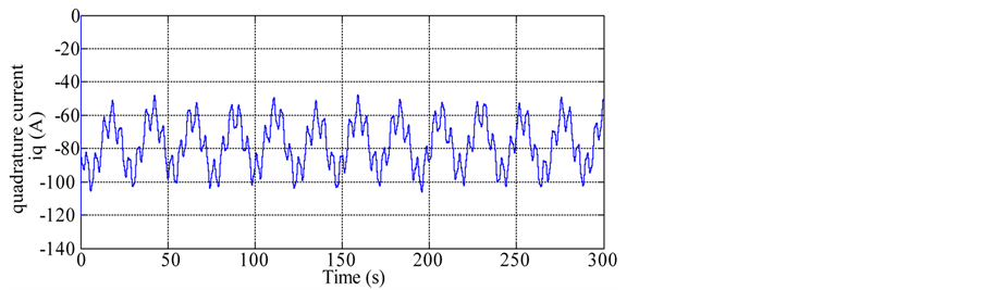
Figure 12. Current component .
.
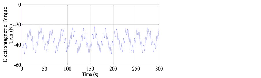
Figure 13. Electromagnetic torque .
.

Figure 14. Voltage component .
.
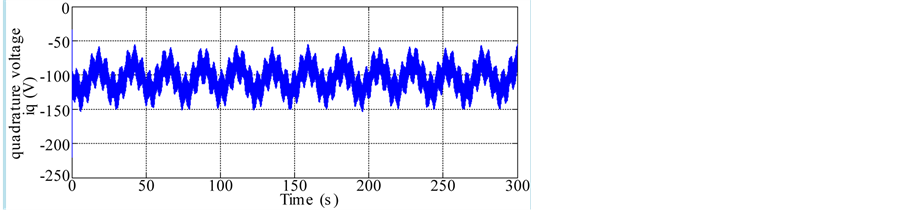
Figure 15. Voltage component .
.
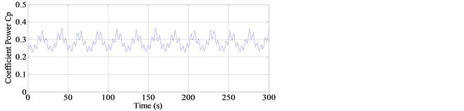
Figure 16. Coefficient power Cp.
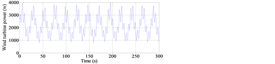
Figure 17. Wind turbine power Pt.

Figure 18. Tip speed
ratio .
.
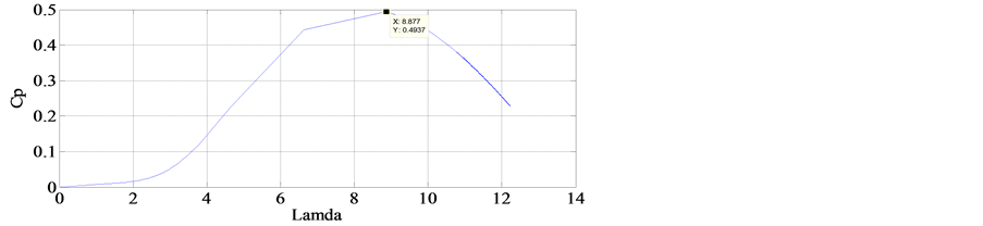
Figure 19. Coefficient power Cp.
6. Conclusion
In this paper, the different bloc of the wind energy conversion system was studied and modeled. In fact, the model of the wind turbine has been presented, the permanent magnet synchronous generator using in variable speed wind turbine has been modeled, controlled and simulated. Using Matlab/Simulink, simulation results were carried when the proposed WECS model was confirmed and the performances of vector control strategy are substantiating.
We faced a number of problems, when making the different component model of the wind energy conversion system. First, the performances of the WECS are relied to the choice of pitch angle. Then, the aerodynamic power is related to the wind speed. And as assumed by simulation results, the coefficient power isn’t in its maximum, the speed ratio isn’t in the optimum one and the turbine power isn’t maximal. So, as results, trying to overcome these problems, we propose for the continuation of this chain of conversion energy controlling the pitch angle, studying and research of the maximum power point tracking to have more preferment results.
[1] Yin, M., Li, G., Zhou, M. and Zhao, C. (2007) Modeling of the Wind Turbine with a Permanent Magnet Synchronous Generator for Integration. IEEE, Power Engineering Society General Meeting, Tampa, 24-28 June 2007, 1-6.
[2] Carranza, O., Figueres, E., Garcera, G. and Gonzalez-Medina, R. (2013) Analysis of the Control Structure of Wind Energy Generation Systems Based on a Permanent Magnet Synchronous Generator. Applied Energy, 103, 522-538. http://dx.doi.org/10.1016/j.apenergy.2012.10.015
[3] Qiu, Z., Zhou, K. and Li, Y. (2011) Modeling and Control of Diode Rectifier Fed PMSG Based Wind Turbine. DRPT: 4th International Conference on Electric Utility Deregulation and Restructuring, and Power Technologies, Weihai, 6-9 July 2011, 1384-1388.
[4] Thongam, J.S., Bouchard, P., Ezzaidi, H. and Ouhrouche, M. (2009) Wind Speed Sensorless Maximum Power Point Traking Control of Variable Speed Wind Energy Conversion System Electric Machines and Drives Conference, Miami, 3-6 May 2009, 1832-1837.
[5] Nath, S. and Rana, S. (2011) The Modeling and Simulation Wind Energy Based Power System Using MATLAB. International Journal of Power System Operation and Energy Management, 1, 12-17.
[6] Chen, X.F., Shu, Z.B. and Zhao, Y.K. (2005) Mathematic Model and Performance Analysis of PMSM, Based Servo System. Journal of Mechanism and Electronics, 1, 1-43.
[7] Sanchez, A.G., Molina, M.G. and Lede, A.M. (2012) Dynamic Model of Wind Energy Conversion Systems with PMSGBased Variable-Speed Wind Turbines for Power System Studies. International Journal of Hydrogen Energy, 37, 10064-10069. http://dx.doi.org/10.1016/j.ijhydene.2011.12.077
[8] Bourourou, F., Louar, F. and Bourass, L. (2013) Simulation of Wind Conversion Chain Model with PI Voltage Regulation. Clearn Electric Power (ICCEP), Alghero, 11-13 June 2013, 707-711.
[9] Abdal Rassul Abbs, F. and Abdulla Abdulsada, M. (2010) Simulation of Wind-Turbine Speed Control by MATLAB. International Journal of Comùputer and Electrical Engineering, 2, 912-915.
[10] El Magri, A., Giri, F., Besançon, G., El fadili, A., Dugard, L. and Chaoui, F.Z. (2013) Sensorless Adaptative Output Feedback Control of Wind Energy Systems with PMS Generators. Control Engineering Practise, 21, 530-543.
[11] Muyeen, S.M., Al-Durra, A. and Tamura, J. (2011) Variable Speed Wind Turbine Generator System with Current Controlled Voltage Source Inverter. Energy Conversion and Management, 52, 2688-2694. http://dx.doi.org/10.1016/j.enconman.2011.02.001
Appendix
