Open Journal of Fluid Dynamics
Vol.07 No.03(2017), Article ID:79060,20 pages
10.4236/ojfd.2017.73020
Numerical Investigation of Particle Rebound Characteristics with Finite Element Method
Mehdi Azimian, Hans-Jörg Bart*
Chair of Separation Science and Technology, Department of Mechanical and Process Engineering, University of Kaiserslautern, Kaiserslautern, Germany

Copyright © 2017 by authors and Scientific Research Publishing Inc.
This work is licensed under the Creative Commons Attribution International License (CC BY 4.0).
http://creativecommons.org/licenses/by/4.0/


Received: August 13, 2017; Accepted: September 11, 2017; Published: September 14, 2017
ABSTRACT
In this work, investigation of particle rebound characteristics due to impact with surface of a target material is presented. The rebound of a spherical particle after impact on a planar surface was analyzed in detail. Specifically, the coefficient of restitution of the particle under various impact conditions was investigated numerically. This study has been conducted by carrying out a series of FEM-based (finite element method) simulations using ANSYS Autodyn software. First, a summary about the state of the art and the theoretical models for the elastic collisions were reviewed. Afterwards, the impact of an aluminum oxide particle on an aluminum alloy target surface was modeled. Using the Autodyn tool, the results were compared and validated by the experimental results of Gorham and Kharaz [1] . Selection of an appropriate equation of state (EOS) and a strength model for each material had a strong effect on the results. For both materials, the Shock EOS was applied for the final simulations. As the strength model, the Johnson-Cook and the elastic model were used, respectively. The agreement of the obtained numerical results with the experimental data confirmed that the proposed model can precisely predict the real behavior of the particle after the impact, when the material models are properly chosen. Furthermore, the effects of impact velocity and impact angle on the rebound characteristics of the particle were analyzed in detail. It was found that the selection of the exact value of friction coefficient has a drastic effect on the prediction of restitution coefficient values, especially the tangential restitution coefficient.
Keywords:
Finite Element Method (FEM), ANSYS Autodyn, Single Particle Impact, Restitution Coefficient, Friction Coefficient

1. Introduction
The coefficient of restitution of a particle impacting a target surface is the ratio of the particle velocities after and before the impact. This positive real number varies from 0.0 to 1.0 depending on the characteristics of the materials used and the impact conditions. The coefficient of restitution e, for a normal impact as depicted in Figure 1 is defined with the following relation:
(1)
where Vr is the rebound velocity and Vi is the impact velocity. During normal impacts, where no tangential component is included between the particle and the target surface, there are two ways of losing energy. One way is due to the dissipation of the stress wave propagation and the other one due to the plastic deformation. In the case of a colliding sphere, three different kinds of deformation can be identified; elastic, elastic-plastic and fully plastic. An elastic shock takes place at the beginning of the collision. When the stress is large enough, plastic deformation begins to occur in the area of the contact point. This deformation depends mainly on the impact velocity and on the material properties of both the materials involved, i.e. the particle and target. When the maximum compression is achieved, an amount of elastic energy is stored. At this moment, the contact force starts to decrease by releasing some of the energy back to the sphere and promoting the rebound of the particle. This restitution phase can be considered as elastic because only elastic strain energy is released. If an impact is perfectly elastic, energy is dissipated by the propagation of elastic waves. Hunter (1957) [2] showed theoretically that this was less than 1% of the initial kinetic energy for the impact of a steel ball on a large block of steel or glass. Dahneke (1971) [3] calculated that the coefficient of restitution of elastic collisions was in the range 98% - 99%, implying that the energy loss by elastic waves is less than 1% or 2% of the total impact energy.
2. Theoretical Models
When analysing elastic impacts, the behaviour of such collisions can be introduced theoretically using Hertz theory (1881) through a quasi-static procedure

Figure 1. A normal impact of a particle on a surface.
[4] . When the yield stress is reached, one of the two colliding bodies starts its plastic deformation. Several investigations and researches had taken place during last decades but it has been hard to find a general solution that fits to the experimental results. One of the first equations for predicting the restitution coefficient e, was proposed by Chang (1992) [5] that used a model realised by Chang et al. (1987) [6] . Few years later, Stronge (1995) [7] proposed an equation for predicting the coefficient of restitution as given here with Equation (2):
(2)
where Vy is the yield point velocity. For Vi = Vy, e = 1.
For , the Equation (2) simplifies to:
(3)
However, Stronge’s Equation (2) predicts e > 1 for , which is an impossible condition. Thornton (1997) [8] derived a new equation for the coefficient of restitution (Equation (4)). He studied the collision of two spheres with each other. The process was divided into four parts: the elastic loading, the yield strength, the plastic loading and the elastic unloading. The equation was proposed by dividing the problem into a perfectly elastic portion and perfectly plastic portion.
(4)
It satisfies the condition e = 1.0 when Vi = Vy. At high velocities, (Vy/Vi)2 → 0 and Equation (4) becomes:
(5)
And finally if , the following relation for coefficient e is obtained:
(6)
In the case analysed in Thornton’s work [8] , a sphere impacts a plane surface. For this particular case the yield velocity Vy, is defined as:
(7)
For this particular case, by substituting Equation (7) into Equation (6), the following expression is obtained:
(8)
Later, Vu-Quo and Zhang (1999) [9] proposed a model of elasto-plastic normal force displacement (NFD). The key feature of this model is the additive decomposition of the radius of the contact area into an elastic part and a plastic part. Li et al. (2001) [10] presented a model which can be considered as an evolution of what was done in [11] . In this model, the authors used a more detailed pressure distribution function that was based on the FEM results. The model presented a better fit for the lower velocities. Gorham and Kharaz (2000) [1] provided experimental data on various impact situations to provide quantitative support for theoretical models of the collision process. The study is based on the impact of the 5 mm aluminium oxide spherical particles on flat plates. The plates were made of either mild steel if the elastic case is to be analysed, or of aluminium alloy in the case of a plastic impact. Weir and Tallon (2005) [12] examined the theoretical regimes that take part in a normal low velocity impact. They reviewed and extended the theory of the coefficient of restitution including the effect of variable particle size. They [12] have theoretically noted that the coefficient of restitution for equally sized sphere-sphere contact is about 19% smaller than for sphere-plate contact. This statement was also proven experimentally. It was also demonstrated that for repeated collisions between two spheres at the same point, the restitution coefficient increases and approaches to one, becoming an elastic collision.
Jackson and Green (2010) [13] presented a different methodology for modeling the impact phenomena between elasto-plastic spheres. Recent FEM results modeling the static deformation of an elasto-plastic sphere were used in conjunction with equations for the variation of kinetic energy to obtain predictions for the coefficient of restitution. The model predicts that a specific amount of energy will be dissipated in the form of plastic deformation such that as the initial impact velocity increases, the coefficient of restitution decreases. The work also derived a new equation for the initial critical velocity, which causes initial plastic deformation in the sphere. This is different than the one shown in previously derived equations and is strongly dependant on Poisson’s ratio. The work also compared the prediction between several models that make different predictions and the results were compared with the experimental data. Moreover, the different phases of the shock were well explained based on previous works. A new critical velocity was determined as a function of the critical interference ωc. Furthermore, the effects of varying material and geometrical properties like the yield strength, elastic modulus, Poisson’s ratio and sphere radius were investigated [13] . The model proposed by Chang and Ling [5] predicts that the contact becomes fully plastic immediately just after the contact, while the model proposed by Jackson [13] includes a smoother transition from elastic to elastic-plastic and eventually fully plastic deformation.
3. Finite Element Method (FEM) Analysis
The FEM should be understood as a method for finding an approximate solution for a simplified model. Numerical treatment reduces the simplified model to a form which is solvable by a finite number of numerical operations. This means that the approximate solution has to be characterized by a finite number of parameters, called degrees of freedom. One of the earliest work in the field of particle impact that used a finite element software was the work done by Lim and Strong (1998) [14] . In their work, the energy dissipation during an impact between hard cylindrical bodies with parallel axes was analysed. An energy analysis was realised in every step of the colliding process and it was verified with DYNA2D simulations. In the FEM simulation, the cylinder made of steel was modelled as a rigid body while the aluminium alloy symmetric half-geometry was modelled as behaving in a linearly elastic-perfectly plastic manner. Lim and Stronge [14] based their conclusions on the loss of energy. When no deformation occurs, the energy loss is based on the elastic waves. However, when some plasticity appears, the losses due to the elastic waves become so small that can be neglected. Furthermore, they concluded that it is important to take into account whether the deformation field is two or three dimensional in order to obtain an accurate prediction for the coefficient of restitution as a function of normal impact velocity.
Vu-Quo and Zhang [9] studied two identical spheres in contact and subjected only to a normal force. This case, due to symmetry, turned into a single sphere contacting a frictionless rigid surface. The mesh had 2141 axisymmetric six-nodes triangular elements. The sphere had a radius of 0.1 m with properties of an aluminium alloy. Li et al. (2000) [15] conducted a numerical study of the normal impact of elasto-plastic spheres with a rigid wall by employing DYNA2D simulation tool. Results regarding the deformation, time evolution of the contact force and contact force-displacement relationships during the impact were presented. Li et al. [15] presented the influence of the material behaviour by analysing three different cases: an elastic material, an elasto-plastic material and finally an elastic-perfectly plastic material. The analysed sphere had a diameter of 20 µm and the mesh was consisted of 1250 four-nodes elements. They [15] compared the coefficient of restitution obtained in their FEM analysis with the models previously presented by Johnson [11] and by Thornton [8] .
Zhang and Vu-Quo (2001) [16] discussed the modeling of the coefficient of restitution as a function of the impact velocity and compared the results from the nonlinear finite analysis, studied with two recent normal force displacement models; One created by Thornton [8] and the other one modelled by themselves in an earlier work [9] . The relationship among the coefficient of restitution, impact velocity, collision time, contact force and the normal pressure distribution were presented and discussed. The nonlinear FEM code ABAQUS was used. Three various meshes having six-node triangular elements were generated to see how it influences the output results. In the study of the elastic part, there was a close agreement between the simulations and the Hertz theory. When analysing the elasto-plastic case, they compared the simulations carried out with their three various cases and the models proposed earlier [7] [8] [9] .
Wu et al. [17] presented the finite element analysis of the impact of a sphere with a surface using DYNA2D. Because of geometrical and loading symmetries, only half part of the geometries were considered and simulated. For each case, they considered a wide range of impact velocities, at which the deformation behaviour ranges from elastic to significant plastic deformation. The influence of the substrate was also evaluated by changing its size. When the size is varied, there is the possibility that the restitution coefficient varies due to stress waves. However, in their work, it can be seen that the coefficients of restitution obtained by varying the size of the substrate are close and the maximum relative deviation is only about 2% in relatively high initial velocities. They presented the equations of the restitution coefficient for the impacts of an elastic sphere with an elastic-perfectly plastic symmetric half-space:
(9)
where E* is the normalized elastic modulus and Y is the yield stress. And for the impacts of an elastic-perfectly plastic sphere with a rigid wall:
(10)
The onset of finite plastic-deformation impact has been determined in terms of Vi/Vy and E*/Y for different impact configurations. The FEM results showed that for the impact of small deformation, the coefficient of restitution is mainly dependant on Vi/Vy, which is consistent with those predicted by the theory of impact mechanics. While for the impact of finite plastic deformation, the restitution coefficient is also dependent on E*/Y. The conclusion of their work was that when finite plastic deformation occurs, the restitution coefficient is proportional to .
In another work, Thornton et al. [18] presented the results of a finite element analysis of elastic and elasto-plastic oblique impacts of a sphere with a wall using the finite element analysis code DYNA3D. A 3-D finite element model was used. Because of the geometrical symmetry, again only the half-space of the model was simulated. Three different impact cases for the oblique impact were investigated. The sphere was treated as rigid and as an elastic-perfectly plastic body, while the target surface was analysed as elastic, elastic-perfectly plastic and as a rigid body. The impact was modelled by applying an initial velocity to every node of the sphere. The impact angle was varied from 0˚ (normal impact) to 85˚ (close to glancing). After the impact, the normal restitution coefficient ( ) and the tangential restitution coefficient ( ) were analysed. Due to the friction between the sphere and the symmetric half-space, an angular velocity component was appeared in the sphere after impact. The following relation was determined for the tangential restitution coefficient:
(11)
where is the Coulomb coefficient of friction and is the particle impact angle.
Thornton et al. [18] demonstrated that in oblique impacts, the normal coefficient of restitution does not depend on the normal impact velocity only, but also depends on the impact angle. Jackson and Green (2005) [19] presented the FEM study of elasto-plastic hemispherical contact. The numerical results were compared to other existing models of spherical contact truncation model, often attributed to Abbot and Firestone (1933) [20] , and the perfect elastic case known as the Hertz contact [4] [21] . ANSYS software was applied, however the results were confirmed by using ABAQUS. An axisymmetric 2-D model was used and yield point occurred according to the von Mises criterion. The generated mesh consisted of at least 11,101 four-node elements. It was theoretically demonstrated that the fully plastic average contact pressure is not always at the same point. This point varies when the geometry is deformed. Therefore, it is dependent on material properties. Large differences between the approximated analytical models and other numerical solutions were revealed. It was found that the contact area, force and the pressure are dependent on the deformed geometry and also dependent on the material properties in both cases, the elasto-plastic and the plastic regime.
In this work, investigation of particle rebound characteristics due to impact with surface of a target material is presented. The rebound of a spherical particle after impact on a planar surface was analyzed in detail. Specifically, the coefficient of restitution of the particle under various impact conditions was investigated numerically. This study has been conducted by carrying out a series of finite element method (FEM) based simulations using ANSYS Autodyn software.
4. Experimental Details
Experimental measurement of the rebound particle characteristics with an extremely good precision is a time-consuming process. However, this is necessary for validation of numerical results. In this part of the work, the measurement technique used in works of Gorham and Kharaz [1] [22] is explained briefly. In their experiments, spherical particles of 5 mm diameter were fallen under gravity on an inclined anvil. A high-speed camera with strobe illumination was used to form a sequence of images on a single frame. Aluminium oxide spheres impacting on a thick soda-lime glass anvil (which showed a fully elastic response) and to an aluminium alloy anvil (with some plastic deformation involved) were considered. The measurements by the digital high-speed camera were analysed by an image processing software. The velocities and angles of impact and rebound and the rotation after the impact were given as the output of these measurements. Finally, the normal and tangential coefficients of restitution were calculated. To obtain accurate results, it is necessary to ensure that the impacts are reproducible and the measurements are precise. For achieving this, critical attention was made for the mechanical design, construction, calibration, image-forming optics, direction and uniformity of illumination, precise electronic control, reproducible surfaces, accuracy of the particles and the computer-based measurement procedures. Because of this, the final system has produced measurements of particle rotation, normal restitution coefficient within 1˚ of glancing incidence, and tangential restitution coefficient to within 1˚ of normal impact with a very high accuracy and reproducibility. This has allowed reliable and quantitative data to be obtained considering the effects of material properties and surface conditions on rebound parameters. The main objective of the system used by Kharaz (1999) [23] was to record a sequence of images of a particle impacting on an inclined anvil in a single frame. Before the impact, the particle is held at a desired height by a vacuum nozzle. Depending on the velocity required for the impact, the particle is dropped from different heights. When particle is released, it falls through an optical-fibre triggering device. An electronic system then generates a sequence of pulses to control the camera and the strobe light, to take a single frame of images in a pre-defined manner. Materials properties used in the experimental work are presented in Table 1 and applied for the simulations in the current study as well.

Table 1. Material properties of the particle and target surface.
5. Modeling
The geometries of the 5 mm spherical particle and the anvil with a size of 140 × 125 × 25 mm were generated. In the studied case, the longitudinal wave speed in the target material is around 5.3 km/s [1] . Giving a double transit to the 25 mm thick anvil, the propagation wave is back to the impact point in approximately 9.4 µs, which is smaller than the contact time between the sphere and the surface. Although the longer contact time means in principle that stress waves generated at the start of the impact can return and influence the rebound characteristics, this effect is very small. Moreover, the effect of the wave propagation in the coefficient of restitution when some plasticity takes place is neglected. The geometry was created with “Design modeller” tool. This geometry modeling tool is provided by ANSYS. Three bodies have been created. The first body is the colliding spherical particle. This body has a diameter of 5 mm and consequently a weight of 0.255 grams. The second body is the target body. The third body is located inside the target under the surface where the collision takes place. As boundary condition, no movement was allowed at the faces of the surface. Once the bodies were created and the boundary conditions were applied, a symmetry plane was created in order to reduce the computational time.
1) Equation of State (EOS)
The hydrodynamic response of a material is described by the equation of state. This is the primary response for gases and liquids, which can withstand no shear. Their response to dynamic loading is assumed to be hydrodynamic, with pressure varying as a function of internal energy and density. However, for the solid phase, this is also the primary response at high deformation rates, when the hydrodynamic pressure is far greater than the yield stress of the solid material [24] . For the current study, the Shock EOS was applied for both the particle and target material as the final selected EOS. The Shock EOS linear model is based on the Rankine-Hugoniot equations [25] for the shock jump conditions. It defines a relation among the variables ρ (density), p (pressure), e (energy), up (particle velocity) and U (shock propagation velocity). The choice of this equation of state has been proved in other studies (e.g. by Corbett [26] ) and is widely used as the correct representation of material behavior for most metals. In many dynamic experiments, it was found that for most solids and liquids under shock-like action of an impact, the following relationship exists:
(12)
where s is the linear Hugoniot slope coefficient and c0 is the sound speed in the material. This equation of state is specified in the Mie and Gruneisen form [27] as the following equation:
(13)
where it is assumed that is constant and the pressure and energy terms are defined as Equation (14) and Equation (15), respectively.
(14)
(15)
where is the Gruneisen parameter, , ρ is the current density and ρ0 is the initial density. The equation of state in this form is only valid for a limited impact velocity range, because it does not include a phase change, such as melting or vaporization.
2) Material Strength Model
Solid materials may initially respond elastically, but under highly dynamic loadings, they can reach stress states that exceed their yield stress and deform plastically. Material strength laws describe this nonlinear elastic-plastic response. In this study, Johnson-Cook strength model [28] was applied as the final model for the target material having a ductile behavior. This model can be represented in the following form:
(16)
where σ is the flow stress, σ0 is the yield strength, ε is the equivalent plastic strain, is the normalized plastic strain rate and T* is the normalized temperature based on a reference melt temperature. The five material parameters are σ0, B, C, n and m. The expression in the first bracket is the stress as a function of elongation when and T* = 0. The constants B and n represent the effect of cold deformation. The expression in the second bracket represents the effect that the elongation rate has on the yield strength of the material. The last term represents the thermal softening so that the yield strength approaches zero when the melting temperature is reached. The constant m represents the thermal softening exponent.
5.1. Normal Impacts
As it is explained in the state of the art, the experimental data of Gorham and Kharaz [1] , which presented the rebound characteristics of the aluminium oxide spherical particles colliding an aluminium alloy anvil, was used to validate the numerical results of the current study. In the experiments, the two parameters that varied were the particle velocity by varying the height, and the colliding angle between the sphere and the target surface by adjusting the anvil orientation angle. Applying the ANSYS Workbench 14.5 and ANSYS Autodyn, the main objectives were the reproduction of the experiments, performing detailed parameter analysis and investigation of appropriate models for describing the hydrodynamics and material strength behaviour of both the particle and target. In the first step of simulations that were run, the Shock EOS was selected for the particle and the Von Mises model was applied as the strength model. For the target material, the Shock EOS was applied here as well, however no strength model was selected for the target. In simulation step 2 compared to simulation step 1, only the mesh was modified by varying the number of elements of the geometry. In Table 2, the material properties used in simulation steps 1 and 2 are presented.
As it can be observed in Figure 2, the coefficient of restitution remained constant for the different impact velocities. First modification after simulation step 1, was to increase the number of elements by modifying element size of the mesh using Explicit Dynamics Modeller. The first step simulation was analysed with 7318 elements, while the geometry for the second simulation had 112,712 elements. The restitution coefficient value predicted with the simulation step 2 was smaller in comparison with simulation step 1 but remained also constant by variation of the impact velocity. The next step was to apply appropriate material models for the colliding particle and the target material. Table 3 presents the characteristics of the simulation steps 3 and 4. The Polynomial EOS and Johnson-Holmquist strength model were applied for the particle and the Shock EOS and Johnson-Cook strength model for the target.
As it can be observed in Figure 3, the coefficient of restitution derived from the simulation step 3 tends to decrease as the impact velocity increases. This simulation involves a bigger plastic deformation of particle in contact with the anvil. It is important to mention that although the obtained results do not fit much good to the experimental results, the change of the results tendency was an important step in evaluating the simulation results. After observing that the results have changed when applying the strength model due to the plasticity of
Table 2. Material, EOS and strength model used in simulation steps 1 and 2.
Table 3. Material, EOS and strength model used for simulation steps 3 and 4.

Figure 2. Simulation steps 1 and 2 compared with the experimental data of Gorham and Kharaz [1] .

Figure 3. Simulation step 3 compared with the experimental data of Gorham and Kharaz [1] .
the material, the next step was to modify the mesh with a better precision. A third body has been created inside the big anvil. This body has been located exactly where the impact takes place as shown in Figure 4.
Table 4 presents the characteristics of the simulation steps 5 and 6. As it can be observed in Figure 5, the results from simulation step 5 are quite similar to the results of simulation step 4. Both simulation steps 4 and 5 have the same mesh but with different models described already in Table 2 and Table 3. The first objective was to find and implement the appropriate equation of state and strength models in order to define the behaviour of materials and to reach the similar trend as the experimental results. Once the trend has been found, the next step is the grid-independence study. The grid-independence study was carried out to provide the best relation between the results of the restitution coefficient and the computational effort. With an initial impact velocity of 2 m/s, an impact angle of 90˚ (normal impact) and the material models already mentioned,
Table 4. Material, EOS and strength model used for simulation steps 5 and 6.

Figure 4. Modified mesh by locating a finer mesh at the impact area.

Figure 5. Simulation steps 4, 5 and 6 compared with the experimental data of Gorham and Kharaz [1] .
different meshes were studied. The sphere and the part of the surface where the collision takes place were meshed with an equal element size. In the other part of the surface, where the stress is negligible, the element size can be generated coarser. The mesh has been refined step by step. The number of elements was increased by decreasing the element size.
In Table 5, the refinement procedure is shown. The variation of the coefficient of restitution is observed for eight different grids with identical boundary conditions. The aim of the grid independence study is to select the best grid that provides reliable results combined with an acceptable computational time. Due to the small deviation of results between grids 7 and 8, the grid 7 with 475,401 elements was chosen as the final mesh. In Figure 6, mesh number 7 selected as the final mesh is shown as a focused view to observe the fineness of the particle’s mesh and the impact area’s mesh. In Figure 7, the evolution of the coefficient of restitution as a function of the number of elements is presented. When the mesh has less than 100.000 elements, the coefficient does not go under any variation and remains constant at 1.
Table 5. Restitution coefficient and deviation for different grids.
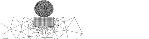
Figure 6. Mesh number 7 selected as the final mesh.

Figure 7. Restitution coefficient as the grid independence study criterion.
In Figure 5, the simulation step 6 represents the results using the mesh number 7. The results obtained have also been compared to several theoretical models. In Figure 8, the simulation results obtained by the Autodyn software are compared with the experimental results of Gorham and Kharaz [1] and with the theoretical models of Thornton [8] and Wu et al. [17] .
5.2. Oblique Impacts
In the previous part of the work, all the simulations that have been presented were collision cases with only a normal velocity component. In this part, several simulations with also a tangential component of impact were performed. Figure 9 shows the oblique impact and rebound of a spherical particle on a target surface.
Gorham and Kharaz [1] fixed the particle drop height so that the impact velocity of particle was fixed at 3.85 m/s. By varying the inclination of the anvil,

Figure 8. Comparison of experimental data [1] with simulation and theoretical results.
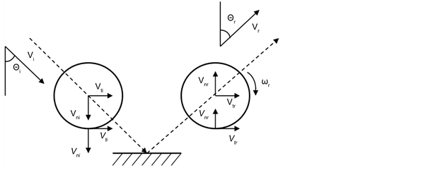
Figure 9. Oblique impact parameters.
they covered a collision angle ranging from 5˚ to 88˚. In the following diagrams, the obtained simulation results are validated with the experimental data of Gorham and Kharaz [1] . In Figure 10, it can be observed that the experimental data and simulation results are in a very good agreement, confirming that the created model reproduces the behaviour of the experimental values of the normal restitution coefficient with a great precision. The results show that as the impact angle increases, the normal coefficient of restitution decreases asymptotically. The results are logical because the normal component of the velocity is bigger for the bigger impact angles. Figure 11 presents a comparison of the experimental data and the simulated values for the tangential restitution coefficient as a function of impact angle. As it is observed, by an increase of the impact angle from 0˚ to 90˚, the tangential restitution coefficient decreases almost linearly and reaches a minimum value (in this case at 60˚) and increases gradually again

Figure 10. Normal restitution coefficient as a function of impact angle.

Figure 11. Tangential restitution coefficient as a function of impact angle.
when the impact angle approaches 90˚.
Although the trends of the experimental data and simulation values are similar in Figure 11, the obtained simulation results do not fit precisely to the experimental data of Gorham and Kharaz [1] . The maximum difference between experimental and simulation results, occurs at about impact angle of 45˚, where the deviation is almost 16%. After analysing this deviation, it was found that the difference between the two curves originates from the friction coefficient µ. As presented by Gorham and Kharaz [1] , the tangential restitution coefficient depends on the normal restitution coefficient en, on the impact angle θi, and on the friction coefficient µ, based on Equation (11).
In Figure 12, the theoretical tangential restitution coefficient for the cases of µ = 0.1, µ = 0.18 and µ = 0.25 are added to the curves in Figure 11. As depicted, it was found that the friction coefficient has to be modified and set based on the particle and target materials. The selected friction coefficient was 0.1 for previous simulations, while the correct value has to be selected as µ = 0.18. This error in selection of friction coefficient did not have any influence on the results of the normal restitution coefficient. On the other hand, as it can be observed in Figure 12, the variation of the friction coefficient has a considerable influence on the tangential coefficient of restitution and therefore on the rebound velocity and rebound angle.
6. Conclusions
The challenge to find a theoretical model to predict the rebound behaviour of a particle when some plastic deformation takes place was observed. During the past decades, several theoretical models have been presented that tried to predict the rebound of the particle. However, the theoretical models predict the trend qualitatively good but not quantitatively well. In the present study, the analysed
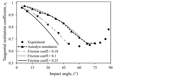
Figure 12. Influence of the friction coefficient on the tangential restitution coefficient.
impact velocities were between 0.5 and 7 m/s and plasticity started in the aluminium alloy surface from the impact velocity of about 0.7 m/s. Therefore, almost the whole investigation occurred in an elasto-plastic regime.
Despite the difficulty of predicting the restitution coefficient for collisions with plastic deformation, by applying the finite element method, ANSYS Autodyn tool, the obtained results had a good agreement with the experimental values [1] for the aluminium oxide sphere colliding to a flat surface. The influences of affecting parameters such as the impact velocity and the impact angle on the restitution coefficient behaviour were investigated in detail. According to our results, when the impact angle was fixed and the velocity increased, et did not suffer big variations, however en decreased notably. By an increase of the impact angle from 0˚ to 90˚, the tangential restitution coefficient decreases almost linearly and reaches a minimum value and increases gradually again when the impact angle approaches closer to the 90˚. The normal restitution coefficient decreased asymptotically by an increase of the impact angle.
During the evaluation of the work, it has been observed that the final mesh chosen for the simulations had a big importance to accurately predict the impact. Furthermore, in the present study, the shock equation of state provided better results and was used for both aluminium oxide and aluminium alloy 2024. The strength model that provided the best response was the Johnson-Cook model for the target, and the elastic model for the impacting spherical particle. Selection of the correct friction coefficient had an important influence on the precise prediction of tangential coefficient of restitution and therefore on the rebound velocity and rebound angle of the particle.
Acknowledgements
The authors would like to thank “Stiftung Rheinland-Pfalz für Innovation, Mainz, Germany” for financial support.
Cite this paper
Azimian, M. and Bart, H.-J. (2017) Numerical Investigation of Particle Rebound Characteristics with Finite Element Method. Open Journal of Fluid Dynamics, 7, 310-329. https://doi.org/10.4236/ojfd.2017.73020
References
- 1. Gorham, D. and Kharaz, A. (2000) The Measurement of Particle Rebound Characteristics. Powder Technology, 112, 193-202. https://doi.org/10.1016/S0032-5910(00)00293-X
- 2. Hunter, S. (1957) Energy Absorbed by Elastic Waves during Impact. Journal of the Mechanics and Physics of Solids, 5, 162-171. https://doi.org/10.1016/0022-5096(57)90002-9
- 3. Dahneke, B. (1971) The Capture of Aerosol Particles by Surfaces. Journal of Colloid and Interface Science, 37, 342-353. https://doi.org/10.1016/0021-9797(71)90302-X
- 4. Hertz, H. (1881) über die Berührung fester elastischer Körper. [Collisions of Solid Elastic Bodies.] Journal für die reine und angewandte Mathematik, 92, 156-171.
- 5. Chang, W.-R. and Ling, F.F. (1992) Normal Impact Model of Rough Surfaces. Journal of Tribology, 114, 439. https://doi.org/10.1115/1.2920903
- 6. Chang, W.-R., Etsion, I. and Bogy, D.B. (1987) An Elastic-Plastic Model for the Contact of Rough Surfaces. Journal of Tribology, 109, 257-263. https://doi.org/10.1115/1.3261348
- 7. Stronge, W. (1995) Coupling of Friction and Internal Dissipation in Planar Collisions of Copliant Bodies. Contact Mechanics, 417-426. https://doi.org/10.1007/978-1-4615-1983-6_57
- 8. Thornton, C. (1997) Coefficient of Restitution for Collinear Collisions of Elastic-Perfectly Plastic Spheres. Journal of Applied Mechanics, 64, 383-386. https://doi.org/10.1115/1.2787319
- 9. Vu-Quoc, L. and Zhang, X. (1999) An Elastoplastic Contact Force-Displacement Model in the Normal Direction: Displacement-Driven Version. Proceedings of the Royal Society of London A, 455, 4013-4044. https://doi.org/10.1098/rspa.1999.0488
- 10. Li, L.-Y., Wu, C.-Y. and Thornton, C. (2001) A Theoretical Model for the Contact of Elastoplastic Bodies. Mechanical Engineering Science, 216, 421-431. https://doi.org/10.1243/0954406021525214
- 11. Johnson, K.L. (1987) Contact Mechanics. Cambridge University Press, Cambridge [Cambridgeshire], New York.
- 12. Weir, G. and Tallon, S. (2005) The Coefficient of Restitution for Normal Incident, Low Velocity Particle Impacts. Chemical Engineering Science, 60, 3637-3647. https://doi.org/10.1016/j.ces.2005.01.040
- 13. Jackson, R., Green, I. and Marghitu, D. (2010) Predicting the Coefficient of Restitution of Impacting Elastic-Perfectly Plastic Spheres. Nonlinear Dynamics, 60, 217-229. https://doi.org/10.1007/s11071-009-9591-z
- 14. Lim, C. and Stronge, W. (1998) Normal Elastic-Plastic Impact in Plane Strain. Mathematical and Computer Modelling, 28, 323-340. https://doi.org/10.1016/S0895-7177(98)00125-3
- 15. Li, L.Y., Thornton, C. and Wu, C.Y. (2000) Impact Behaviour of Elastoplastic Spheres with a Rigid Wall. Proceedings of the Institution of Mechanical Engineers, 214, 1107-1114. https://doi.org/10.1243/0954406001523551
- 16. Zhang, X. and Vu-Quoc, L. (2002) Modeling the Dependence of the Coefficient of Restitution on the Impact Velocity in Elasto-Plastic Collisions. International Journal of Impact Engineering, 27, 317-341. https://doi.org/10.1016/S0734-743X(01)00052-5
- 17. Wu, C.-Y., Li, L.-Y. and Thornton, C. (2003) Rebound Behaviour of Spheres for Plastic Impacts. International Journal of Impact Engineering, 28, 929-946. https://doi.org/10.1016/S0734-743X(03)00014-9
- 18. Wu, C.-Y., Thornton, C. and Li, L.-Y. (2003) Coefficients of Restitution for Elastoplastic Oblique Impacts. Advanced Powder Technology, 14, 435-448. https://doi.org/10.1163/156855203769710663
- 19. Jackson, R. and Green, I. (2005) A Finite Element Study of Elasto-Plastic Hemispherical Contact against a Rigid Flat. Journal of Tribology, 127, 343-354. https://doi.org/10.1115/1.1866166
- 20. Abbott, E.J. and Firestone, F.A. (1933) Specifying Surface Quality—A Method on Accurate Measurement and Comparison. Mechanical Engineering ASME, 55, 569-572.
- 21. Timoshenko, S. and Goodier, J.N. (1951) Theory of Elasticity. McGraw-Hill, New York.
- 22. Kharaz, A., Gorham, D. and Salman, A. (2001) An Experimental Study of the Elastic Rebound of Spheres. Powder Technology, 120, 281-291. https://doi.org/10.1016/S0032-5910(01)00283-2
- 23. Kharaz, A., Gorham, D. and Salman, A. (1999) Accurate Measurement of Particle Impact Parameters. Measurement Science and Technology, 10, 31-35. https://doi.org/10.1088/0957-0233/10/1/009
- 24. ANSYS Mechanical User Guide Release 14.5 (2012).
- 25. Needham, C. (2010) The Rankine-Hugoniot Relations. In: Blast Waves, Springer Berlin Heidelberg, 9-15. https://doi.org/10.1007/978-3-642-05288-0_3
- 26. Corbett, B. (2006) Numerical Simulations of Target Hole Diameters for Hypervelocity Impacts into Elevated and Room Temperature Bumpers. International Journal of Impact Engineering, 33, 431-440. https://doi.org/10.1016/j.ijimpeng.2006.09.086
- 27. Holzapfel, W.B. (1998) Equations of State for Solids under Strong Compression. High Pressure Research, 16, 81-126. https://doi.org/10.1080/08957959808200283
- 28. Johnson, G.R. and Cook, W.H. (1983) A Constitutive Model and Data for Metals Subjected to Large Strains, High Strain Rates and High Temperatures. Proceedings: Seventh International Symposium on Ballistics, Hague, 19-21 April 1983, 654.
- 29. Mises, R.V. (1913) Mechanik der festen Körper im plastisch-deformablen Zustand. [Mechanics of Solid Bodies in Plastic Deformation State.] Nachrichten von der Gesellschaft der Wissenschaften zu Gottingen (Mathematisch-physikalische Klasse), 1, 582-592.
- 30. Holmquist, T.J. and Johnson, G.R. (1991) Determination of Constitutive Model Constants from Cylinder Impact Tests. Journal of Physics E: Scientific Instruments, 1, C3-853-C3-860.