Open Journal of Fluid Dynamics
Vol.3 No.4(2013), Article ID:40403,5 pages DOI:10.4236/ojfd.2013.34032
Study on the Wake Shape behind a Wing in Ground Effect Using an Unsteady Discrete Vortex Panel Method
1Department of Aeronautical and Mechanical Design, Korea National University of Transportation, Chungju, Republic of Korea
2Department of Civil, Architectural and Environmental Engineering, University of Texas at Austin, Austin, USA
Email: *chhan@ut.ac.kr
Copyright © 2013 Cheolheui Han, Spyros A. Kinnas. This is an open access article distributed under the Creative Commons Attribution License, which permits unrestricted use, distribution, and reproduction in any medium, provided the original work is properly cited.
Received August 13, 2013; revised September 13, 2013; accepted September 20, 2013
Keywords: Wake Shape; Wing in Ground Effect; Unsteady Discrete Vortex Method
ABSTRACT
The unsteady evolution of trailing vortex sheets behind a wing in ground effect is simulated using an unsteady discrete vortex panel method. The ground effect is included by image method. The present method is validated by comparing the simulated wake roll-up shapes to published numerical results. When a wing is flying in a very close proximity to the ground, the optimal wing loading is parabolic rather than elliptic. Thus, a theoretical model of wing load distributions is suggested, and unsteady vortex evolutions behind lifting lines with both elliptic and parabolic load distributions are simulated for several ground heights. For a lifting line with elliptic and parabolic loading, the ground has the effect of moving the wingtip vortices laterally outward and suppressing the development of the vortex. When the wing is in a very close proximity to the ground, the types of wing load distributions does not affect much on the overall wake shapes, but parabolic load distributions make the wingtip vortices move more laterally outward than the elliptic load distributions.
1. Introduction
When a wing is flying near the ground, the aerodynamic characteristics of the wing is changed due to the interaction of the wing and the ground. This phenomenon is called as wing-in-ground (WIG) effect. New conceptual vehicles utilizing the WIG effect has been suggested focusing on fuel efficiency and stability [1].
Panel methods have been frequently applied to the conceptual design of wing-in-ground effect vehicles [2]. Many free-wake analysis techniques have been developed in order to represent the complicated wake vortex behavior behind a wing (Hoeijmakers and Vaatstra [3], Ribeiro and Kroo [4], Zhu and Takami [5], for example). Lamarre and Paraschivoiu [6] showed that the large-scale behavior of the roll-up of the aircraft trailing vortices can be simulated using the shape of 2-dimensional vortex sheet at any pseudo time because it resembles the shape of the cross section of the 3-dimensional sheet at a distance behind the wing (see [7] for a comprehensive review). Pullin [8], Krasny [9,10] investigated the roll-up of an initially plane semi-infinite vortex sheet. Morky [11] developed a 2-dimensional algorithm (based on the constant vortex sheet method) for modeling the evolution and propagation of aircraft trailing vortices in a sheared environment near the ground. Han and Cho [12] investigated the unsteady evolution of trailing vortex sheets behind a wing in ground effect using a discrete vortex method.
Han and Cho [12] assumed that the wings in close formation flight near the ground have the elliptic load distributions. Windall and Barrow [13] showed, based on a linear approach, that semi-elliptic wing planform with parabolic wing loading is optimal for a wing in ground effect for all aspect ratios. When a large aspect ratio wing is flying very close to the ground (extreme ground effect: EGE), based on a nonlinear inviscid theory, the optimal spanwise distribution of loading is parabolic rather than elliptic [2].
The objective of the present work is to investigate the effect of wing load distributions on the unsteady wake vortex evolution behind a wing in ground effect (IGE) and extreme ground effect (EGE). A new load distribution is suggested in order to match the change of the load distributions due to the change of the ground height. A lifting line with an initial load distribution is discretized with discrete vortex elements. The trailing wake vortices from each vortex element are represented by free vortices that deform freely by the assumption of a force-free position during the simulation.
2. Numerical Method
2.1. Wing Loading
For a lifting line solution of a symmetrical thin rectangular wing in ground effect, Tan and Plotkin [14] confirmed that the lifting line solution agrees well with vortex-lattice numerical method. Formal mathematical development of Lifting Line Theory is well described in many text books on aerodynamics [15,16]. Following the notations in [17], solving an integro-differential equation for spanwise circulation distribution in terms of geometrical characteristics of the wing with boundary conditions at both wingtips provides the aerodynamic characteristics of the wing.
 (1)
(1)
where  is the local lift curve slope,
  is the local wing chord, and
  and
and  are respectively geometric and zero-lift angles of attack at the spanwise location
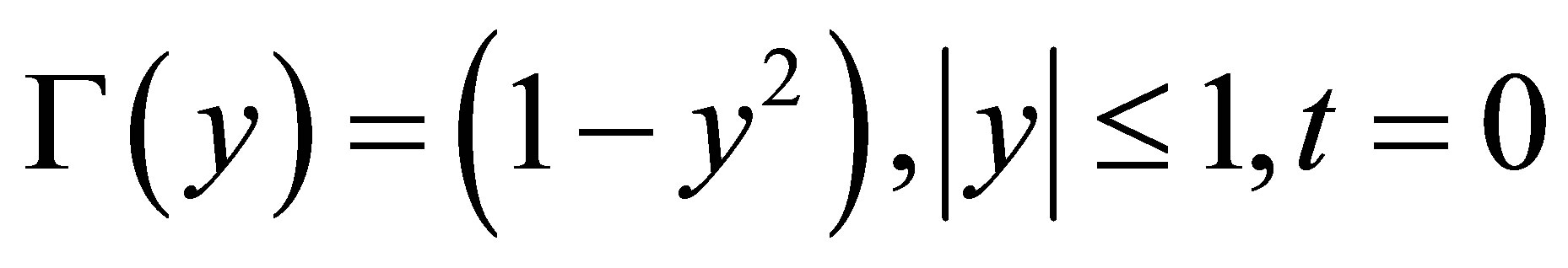
 . It can be easily verified that the solution of Equation (1) for an elliptic planform, untwisted wing out of ground effect (OGE) has an elliptic spanwise distribution of bound circulation and the elliptic wing loading is the optimal value for minimum induced drag within the limitation of flat rigid wake assumption. When a wing is flying in close proximity to the ground, the optimal spanwise distribution of bound circulation is parabolic [13]. Equation (2) shows the equations for bound circulation distributions (for a wing in and out of ground effect) along the spanwise direction, where bound circulations are divided by their maximum values for each case. Thus, it can be said that the nondimensional bound circulation distribution of a wing in ground effect is confined in the envelope with its upper one as an elliptic distribution Equation (2a), and its lower one as a parabolic distribution Equation (2c) (See Figure 1).
Out of Ground Effect: Elliptic Loading,
 (2a)
(2a)
In Ground Effect:
 (2b)
(2b)
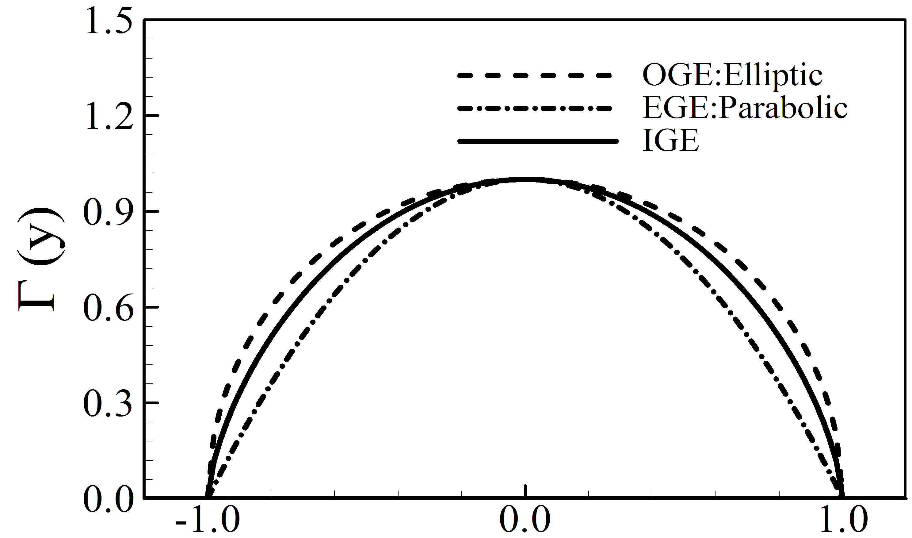
Figure 1. Comparison of spanwise circulation distributions.
Extreme Ground Effect: Parabolic Loading:
 (2c)
(2c)
When applying Equation 2 to the calculation of bound circulation distributions, it is also required to understand the relationship between bound circulation and wing height.
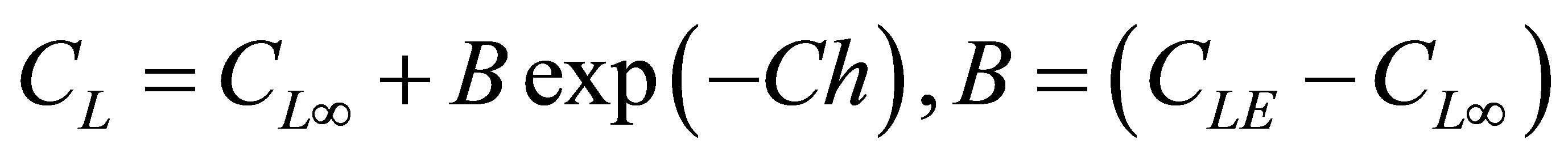
Shigemi et al. [18] performed a wind tunnel test in order to investigate the ground effect on an 8.9% model of HOPE ALFLEX (Automatic Landing Flight Experiment) vehicle. They found an equation for the change of lift coefficient due to the change of the wing height as follows. After modifying the equation in order to match with Equation (2),
 (3)
(3)
where  is the lift coefficient of a wing in free flight (OGE),
  is the lift coefficient of a wing in extreme ground effect (EGE) and C is the coefficient that makes Equation (3) matching with the experimental data and should have a positive value. h represents the distance between the mid chord to the ground.
As shown in Equation (3), the lift coefficient is a nonlinear function of wing height, which also results in the change of circulation distribution. Thus, in the present paper, it is assumed that p in Equation (2b) changes as follows.
 (4)
(4)
where  is set to 1/2. p has the values of 0 and 1 respectively for h = 1.0 and 0.1.
2.2. Unsteady Discrete Vortex Panel Method
Present method is well described and validated in Ref. where the effect of smoothing schemes or vortex models on the numerical accuracy is shown by comparing computed results with the published data of Krasny [10]. In this approach, a lifting line with an initial load distribution is discretized with discrete vortex panel elements (See Figure 2). Each panel segment is assumed to have a constant-strength vortex. This constant-strength vortex panel element is replaced by a single point vortex with
Figure 2. Representation of a lifting line with elliptic loading with discrete vortex panel elements.
the same vorticity. On each line segment, the point vortex is located at the 3/4 point. The trailing wake vortices from each vortex panel element are represented by free point vortices that can deform freely with an assumption of a force-free position.
The distributions of the dimensionless tangential velocities induced by a point vortex are represented using the Lamb (Oseen) model [19]. The Lamb model has a Gaussian distribution of vorticity. Ling et al. [20] proposed a model that is based on the solution for the actual velocity in a viscous fluid. The core radius, rc, is approximately equal to the radial distance of the point where the maximum velocity is induced. This is expressed
 (5)
(5)
The second term on the right-hand side of Equation (5) provides an estimate for the growth in the core radius of the vortex. The vortex Reynolds number is related to the time scale over which the laminar diffusion processes in the vortex core region become turbulent [21]. In the present work, an infinite Reynolds number is assumed. The tangential velocity induced by a point vortex with its circulation, Γj, is as follows.
 (6)
(6)
Several smoothing schemes are used in order to obtain accurate solutions by circumventing the singularity behavior when the distance is very small. Krasny [10] avoids the singularity in the induced velocity of a point vortex through a smoothing factor, δ. The induced velocities because of other vortices can then be written as follows
 (7)
(7)
where  is represented as follows depending on the wing distance to the ground.
 (8a)
(8a)
 (8b)
(8b)
 (8c)
(8c)
In order to enforce the no penetration condition at the ground, an image method is used. Since the wake is force-free, the evolution of each vortex is investigated by moving the positions of point vortices using an Euler convection scheme.
 (9)
(9)
3. Results and Discussion
Figure 3 shows the validation of the present method by comparing the wake shapes behind a lifting line having an elliptic loading with the published result of Krasny [10]. It is assumed that the wing is placed at h = 0 and is out of ground effect. In both calculations, the in-flow velocity and the maximum circulation at the midspan are assumed to be unity. The smoothing factor for the present calculation is set to 0.05 [the same as Krasny’s]. As shown in Figure 4, an unrealistic vortex sheet crossing is not observed in the present results. A time step size of 0.04 sec is used in the present calculation whereas Krasny [10] used a time step size of 0.01 sec. Thus, it can be said that the present results are in agreement with Krasny’s.
Figure 4 shows the comparison of wake shapes behind wings in and out of ground effect. Both wings are placed at the same ground height of h = 1.0. As shown in the figure, wake vortices behind a wing in ground effect cannot fully develop due to the insufficient distance between the wing and the ground. The positions of wingtip vortices of a wing in ground effect are moved laterally
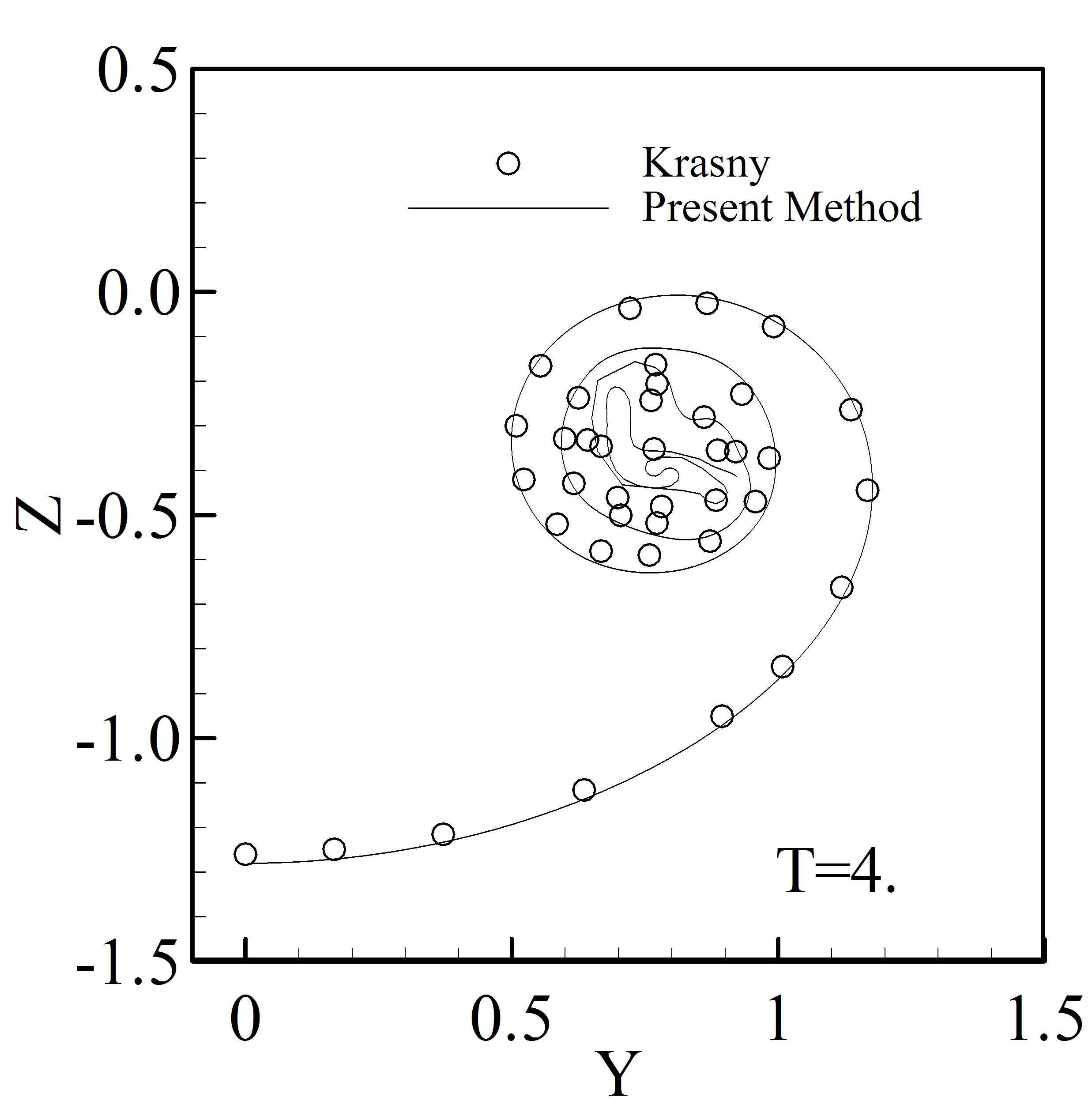
Figure 3. Comparison of wake shapes between present method and Krasny’s.
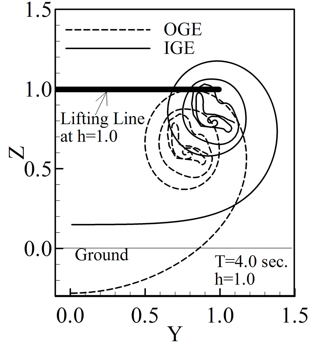
Figure 4. Wake shapes behind a wing in and out of ground effect.
more outward and vertically more upward than those of a wing out of ground effect. When the wing is in ground effect, the desingularized point vortices become confined to a small region and coalesce. Present method does not include the viscous diffusion model of interacting point vortices, but it can be said that the interaction of point vortices while merging will decrease further the viscous diffusion. The total circulation of wingtip vortices behind a wing in ground effect will be decreased.
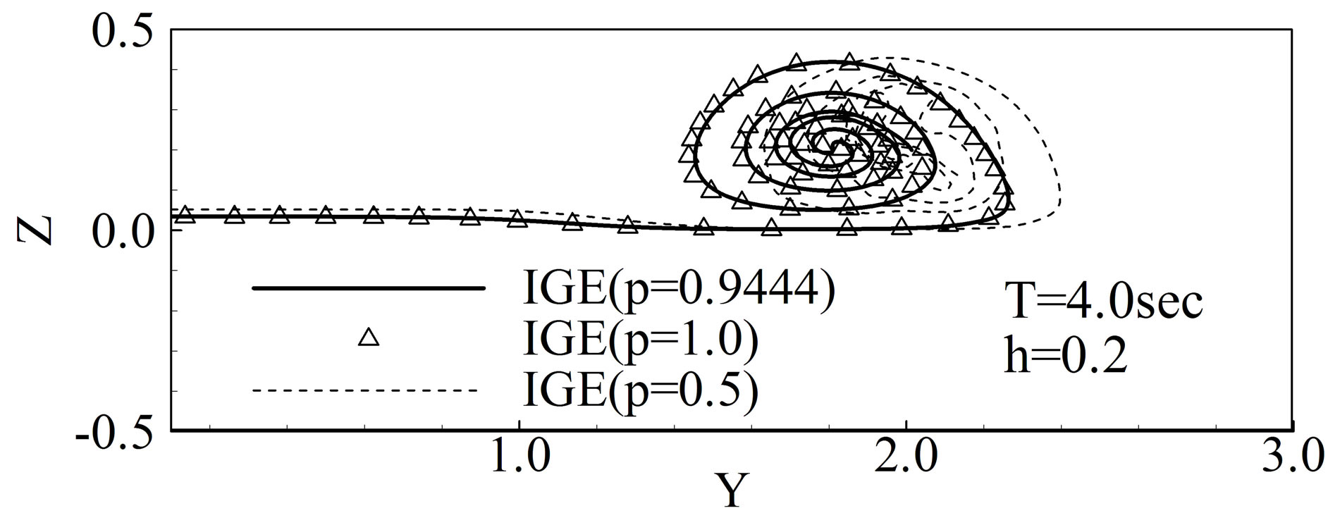
Figure 5 shows the wake shapes behind a wing in close proximity to the ground. When the wing is placed at h = 0.2, from Equation (4), . As shown in Equation (2), p = 0.5 means the elliptic circulation distribution whereas p = 1.0 represents the parabolic circulation distribution. When h = 0.2, the value of exponent p approaches to p = 1.0. Figure 5(a) shows the wake shapes behind a wing at h = 0.2 with three cases of circulation distributions. Figure 5(b) shows the wake shapes behind a wing at h = 0.1 for elliptic and parabolic circulation distributions. As shown in both Figures 5(a) and (b), overall wingtip vortex shapes are similar to each other and does not dependent on the circulation distributions, however, the position of the wingtip vortices for elliptic loading is moved laterally more outward than the other cases. Thus, it can be said that, for a single wing in ground effect, the assumption of elliptic load distributions does not affect much the wake shapes but negligibly changes the position of wingtip vortices.
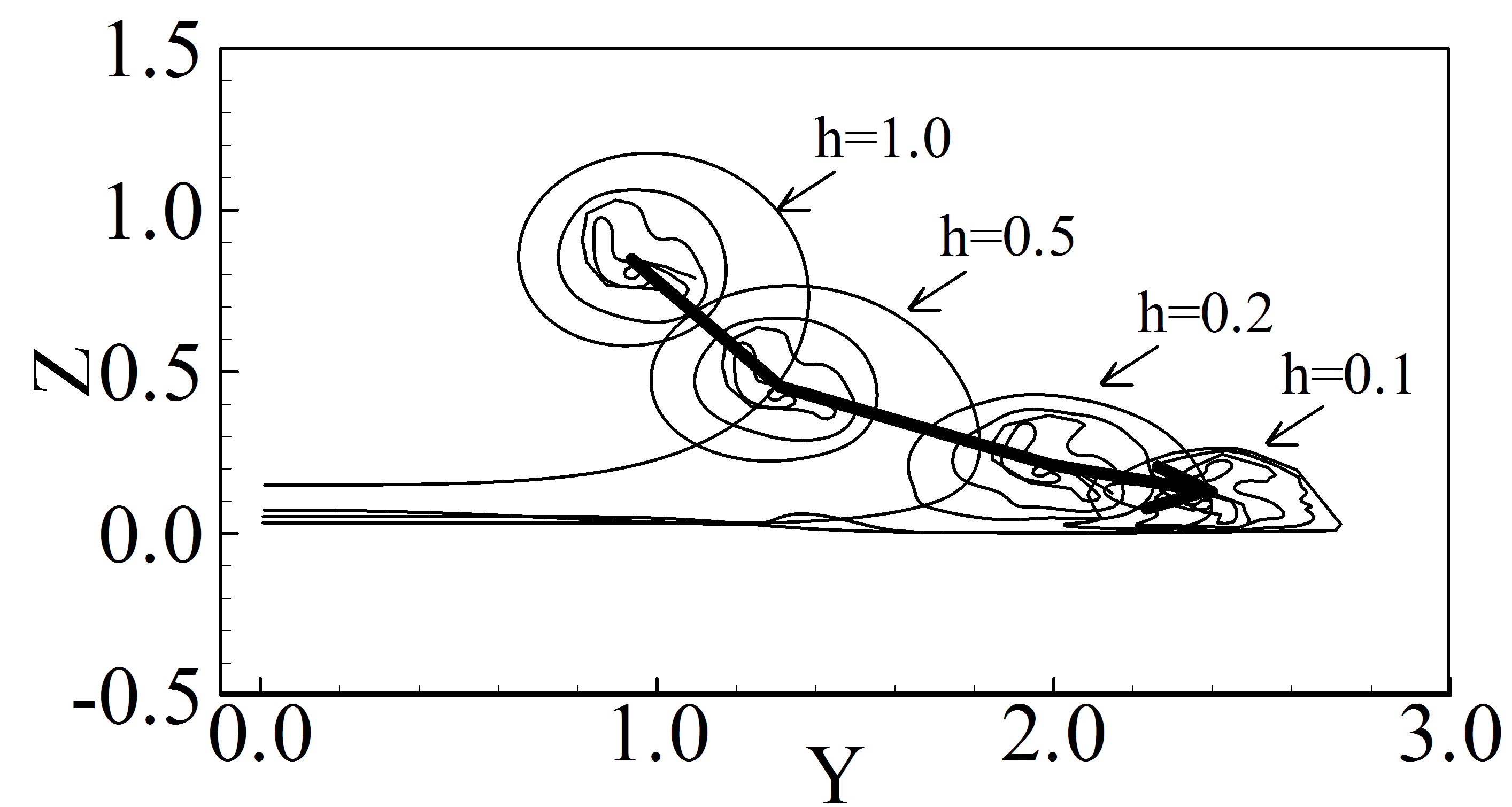
Figure 6 shows the changes of wake shapes behind a wing in ground effect. As the wing is placed close to the ground, the wingtip vortices departed from the wing is moving vertically downward and laterally outward. As shown in Figure 6(b), when the wing is in close proximity to the ground (h = 0.1), the area of confined vorticity is decreased compared to the case of the wing at h = 0.5.
4. Conclusions
In the present paper, a new formula that matches elliptic
 (a)
(a)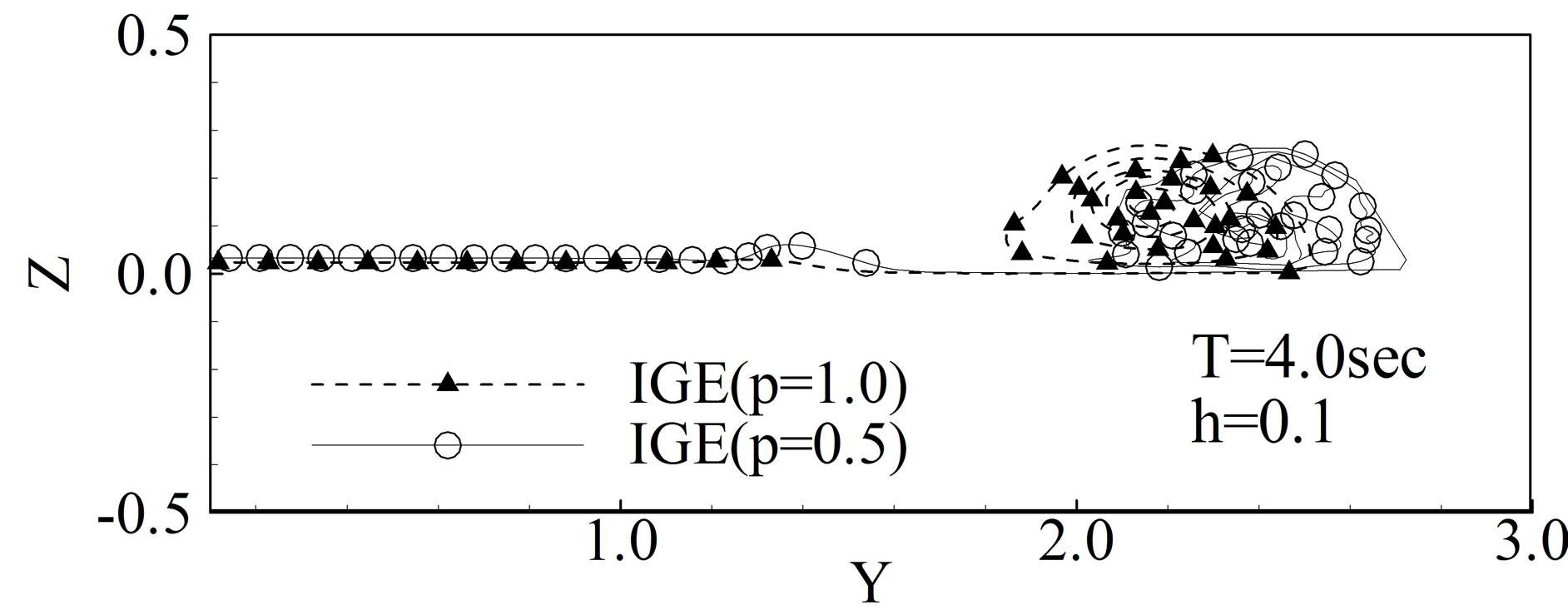 (b)
(b)
Figure 5. Wake shapes behind a wing in close proximity to the ground with various wing loadings.
 (a)
(a)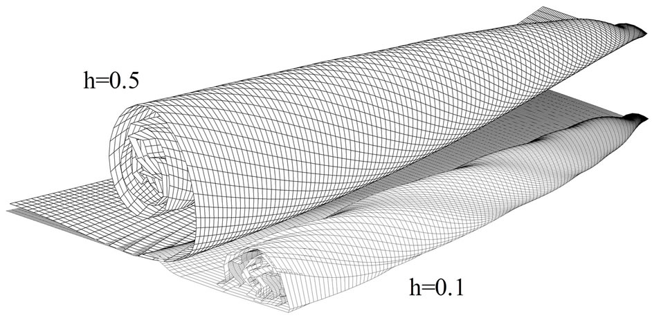 (b)
(b)
Figure 6. Wake shapes for different wing heights. (a) Wake shape in the Trefftz plane, T = 4.0; (b) Three dimensional view of unsteady wake evolutions.
loading for OGE and parabolic loading for EGE is suggested.
From the computed results on the unsteady wake evolution using the suggested model for wing loading, it was found that the overall wingtip vortex shapes were not affected by the wing load distributions. But, as the wing approaches very close to the ground, the parabolic wing load distribution calculation produced more laterally inward wingtip positions than the elliptic load distribution case.
In future, the present model will be applied to the unsteady wake evolution behind wings in formation where the significant interaction between wingtip vortices is expected.
5. Acknowledgements
The research was supported by a grant from the 2011 program for visiting professors overseas in Korea National University of Transportation.
REFERENCES
- K. V. Rozhdestvensky, “Wing-in-Ground Effect Vehicles,” Progress in Aerospace Sciences, Vol. 42, No. 3, 2006, pp. 183-211. http://dx.doi.org/10.1016/j.paerosci.2006.10.001
- K. V. Rozhdestvensky, “Aerodynamics of a Lifting System in Extreme Ground Effect,” Springer, Heidelberg, 2000. http://dx.doi.org/10.1007/978-3-662-04240-3
- H. W. M. Hoeijmakers and W. Vaatstra, “A Higher Order Panel Method Applied to Vortex Sheet Roll-up,” AIAA Journal, Vol. 21, No. 4, 1983, pp. 516-523. http://dx.doi.org/10.2514/3.8108
- R. S. Ribeiro and I. Kroo, “Vortex-in-Cell Analysis of Wing Wake Roll-Up,” Journal of Aircraft, Vol. 32, No. 5, 1995, pp. 962-969. http://dx.doi.org/10.2514/3.46824
- K. Zhu and H. Takami, “Effect of Ground on Wake RollUp behind a Lifting Surface,” Proceedings of the 37th Japan National Congress for Applied Mechanics, Tokyo, 1987, pp. 115-123.
- F. Lamarre and I. Paraschivoiu, “Efficient Panel Method for Vortex Sheet Roll-Up,” Journal of Aircraft, Vol. 29, No. 1, 1992, pp. 28-33. http://dx.doi.org/10.2514/3.46121
- T. Sarpkaya, “Computational Methods with Vortices— The 1988 Freeman Scholar Lecture,” Journal of Fluids Engineering, Vol. 111, No. 1, 1989, pp. 5-52. http://dx.doi.org/10.1115/1.3243601
- D. I. Pullin, “The Large-scale Structure of Unsteady Self-Similar Rolled-Up Vortex Sheets,” Journal of Fluid Mechanics, Vol. 88, No. 3, 1978, pp. 401-430. http://dx.doi.org/10.1017/S0022112078002189
- R. Krasny, “A Study of Singularity Formation in a Vortex Sheet by the Point-Vortex Approximation,” Journal of Fluid Mechanics, Vol. 167, 1986, pp. 65-93. http://dx.doi.org/10.1017/S0022112086002732
- R. Krasny, “Computation of Vortex Sheet Roll-Up in the Trefftz Plane,” Journal of Fluid Mechanics, Vol. 184, 1987, pp. 123-155. http://dx.doi.org/10.1017/S0022112087002830
- M. Morky, “Numerical Simulation of Aircraft Trailing Vortices Interacting with Ambient Shear or Ground,” Journal of Aircraft, Vol. 38, No. 4, 2001, pp. 636-643. http://dx.doi.org/10.2514/2.2840
- C. Han and J. Cho, “Unsteady Trailing Vortex Evolution Behind a Wing in Ground Effect,” Journal of Aircraft, Vol. 42, No. 2, 2005, pp. 429-434. http://dx.doi.org/10.2514/1.6477
- S. E. Windall, and T. M. Barrows, “An Analytic Solution for Twoand Three-Dimensional Wings in Ground Effect,” Journal of Fluid Mechanics, Vol. 41, No. 4, 1970, pp. 769-792. http://dx.doi.org/10.1017/S0022112070000915
- A. Plotkin and C. H. Tan, “Lifting-Line Solution for a Symmetrical Thin Wing in Ground Effect,” AIAA Journal, Vol. 24, No. 7, 1986, pp. 1193-1194. http://dx.doi.org/10.2514/3.9413
- J. Anderson, “Fundamentals of Aerodynamics,” 5th Edition, McGraw Hill, New York, 2010.
- J. Katz and A. Plotkin, “Low Speed Aerodynamics,” 2nd Edition, Cambridge University Press, Cambridge, 2001. http://dx.doi.org/10.1017/CBO9780511810329
- I. G. Sheldon, “Wing Tip Vortices,” In: I. G. Sheldon, Ed., Fluid Vortices, Kluwer Academic Publishers, Berlin, 1995, Chapter X.
- M. Shigemi, T. Fujita, A. Iwasaki, T. Ohnuki, K. Rinoie, H. Nakayasu and M. Sagisaka, “Experimental Investigation of Static and Dynamic Ground Effect on HOPE ALFLEX Vehicle,” Technical Report of National Aerospace Laboratory TR-1236, National Aerospace Laboratory, Tokyo, 1994.
- A. Ogawa, “Vortex Flow-CRC Series on Fine Particle Science and Technology,” CRC Press, Boca Raton, 1940.
- G. C. Ling, P. W. Bearman and J. M. R. Graham, “A Further Simulation of Starting Flow around a Flat Plate by a Discrete Vortex Model,” Internal Seminar on Engineering Applications of the Surface and Cloud Vorticity Methods, Vol. 51, No. 14, 1986, pp. 118-138.
- J. G. Leishman, “Principles of Helicopter Aerodynamics,” 2nd Edition, Cambridge University Press, Cambridge, 2000.
NOTES
*Corresponding author.