

Open Journal of Applied Sciences
Vol.06 No.06(2016), Article ID:67710,18 pages
10.4236/ojapps.2016.66036
A Preliminary of Dynamic Stability Analysis
―The Methods of Dual Mode and Single Mode
Ren Song1, S. X. Wu2
1WUYI University, Jiangmen, China
2Self-Employed (Engineer)

Copyright © 2016 by authors and Scientific Research Publishing Inc.
This work is licensed under the Creative Commons Attribution International License (CC BY).
http://creativecommons.org/licenses/by/4.0/



Received 10 May 2016; accepted 24 June 2016; published 27 June 2016
ABSTRACT
On account of the traditional method in hybrid stability analysis being too rough, a new method of taking dual or single mode was put forward for 4 typical levers in the hybrid stability analysis respectively and transited to the dynamic analysis smoothly. After verifying the superiority of the method through examples, the broad application prospect would be given in the end.
Keywords:
Motel, Dynamic Stability Analysis, Dual Model Method, Single Model Method, Length Coefficient, y(n)-Simulation Method, The Nature of the Lower Limit

1. Introduction
In the traditional hybrid lever stability analysis, its weight is usually ignored or simply put onto the top and bottom nodes proportionally, then calculates the critical load ignoring the lever weight ( [1] p. 107) to simplify the calculation. It is not hard to find that the technique is too rough and the error in dynamic stability analysis will increase with the acceleration of the more serious as the accurate range of analyzed result only exists in the 2 extreme states considering either the top loading or the lever weight only (that doesn’t exist objectively). However, only the space between the 2 extreme ends does be the needs of the reality. Consequently, improving the precision of the intermediate state is of great significance. How to make use of both ends of accurate results, with a continuous function connecting the two is what will be introduced in this paper.
Below the concept of length coefficient connecting the two extreme ends, it will be put for word adopting the way of dual or single mode to realize the hybrid stability analysis first, then evolves to dynamic stability analysis smoothly increasing the accuracy greatly, hoping to provide some improvements to the related industries such as space exploration, seismic structure engineering and high-speed transport etc. having to face high acceleration.
First of all, several concepts will be emphasized or put forward.
Model: The functions of  describing the lever axis of critical state;
Hybrid stability analysis: The stability analysis considering both the top load P and the lever weight (in a unit length) q;
Dynamic stability analysis: The hybrid analysis considering the encountered acceleration also;
Energy method ( [1] p. 88): A very extensive method for stability analysis in which the defect in static method of too complicated in calculation can be avoided; normally gets the approximate results of the larger only;
The nature of the lower limit (in energy method) [2] : Considering the true one as the lower limit of analyzed results in energy method, as narrated in [1] P90: the critical load becomes larger than the true one. Here just continue formulating ( [2] p.2) to call it the nature of lower limit;
BC: The abbreviation of Boundary Condition;
Dual model method: Analyze the lever critical loads with double models;
Single model method: Analyze the lever critical loads with a single model;
Limit length: The extreme length of a prismatic cantilever compressive bar with no top loading;
The length coefficient : The ratio of the actual length
  over the limit one
  called the length
coefficient (of Lever i in model j), that is  (when
(when ) or
) or  (when
(when );
);
Reduction factor : The factor cutting the critical load directly;
Area coefficient: The ratio of the actual section area  over a corresponding square area
  with the same moment of inertial, that is:
Theoretic weight: When the lever weight (in a unit length) is described with the bending stiffness  and
and
the extreme length l of a cantilever with no top loading as  ( [1] p. 103, the extreme length of the
lever being marked as  in this paper) called the theoretic weight of the lever;
Actual weight: The actual lever weight (in a unite length usually do not equal to the theoretic on) would be taken as ;
;
Weight coefficient: The actual weight (in a unit length) over the theoretic one being equal to the Area
coefficient, called the weight coefficient, that is ;
;
In order to make the text concise and clear, below agreed to use “A ≥ B” instead of “proposition B could be derived by proposition A” and agreed upon in the formula that “l” to be the length of the lever; “z” to be a variable with no dimension and “x” to be the one with the length dimension; “a” to be a micro constant with the dimension of moment. Also, the levers discussed below are all prismatic, no longer prompt.
2. The Hybrid Stability Analysis for Several Typical Levers―Dual Model or Single One
Up to now, what could be seen about the hybrid stability analysis is that either ignoring the weight or putting the total weight of  on to the upper and bottom sections proportionally, then analyze with the method considering the top loading only in reference in order to simplify the calculation ( [1] p. 107).
As the matter of fact, the space between the two extreme ends of ignoring either the top loading P or the lever weight q is very large; anyhow of putting the weight to the up and bottom nodes by a fixed proportion cannot satisfy the diversity of the reality, the situation of too rough would be inevitably. However, in order to improve the accuracy of hybrid analysis, creating a connection of continuous function between the two ends may be the only option and the establishment of the concept of the length coefficient is the key to achieving this goal.
Below, the dual and single model methods of stability analysis for the 4 kinds of typical levers in Figure 1(a)-(d) would be introduced first, then transit to the dynamic stability analysis.
2.1. Lever 1
A cantilever compressive bar as Figure 1(a) would be called Lever 1.
If the length , q and
  are all known as constants, the critical load
  would be discussed with the dual mode method below.
Model 1-1 (means lever 1-model 1)
Suppose  and
and  (the first subscript indicates the Lever number; yet the second one does the model number corresponding to the exact solution ignoring q ( [1] p. 47).

BC on A: 
Then 
And 
Equaling  and
and  gives
gives 
 (11-1a)
Below will derive several important values associated with model 1-1 from (11-1a) (Due to the following 2 formulas corresponding to the 2 vastly different states of the lever; 2 kinds of symbols as  and
and  indicating the bar length would be taken to conform them).
If , then
  ( [1] P48) (11-2a)
(The first digit 0 in the subscript indicates on the premise of , for
, for  is a constant of exact value in this case, a 2 digit subscript as
  indicating the premise and the lever number is applied conforming the relations among
 ,
,  and
and  or
or ).
).
If , means that
  (the limit length of this model)
Then  (11-1b)
(The last digit 0 in the manuscript indicates on the premise of ;
;  and
and  are not the exact ones keeping a 3 digit subscript, the same below)
Rewrite the above formula as: (11-2b)
Taking  in (11-1b) to replace q in (11-1a), a hybrid expression of critical load would be:
 (11-3a)
Obviously in the above that  (11-3b)
( ,
, are called the reduction factor of the critical load and the length coefficient of model 1-1 respectively).
Discussion 1-1
We can see by (11-3a) that when ,
, , it conforms to the actual situation; whiles when
 ,
,  ,
,  and
and ; it is quite difference from the exact one of
 ( [1] p. 103). Visible there are flaws in model 1-1. After all, (11-3a) reflects the rough relationship
between  and
and  (see straight line AC in Figure 2) making the hybrid analysis to be in the early dawn now.

Figure 1. 4 kinds of typical Levers.
Model 1-2
Suppose  and
and  (from [2] , method 6 in example 2 in which the stability
analysis considering only the lever weight q with the error being just about 0.023%; although it is not as good as that of 0.0056% of method 9 in the example, to maintain the function with integer power simplifying the calculation, the trail function  corresponding to method 6 with the precision being high enough, is adopted here).
BC on A:


And 
Equaling  and
and  gives
gives 
 (12-1a)
Imitating model 1-1, below will derive several important values associated with model 1-2 (Due to the following 2 formulas corresponding to the 2 vastly different states of the lever, 2 kinds of symbols  and
and  would be taken in the following for the length of the lever)
If , then
  (12-2a)
(The first digit 0 in the subscript indicates on the premise of , a 3 digit subscript indicates that it is not the exact one).
If ,
,  (the limit length of
  in model 1-2)
then  ( [1] P103) (12-1b)
(The last digit 0 in the subscript indicates on the premise of ; then
 ,
,  called the theoretical weight of lever 1; as
  belongs to a approximate exact value of
 ; a 2 digit subscript is given showing the primes and lever number, approximately match the relationship among q, EI and l)
Rewrite (12-1b) as  (12-2b)
( and
and  are called the extreme length of Lever 1 in case of
 )
)
Following the deriving of (11-3a): replace q in (12-1a) with  in (12-1b), the corresponding expression would be:
  (12-3a)
Obviously in the above that  (12-3b)
( and
and  are called the critical load reduction factor and the length coefficient of model 1-2 respectively).
Discussion 1-2
Although  derived from model 1-2 has very high accuracy, it also exposes its own weakness, when
 and
and  is obviously too large and must be improved. Anyway, model 1-2
provides a supplementary to model 1-1, see summary 1 below.
Summary 1
The same form and trend of the reduction factors of (11-3b) and (12-3b) are derived from different of model 1-1 and model 1-2; but it is obvious that  and
and ; it could be explained by the difference of the 2 models: Model 1-1 is derived by static ignoring the lever weight q, making the result of
  to be the exact one ( [1] p. 48), yet, the accuracy of
  is very poor. However, for model 1-2 comes from the condition of no top loading considering the lever weight q only, such an approach makes the precision of
  very high, yet the precision of
  is quite poor. Visible that each model has its own strong point; can this be made use of advantages to achieve a high precision for hybrid stability analysis? As long as to choose the appropriate result according to “the nature of lower limit”, the problems would be solved smoothly. Just calculate
  and
and  taking the smaller would be ok.
There are 2 supplements should be put forward below.
(1) An argument for the above conclusion
It is instructing in Figure 2: First of all, confirm A and B in Figure 2(a), according to (11-2a) and (12-2a). Suppose that E in Figure 1(a) is the intersection of the 2 lines mentioned and the abscissa of E is .
.
Then  or
or 

That is ; If
; If , then
 , C and D would be confirmed. Straight line AC and BD are the images of the functions
  and
and . A is the only precision point in AC, while D is the one in BD.
Obviously,  on the left part of E (the intersection of the 2 lines, when
  is smaller) and
  in the right part of E. (when
  is larger); it provides a simple way for selecting and inspecting: Just calculate
  and
and  according to (11-3a) and (12-3a), taking the smaller one would be ok! Obviously, the effective image is the solid line AED, while the invalid image is the dotted line BEC, a straight line AD would pass point E’ as shown in Figure 2(b) (a detail view the local part of EE).

Figure 2. The straight line method sketch.
(2) The simplified method for calculating the critical load―the straight line method
It looks very close between the broken line AED and straight one AD; if the differences between the 2 at the sections are not so large, it will reduce the amount of calculation greatly using the method of the straight-line AD. Obviously the largest difference between the 2 lines is at section E (E’). As long as the difference between the 2 would be calculated, whether the scheme is feasible could be determined.
The abscissa of E is,  or
or ,
,
Then 
And , confirming that
 .
.
Obviously, the equation of the straight line AD is: (SL)
(SL)
Taking  in (SL), then
The difference between the value  of E' (in the straight line AD) and that
  of E
of E
(in the broken one AED) is about 5.2% being the largest difference between the 2 lines, showing that the method of straight line AD is suitable for calculate the hybrid critical load of Lever1 tending to security. Surely now readers have been found, precise two points A and D have been connected by a continuous function (SL).
2.2. Lever 2
A simply supported compressive bar as Figure 1(b), would be called lever 2.
Suppose that length , the weight q and the bending stiffness
  are all known, the critical load
  would be discussed below.
Model 2-1 (means lever 2-model 1)
Suppose  and
and  called the model 2-1 (corresponding to the exact solution ignoring q ( [1] p. 49)

According to the symmetry of function of m above, we have

And 
As a complete sine wave is symmetry with the center shaft,  could be calculated by putting the top loading
P and the total weight  on to the middle point C equivalently (the vertical displacement being
  (see the calculation of
  in model 1-1), then we got.

Equaling  and
and  gives
gives 
 (21-1a)
Bellow will derive several important values associated with model 2-1 (Due to the following 2 formulas corresponding to the 2 vastly different states of the bar; 2 kinds of symbols as  and
and  indicating the length would be taken to conform them).
If , then
  ( [1] p. 49) (21-2a)
(The first digit 0 in the subscript indicates on the premise of , for
, for  is a constant of exact value in this case, a 2 digit subscript as
  indicating the premise and the lever number is applied conforming the relations among
 ,
,  and
and  or
or ).
).
If , then
  (the limit length of
  in this model),
Then  (21-1b)
(The last number 0 in the subscript indicates on the premise of ; then
  and
and  are not the exact ones keeping a 3 digit subscript).
Rewrite (21-1b) as  (21-2b)
With reference to the derivation of (11-3a), take  in (21-1b) to replace q in (21-1a), the formula corresponding to the critical load would be:
 (21-3a)
Obviously in the above: (21-3b)
( ,
, are called the reduction factor of the critical load and the length coefficient of model 2-1 respectively).
Discussion 2-1
We can see from (21-3a) that when ,
, , it is realistic; whiles
  then
then 
and  (21-1b), must be too large according to the nature of lower limit and the derivation
of model 1-1, it should be improved. Of course, similar to formula (11-3a), (21-3a) reflects the relationship between  and
and  roughly (see straight line BD in Figure 2(a)), laying some foundation for the hybrid analysis.
Model 2-2
Suppose  and
and  (Satisfies
 )
)


BC:  and
and 

And 
Equaling  and
and  gives
gives

 (22-1a)
Imitating model 1-2, below will derive several important values associated with model 2-2 (Due to the following 2 formulas corresponding to the 2 vastly different states of the bar, 2 kinds of symbols  and
and  would be taken to conform them).
If , then
  (22-2a)
(The first subscript 0 indicates on the premise of , the 3 digit subscript indicates that the value is not an exact one).
If  means
means , then
 (22-1b)
(The final subscript 0 indicates on the premise of ; the 2 digit subscript indicates the value is an exact one or its approximation, would be proved in supplement 2-2 below).
Rewrite the above formula as: (22-2b)
( is called the approximation of the limit length in model 2-2).
Taking  in (22-1b) instead of q in (22-1a), the corresponding expression would appear as:
 (22-3a)
Obviously in the above formula that  (22-3b)
( and
and  are called the reduction factor of the critical load and the length coefficient of model 2-2 respectively).
Discussion 2-2
Although the precision of  derived from model 2-2 is very high (see Supplement 2-2), it expose its own short board that when
 ,
,  is too large obviously and must be improved. Anyway, model 2-2 provides some supplement to model 2-1, see line BD in Figure 2.
Supplement 2-2:  in (22-1b) is the weight limit approximation without top loading; our confidence comes from the following inequality:

It shows that the accuracy of model 2-2 is higher than that of model 1-2.
Comparing (22-3a) with (12-3a), it is clear that except to the subscripts, the rest of the formulas are all the same; Of course the straight line method in (2) of Summary 1 is also apply here.
2.3. Lever 3
A directional lever (freely in vertical direction) compressive bar as Figure 1(c) would be called Lever 3.
If the length , the weight q and the bending stiffness
  are all known, the critical load
  would be discussed.
Model 3-1 (means Lever 3-model 1)
Suppose  and
and  (the exact solution ignoring the weight q ( [1] p. 49)

BC on C: 

The external work  could be done by putting the top loading P and the total weight
  on to the middle point C equivalently as:
 .
.
Equaling  gives
gives
 or
or  (31-1a)
Bellow will derive several important values associated with model 3-1. Due to the following 2 formulas corresponding to the 2 vastly different states of the bar; 2 kinds of symbols as  and
and  indicating the bar length would be taken as:
If , then
  (the exact solution: [1] p. 49) (31-2a).
(The first digit 0 in the subscript indicates on the premise of , for
, for  is a exact constant in this case, a 2 digit subscript as
  indicating the premise and the lever number is applied conforming the relations among
 ,
,  and
and ).
).
If , means
  (the limit length in this model)
then  (31-1b)
(The final subscript 0 indicates on the premise of ).
).
Rewrite the above formula as: (31-2b)
With reference to the derivation of (11-1b) taking  to replace q in (31-1a), the corresponding critical load would be:
 (31-3a)
Obviously in the above: (31-3b)
( and
and  are called the reduction factor of critical load and the length coefficient respectively).
Discussion 3-1
According to the experience of model 1-1 and model 2-1, this model also provides the exact value of , but
, but  must be too large, should to be improved. Anyway, (31-3a) reflects the relationship between
  and
and  roughly (see straight line AC in Figure 2), laying some foundation for the hybrid analysis.
Model 3-2
Suppose  and
and , satisfying
 , satisfying
 , satisfying
 , satisfying


Equaling  and
and  gives
gives 
 (32-1a)
Below will derive several important values associated with model 3-2 (Due to the following 2 formulas corresponding to the 2 vastly different states of the bar, in order to keep the size of  constant, 2 kinds of symbols
  and
and  would be taken to conform them).
If , then
  (32-2a)
(The first digit 0 in the subscript indicates on the premise of ).
).
If  means
means  and
and  (the limitation of length of this model) then,
 (32-1b)
(In the coming Supplement 2-3 will prove that it is the approximation of the exact solution,  is adopt)
Rewrite (32-1b) as  (32-2b)
( and
and  are all called the limit length of model 3-2).
Following the deriving of (22-3a): replace q in (32-1a) with (32-1b), the corresponding expression will be:
 (32-3a)
Obviously in the above that  (32-3b)
( and
and  are called the critical force reduction factor and the length coefficient of model 3-2 separately).
Discussion 3-2
Although the precision of  derived from model 3-2 is very high (see Supplement 3-2), it expose its own short board that when
 ,
,  obviously is too large and must be improved. Anyway, model 3-2 provides some supplement to model 3-1, see line BD in Figure 2.
Supplement 3-2 (following Supplement 2-2): As the exact value  could not be found at present, we have enough confidence to take
  as the similar one, which comes from the (approximate) equation:
 , indicating that the
accuracy of model 3-2 and model 1-2 are very close. Of course, I also hope to have the ability (conditions) readers solve the exact critical load q for the lever, making the problem clearer and no suspense.
Comparing (32-3a) with (12-3a), it is clear that except to the subscripts, the rest of the formulas are all the same; Of course the straight line method is also apply here.
The dual mode method for three Levers has been introduced above; if there is no second model for the Lever to be discussed, the single mode method has to be applied.
2.4. Lever 4
A directional lever (freely in horizontal) compressive bar as Figure 1(d) would be called lever 4.
If the length , the weight q and the bending stiffness
  are all known, the critical load
  would be discussed below. As there is no second model (would be discussed in the following), the symbols in the formulas would be taken with a single digit subscript 4 indicating the lever number only.
Model 4
Suppose  and
and  (It is the model of central symmetry called the model 4 being the exact model in condition of
  [1] p. 49)

BC on A: 

Taking the equivalent concentrated load on C to calculate : Just delete the algebraic term containing q and take
  to instead of P in the formula of
  in model 1-1,
That is: 
Equaling  and
and  gives
gives 
 (4-1a)
(Following the analysis in the above models, 2 symbols would be taken in the following formula).
The conclusion in model 1-1 indicates that formula (4-1a) is the exact solution for both P and q, then:
If , then
  (4-2a)
(The first digit 0 in the subscript indicates on the premise of ).
).
If , then
  (4-1b)
(The last number 0 in the subscript indicates on the premise of ;
;  and
and  are all the exact or nearly exact ones getting a 2 digit subscript).
Rewrite the above as: (4-2b)
( is called the extreme length in model 4).
Taking  in (4-1b) to replace q in (4-1a), the hybrid expression of critical load would be:
 (4-3a)
Obviously in the above that  (4-3b)
( and
and  are called the critical load reduction factor and the length coefficient of model 4 respectively).
Discussion 4
The changing rule of  with
with  has been show clearly in (4-3a): When
 ,
,  and when
 ,
,  and
and  (41-1b). As it is center symmetry model, the 2
values above have been the critical ones for both top loading P and lever weight q. If a better one would be discovered, it must be a good thing for us.
Summary 2
There are 4 kinds of levers have been discussed above, they all have 2 models except lever 4. As there is no best, just better for the second models, hop to see better second models for all kinds of the objects in hybrid stability analysis making the scope of accurate analysis could be widened day by day. Of course, the author also welcomes the opinion of this article making a negative, because the exploration is the precondition of the development of the theory. Denying the wrong conclusion still can prevent the happening of calamity.
3. Area Coefficient and Dynamic Stability Analysis
In order to adapt to the stability analysis for all kinds of cross section levers, below will introduce the concept of the area coefficient, the actual area of the cross section  over the corresponding one of
  with the same moment of inertial of a square cross section. Of course, it is equal to the weight coefficient, the actual weight in a unit length
  over its theoretical value
 ;
;
That is  (5-1)
(5-1)
For the static stability analysis (with no acceleration), the traditional method usually ignore the lever weight or simply distribute it onto the upper and lower note proportionally, then take the method ignoring the lever weight ( [1] p. 105-107) to go on the analyze. However, it is too rough for not considering the factor of the length coefficient impacting on the result greatly, and the situation will increase along with the acceleration as well in dynamic stability analysis. In order to analyze the critical load more accurately undergoing acceleration, below will solve the effect of acceleration on the relevant quantities, namely the related expressions in dynamic stability analysis.
Suppose the objects is subjected to the influence of acceleration of  upward, g is the acceleration of gravity on the earth’s surface, the values contain the factor of q should increase m times to be
  making the static reduction
  become the dynamic one of
  (in case
 ) or
) or  (in case
 ), then the general formula (SL) in the section of Summary 1 turns to be:
If , then
  (SL1)
(SL1)
If , then
  (SL2)
(SL2)
Just calculate the corresponding values in (SL1) or (SL2) can work out the corresponding critical load immediately.
IIn order to make the analysis more convenience, 3 constants for every one of the 4 typical levers related to the above 2 formulas are given in Table 1.
Summary 3
1) The straight line method (in summary 1) would not only suitable for Lever1, but also for lever 2 and lever 3 as well; as there is no second model for lever 4, its analysis becomes even simpler taking (SL2), making the dynamic stability analysis for all kinds of the Levers discussed in this paper become very simple.
2) For the 3 levers having the second model, their maximum errors belong to the same order (of magnitude no more than 5.2%, see the last part in summary 1) according to the following 3 similar formula:
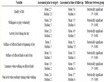
Table 1. The constants associated with dynamic stability analysis.
 (N12)
(N12)
 (N22)
(N22)
 (N32)
(N32)
4. Examples
Below would provide not only the concrete steps for the analysis, but also the fundamental relationship between the critical load and the lever number as well. Also, the results of 4 kinds of Levers encountered 4 values of accelerations are provided in Table 2. In order to simplify the description, only one of the 4 situations is provided in detail for each lever.
The material involving in the examples unified with joist steel of 20a, the relevant data are shown in Table 2, whiles the results analyzed is in Table 3.
Table 2. The data of I steel of 20a ( [3] p. 7.26 and modified by internet (February 2015)).
Data preparing:
Dangerous direction is the one of the smaller moment of inertia: ,
, .
.
Calculating the section area: .
.
Areas coefficient: ; The uniform reduction factor:
 .
.
Actual weight:  (
( comes from (i2-1b)); the theoretical weight:
 ).
).
Example 1. Figure 1(a) shows lever 1 of 20a I steel, if , that is
 , when
 ,
,  ,
,  and
and , calculate the critical load (in the dangerous direction).
Case 1: The upward acceleration is 0 (that is ).
).
The straight line method:
According to (SL1), we have: 
Traditional method: Put the  to the upper note then overlap:

 , comparing with the Traditional method, the synergy is over 3 times.
Example 2. Figure 1(b) shows Lever 2 of 20a I steel, if , that is
 , when
 ,
,  ,
,  and
and , calculate the critical load
 .
.
Case 2: The upward acceleration is  (that is
 ).
).
According to (SL1) (The straight line method), we have:

Traditional method: Add  to the upper note, then:

 , comparing with the Traditional method, the synergy is about 2 times.
Example 3. Figure 1(c) shows lever 3 of 20a I steel,, if , that is
 ,when
,when ,
,  ,
,  and
and , calculate the critical load
 .
.
Case 3: The upward acceleration is  (that is
 ).
).
According to (SL1) (The straight line method), we have:

Traditional method: Add  to the upper note, then:

 , comparing with the Traditional method, synergy is about 29.7%.
Example 4. Figure 3 shows lever 4 of 20a I steel, if , that is
 , when
 ,
,  ,
,  and
and , calculate the critical load.

Figure 3. A structure equivalent to Lever 4.
Case 4: The upward acceleration is  (that is
 ).
).
According to (SL2) (The straight line method), we have:

Traditional method: Add  to the upper note, then:

Traditional method completely lost the carrying capacity, the straight-line method still has considerable bearing capacity.
Table 3. Data summary (the material is I steel of 20a), the unite of  is
is ).
).
Summary4: The results of the examples in this section show that the traditional method is too conservative and the waste situation is very serious with the increasing of the acceleration.
5. Summary and Outlook
With the development of the society and the progress of science and technology, the dynamic stability analysis demand grows with times. Although the theory related to acceleration and stability is also developing fleetly in recent years, it focuses either on the strength fracture of the beams and columns coursing by vertical or horizontal direction acceleration respectively as in [4] or on the stability of columns with no acceleration as in [5] ; the document about instability destruction, is rare indeed. During the earthquake, of course, the vertical and horizontal direction acceleration usually occur at the same time; the strength damage problem, apparently, is more common, but the instability of pillar of vertical acceleration to destruction can’t be rule out; so, about the dynamic stability analysis of the post must be mentioned on the agenda. This is the reason why I push this paper.
I also want to tell the readers that there is only one step away from the conclusion of this article and the framework of the dynamic stability analysis. Because the framework of static stability analysis software has developed very perfect and takes the key pillar of the framework analyzed with the software to dock with one of the four typical levers analyzed in this paper, the problem would be solved. If you are interested, I would be happy to see your achievement. I also want to tell the reader that there is only one step away from the conclusion of this article and the framework of the dynamic stability analysis. Because the framework of static stability analysis software has developed perfectly; just take its key pillar to dock with the paper, which based on the constraint conditions in this paper four typical choice of pressure levers on a corresponding, problem is solved. If you are interested, I would be happy to meet you.
In addition to literature [1] , the author failed to find other references. Although after serious check, errors are still unavoidable. In order to prevent misleading coursing the catastrophe, please readers do more screening, I will be grateful. So here called for readers interested in this issue propose more criticism. In addition, I hope for a conditional institution to confirm (or overturn) the conclusion of this article experimentally, making the dynamic stability analysis theory to go into the practical application stage as soon as possible, letting it become a new power for progress of science, technological and social development.
Cite this paper
Ren Song,S. X. Wu, (2016) A Preliminary of Dynamic Stability Analysis. Open Journal of Applied Sciences,06,347-364. doi: 10.4236/ojapps.2016.66036
References
- 1. Timoshenko, S.P. and Gere, J.M. (1961) Theory of Elastic Stability. 2nd Edition, McGraw-Hill Book Company, Inc., Toronto.
- 2. Song, R. and Wu, S.X. (2015) An Expansion of Boundary Theory and the Application of Joint Condition. Open Journal of Applied Sciences. http://www.scirp.org/journal/ojapps
- 3. Yang, W.Y. (1985) Practical Manual of Civil Engineering. Chinese Communications Press, Beijing. (In Chinese)
- 4. Chopra, A.K. (2005) Dynamics of Structures—Theory and Applications to Earthquake Engineering (Computing Essentials of Second Edition). Tsinghua University Press, Beijing.
- 5. Chen, J. (2010) Stability of Steel Structures—Theory and Design. China Electric Power Press, Beijing.