Modeling and Numerical Simulation of Material Science
Vol.3 No.4(2013), Article ID:37530,7 pages DOI:10.4236/mnsms.2013.34016
Simulation of Graphene Piezoresistivity Based on Density Functional Calculations
1Materials Science and Engineering Department, Egypt-Japan University of Science and Technology, Alexandria, Egypt
2Center for the Promotion of Interdisciplinary Education and Research, Kyoto University, Kyoto, Japan
3Mechatronics and Robotics Department, Egypt-Japan University of Science and Technology, Alexandria, Egypt
4Department of Micro Engineering, Kyoto University, Kyoto, Japan
Email: *Mohamed.gamil@ejust.edu.eg
Copyright © 2013 Mohammed Gamil et al. This is an open access article distributed under the Creative Commons Attribution License, which permits unrestricted use, distribution, and reproduction in any medium, provided the original work is properly cited.
Received March 28, 2013; revised April 28, 2013; accepted May 6, 2013
Keywords: Graphene ribbon; Piezoresitivity; First-principles calculation; Gauge factor
ABSTRACT
The piezoresistive effect in graphene ribbon has been simulated based on the first-principles electronic-state calculation for the development of novel piezoresistive materials with special performances such as high flexibility and low fabrication cost. We modified theoretical approach for piezoresistivity simulation from our original method for semiconductor systems to improved procedure applicable to conductor systems. The variations of carrier conductivity due to strain along with the graphene ribbon models (armchair model and zigzag model) have been calculated using band carrier densities and their corresponding effective masses derived from the one-dimensional electronic band diagram. We found that the armchair-type graphene nano-ribbon models have low conductivity with heavy effective mass. This is a totally different conductivity from two-dimensional graphene sheet. The variation of band energy diagrams of the zigzag-type graphene nano-ribbon models due to strain is much more sensitive than that of the armchair models. As a result, the longitudinal and transverse gauge factors are high in our calculation, and in particular, the zigzag-type graphene ribbon has an enormous potential material with high piezoresistivity. So, it will be one of the most important candidates that can be used as a high-performance piezoresistive material for fabricating a new high sensitive strain gauge sensor.
1. Introduction
One-atom-thick graphene sheet (see Figure 1) is gathering a lot of attention because of its unique electrical and mechanical properties such as high electron mobility and stiffness after its discovery by Novoselov et al. [1]. The piezoresistance effect is defined as the electrical resistivity change under mechanical stress [2]. With the ardent interest to merge graphene into piezoresistor applications, researchers are driven to study the piezoresistance effect of graphene sheets fabricated by various methods. Lee et al. reported that the gauge factor of graphene grown on Ni and Cu films by chemical vapor deposition was 6.1, with 1% applied strain [3]. Chen et al. found that the gauge factor of mechanically exfoliated graphene was nearly 150 [4]. Hosseinzadegan et al. reported that the gauge factor of graphene prepared by chemical vapor deposition on Si/SiO2 wafer was 18,000 [5]. A recent theoretical work predicted that the conductivity of gra-

Figure 1. Single-layered graphene sheet.
phene changed from the conductive state to the semiconductive state by the splitting of band gap due to strain [6], though single-layer graphene is generally impossible to have a band-gap [7]. If a band-gap exists, the straininduced band-gap modulation could be one source of piezoresistivity in graphene [5]. In our previous work [8-13], the simulation of piezoresistivity based on the first-principle band structure has been developed for semiconductor systems. In this work, the gauge factors of graphene models have been evaluated by our original simulation method based on the first-principles band structure with some modifications which can be applied to conductor systems.
2. Method of Calculation
First-principles calculations of the periodic boundary models for graphene have been carried out by FHI98MD program package [14] based on the density functional theory (DFT) [15]. For the DFT exchange-correlation interaction, the generalized-gradient approximation (GGA) method was used by Perdew-Burke-Ernzerhof (PBE) functional [16]. We adopted the three-dimensional supercell approximation technique with norm-conserving pseudopotentials prepared according to the Hamann method [17] and wave functions with plane-wave expansion.
The zigzag and armchair models have been defined as shown in Figure 2, where these models have been devi-
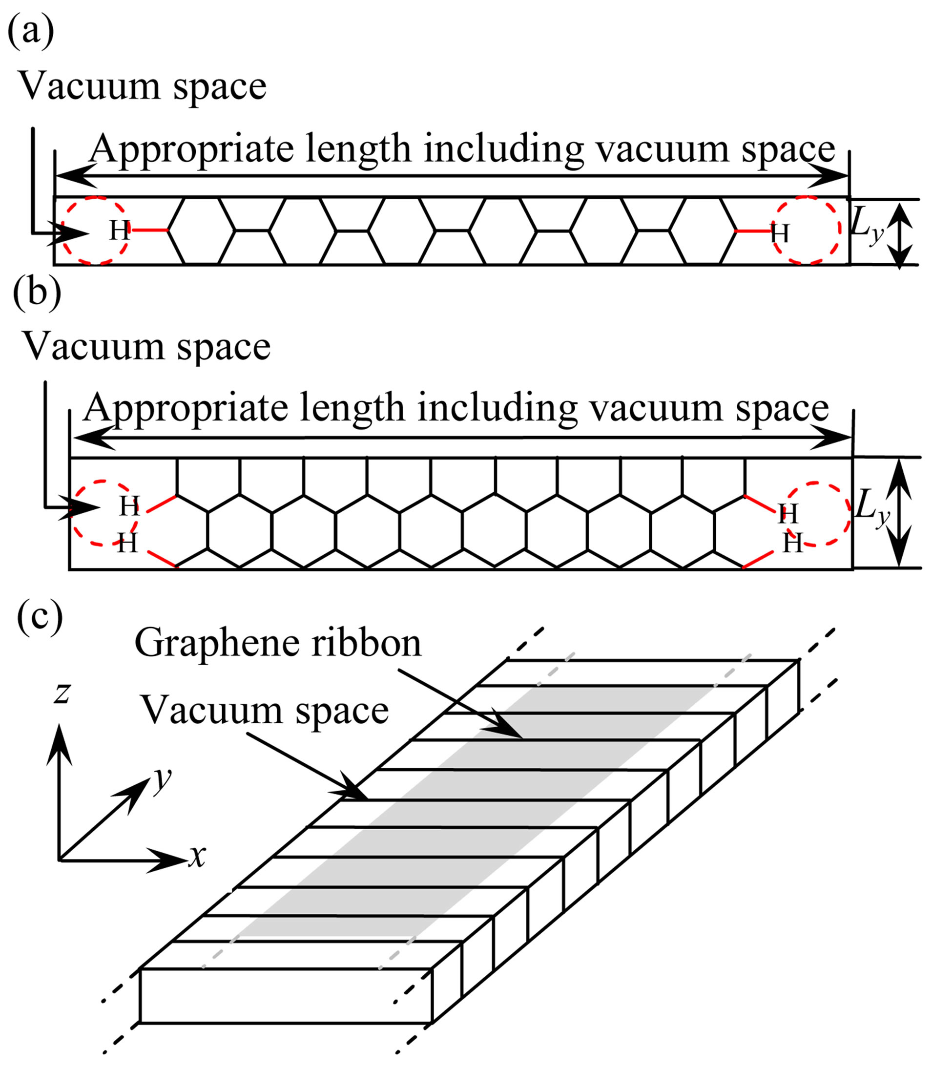
Figure 2. Top views of (a) Armchair model (9 rings) and (b) Zigzag model (13 rings), and (c) 3D-dimensional periodic boundary condition for these models.
sed by cutting out a fragment with a one dimensional periodic boundary, and all dangling bonds of C atoms were terminated with H atoms. The direction of the fragment which is parallel to the y direction can be defined as the longitudinal direction, while the parallel to the x direction can be considered as the transverse direction as illustrated in Figure 2(c). To represent graphene ribbon, vacuum space about 5 Å along x direction is considered.
3. Results and Discussion
3.1. Geometrical Optimization of Graphene Sheet
C-C length of the graphene sheet in the strain-free condition has been optimized by the first-principles calculation. We found that the optimized value of the C-C length of graphene is 1.422 Å which is corresponding to the C-C length for the minimum total energy. This value is completely corresponding to the experimental value (1.42 Å) by Heyrovska [18].
C-C length in the strain condition can be evaluated by using Poisson’s ratio as indicated in Equation (1).
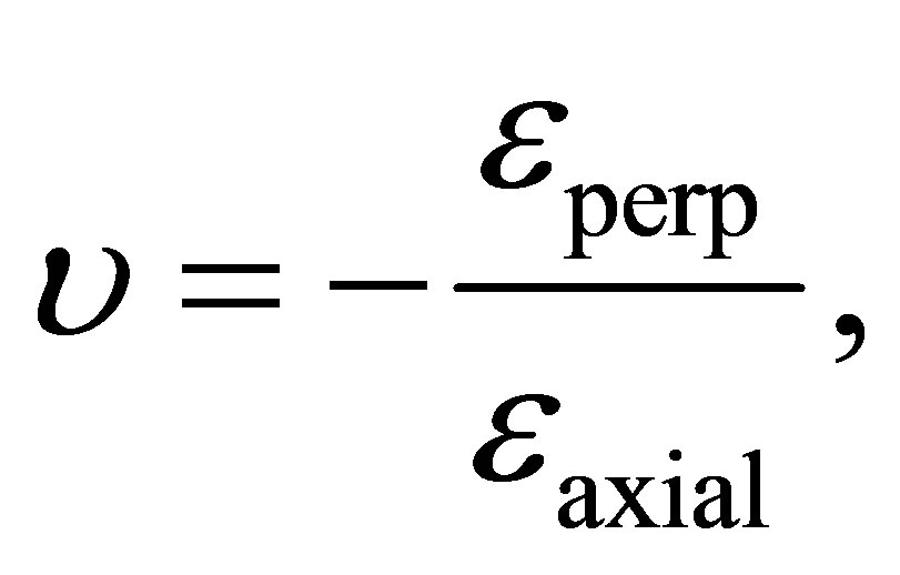 (1)
(1)
where εperp is the transverse strain (perpendicular to the applied load) and εaxial is the axial strain (in the direction of the applied load). The value of υ has been calculated by partial optimization of graphene sheet, where one lattice constant with 1% uniaxial tensile strain is fixed. We investigated two different strain directions: the first is the V strain while the second is the U strain as illustrated in Figure 1. The Poisson’s ratio is determined as υ = 0.28 for the V strain and υ = 0.14 for the U strain. Experimental results of Poisson’s ratio of graphene sheet have given a wide range of values from 0.12 to 0.3 [19-24]. Actually, the results of partial optimization are sensitive and our results υ = 0.28 or 0.14 satisfy the experimental measurements.
We applied the optimized C-C length and Poisson’s ratios to the graphene ribbon models. In this paper, we simulated the 9-ring armchair and 13-ring zigzag graphene ribbon models. The structural parameters of the models shown in Figure 2, number of C atoms (NC), and numbers of H atoms (NH) are tabulated in Table 1.
3.2. Modeling and Calculation of Armchair Models
The whole image of band energy diagram of the 9-ring armchair model is shown in Figure 3. The valence band (VB) maximizes and the conduction band (CB) minimizes at the Y point, respectively, and zero band gap was observed. Accordingly, the armchair graphene ribbon can be considered as a semi-metal or zero-band gap semi-

Table 1. Structural parameters of graphene models.
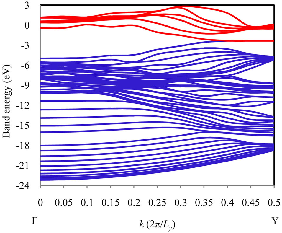
Figure 3. Band energy diagram of 9-ring armchair model. The blue lines are VB subbands and the red lines are CB subbands.
conductor. In detail, the highest VB subband and the lowest CB subband are in double degeneracy at the Y point, in the vicinity of the Fermi energy. This feature can be also derived by the simple Hückel method qualitatively for the armchair model, as shown in Figure 4. As the common characteristic of the armchair models, the π orbitals of all of armchair models are localized at the edges of graphene ribbon, and no conductance path exists in the center of graphene ribbon. The interaction due to π orbitals along the longitudinal direction is very small because of the non-bonding state due to the anti-symmetric relation for the translation with the phase factor , and accordingly, the band energy variation of these degenerate subbands with respect to k point is quite small near the Y point. As a result, low conductivity with heavy effective mass can be explained by using the band orbital interaction. This is one of the most important effects due to miniaturization to armchair-type nanoribbon in the sense that a totally different conductivity from two dimensional graphene sheet can be given.
According to the longitudinal or transverse strain, variations of the band structures of armchair models have been observed. As it is clear from the band energy diagram shown in Figure 5, the degenerate subbands in the vicinity of the Fermi energy are not lifted by the longitudinal or transverse strain effect, and the feature of conductivity based on the band energy diagram will not change so much. These features are in good agreement with quite small band orbital interaction as shown in Figure 4.
3.3. Modeling and Calculation of Zigzag Models
The whole image of band diagram of the 13-ring zigzag model is shown in Figure 6. The VB maximizes and the CB minimizes near the Γ point, respectively. Figure 7 represents the band energies diagrams for the strain-free and strain 13-ring zigzag models. As compared with the armchair models, the variation of band energy diagrams of the zigzag models by the strain is much more sensitive. In particular, the characteristics of VB top and CB bottom subbands near the Fermi energy are caused by both of the longitudinal and transverse strains. Actually, the π orbitals of VB top and CB bottom are delocalized, and the band orbital interaction is easy to be caused due to strains.
3.4. Evaluation of Strain Gauge Factors
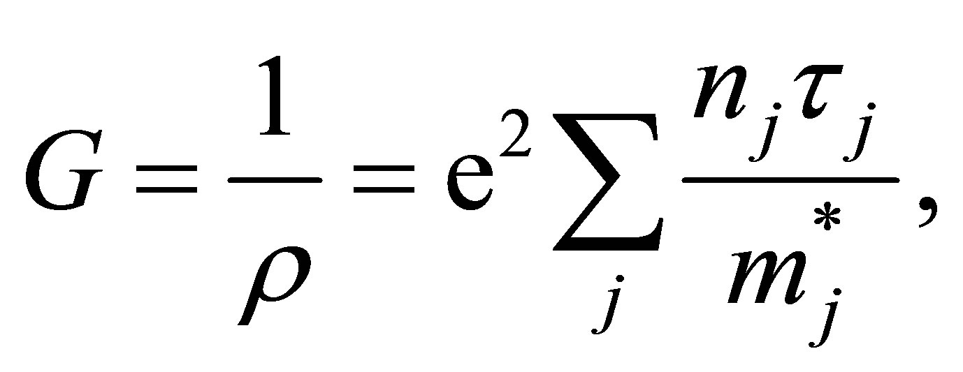
The electrical conductivity G or the electrical resistivity ρ can be represented in terms of carrier density and effective mass by the conventional treatment [25]. Variations of band structure will exert an influence on them, and frequently contribute to a sudden turn of the conductivity. In this paper, we have introduced the band carrier densities for conductive state. The conductivity has been represented as,
 (2)
(2)
where nj is the jth conduction band carrier electron area density, m*j is the band effective masse, τj is the relaxation time, and e2 is the square of the absolute value of the elementary electric charge. The band carrier densities nj are defined with the Fermi energy and temperature T;
 (3)
(3)
where S is the surface area of the graphene model (S = Lx × Ly), 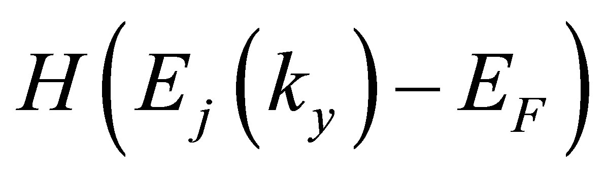 is the Heaviside step function with respect to the band dispersion of jth subband Ej(ky), and kB is the Boltzmann constant. By using the calculated band energy of the jth subband and k-point weight, Ej,ky

Figure 4. Degenerate π orbitals at Y point near the Fermi energy for the 9-ring armchair models with 2 unit cells.
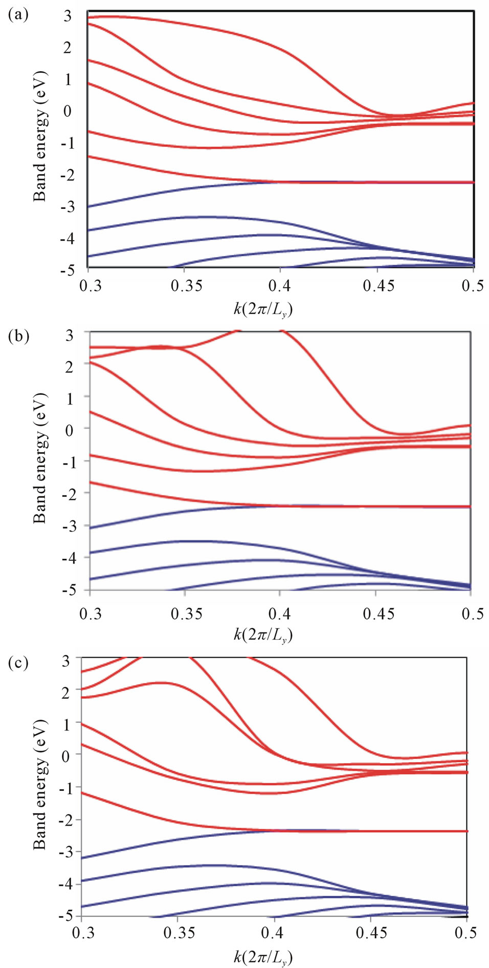
Figure 5. Band energy diagrams for 9-ring armchair (a) No strain model; (b) Longitudinal strain model; (c) Transverse strain model.

Figure 6. Band energy diagram of 13-ring zigzag model.
and 𝑤ky, nj can be approximated as
 (4)
(4)
The value of EF can be solved easily with the total number of valence electrons in the model as follows,
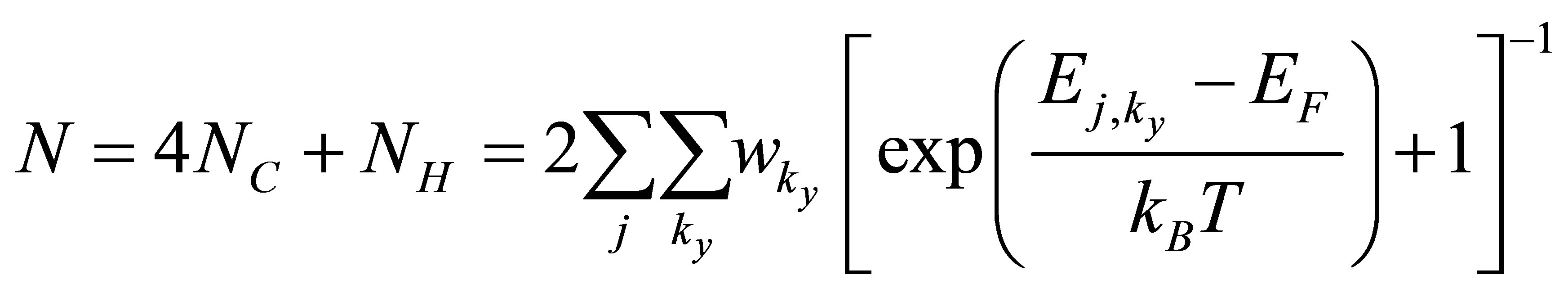 (5)
(5)
We have performed a sampling with 11 points along the Γ-Y path.The effective mass is generally a 3 × 3 tensor, and the reciprocal matrix of effective mass is defined as [26]
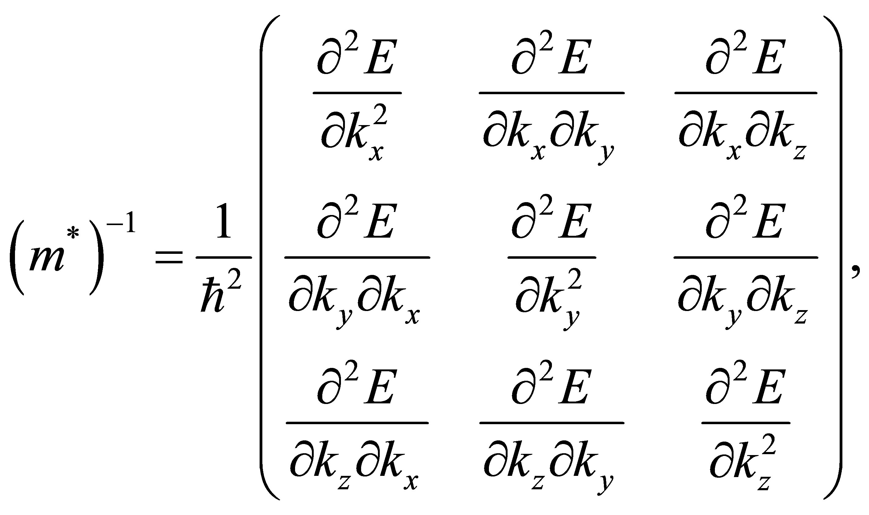 (6)
(6)
where E is the band energy and ħ is equal to Planck’s constant divided by 2π. The band energies of our graphene models remain constant along the transverse directions, namely,
 (7)
(7)
and therefore, the band effective mass of the jth band for the graphene models can be defined simply as a scalar,
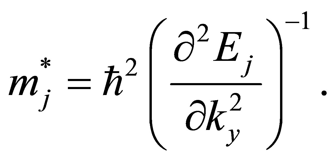 (8)
(8)

Figure 7. Band energy diagrams for 13-ring zigzag (a) No strain model; (b) Longitudinal strain model; (c) Transverse strain model.
In this paper, the second derivative on the right hand of Equation (8) has been estimated numerically as
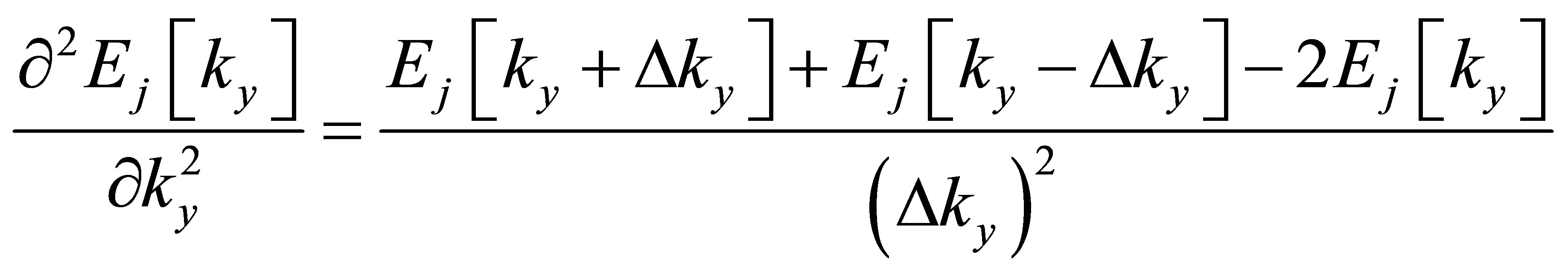 (9)
(9)
with ∆ky = 0.05 × (2π/Ly). For the relaxation time in graphene systems, we have introduced the approximation that all of the band relaxation times are equal and constant regardless of stress [8-13]. This procedure seems to be rough to some extent, but the variation rate of carrier conductivity can be easily and adequately represented in consideration of the canceling of almost part of band relaxation times.
Gauge factor can be defined as,
 (10)
(10)
where Rα and R0 are the graphene resistances at applied strain εα (α denotes longitudinal or transverse) and at no strain, respectively. From Equations (2) and (10), the gauge factor equation can be written as follows:
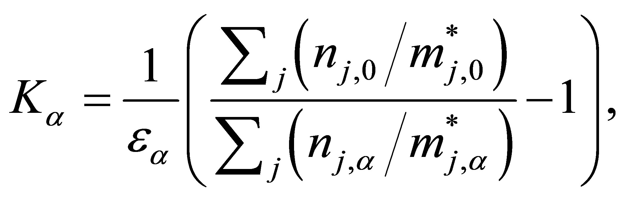 (11)
(11)
Using the data obtained from the energy diagrams which are tabulated in Table 2, we can easily calculate the values of the gauge factors for both armchair model and zigzag model as shown in Table 3.
It was found that the carrier electron area densities of armchair model do not change due to any strains and the effective masses are very large regardless of strains. From the view point of piezoresistivity, the longitudinal and transverse gauge factors seem to be large because the variation ratios of inverse effective masses due to strain become large by high sensitivity with small values. As compared with the armchair model, drastic changes in the carrier electron area densities and effective masses due to strain can be observed in the zigzag model.
4. Conclusion
In this paper, the gauge factors in armchair and zigzag graphene ribbon models have been simulated on the basis of first-principles calculation. The variations of carrier conductivity of graphene ribbon have been calculated using band carrier densities and their corresponding effective masses. We found the different characteristics
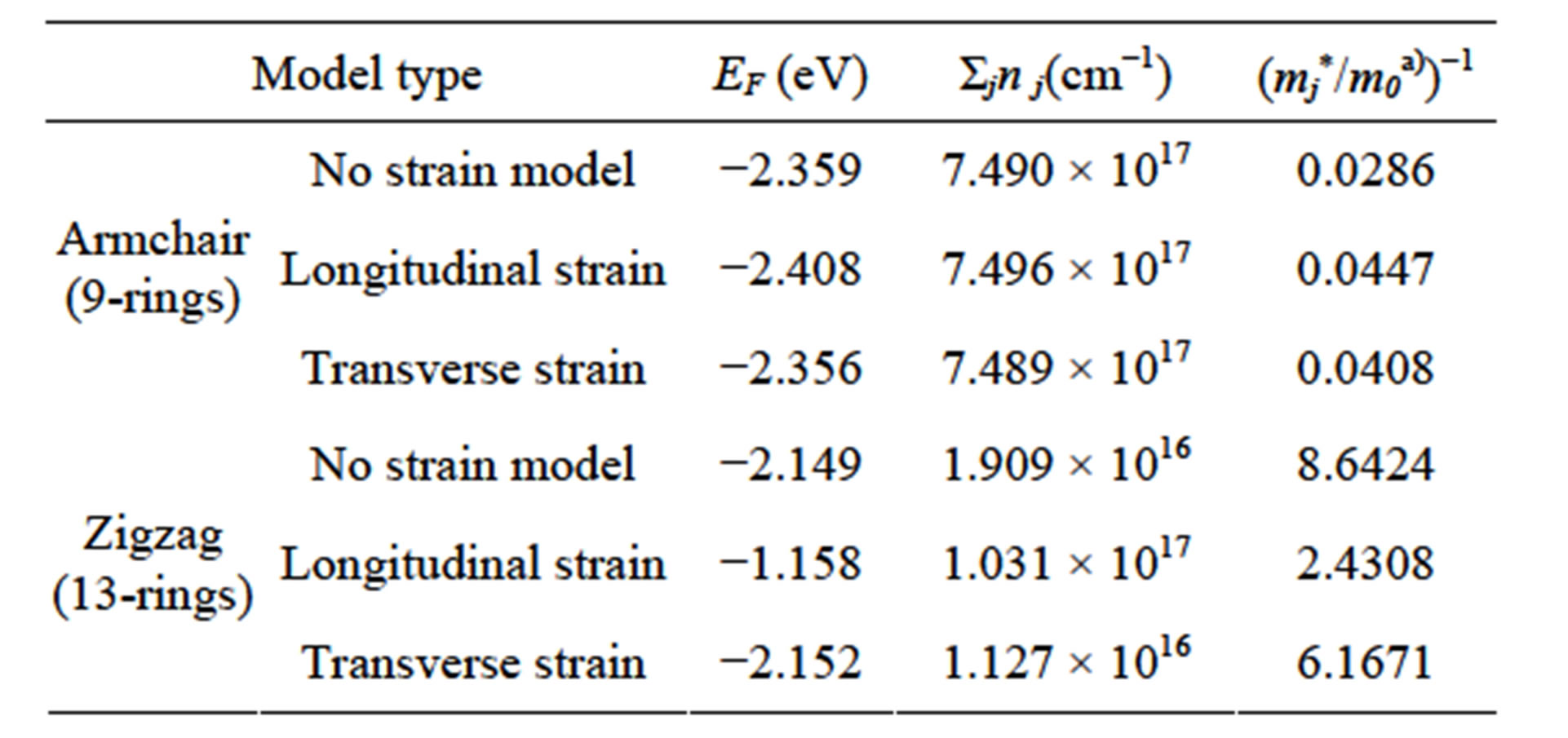
Table 2.armchair and zigzag model properties.

Table 3. Gauge factors of grahene models.
in conductivity between armchair and zigzag models. The longitudinal and transverse gauge factors are high in our calculation, and in particular, the zigzag graphene ribbon has an enormous potential material with high piezoresistivity if we find good systems and conditions for graphene ribbon fabrication.
5. Acknowledgements
This research is conducted as the Bilateral Joint Research Project sponsored by Egyptian Ministry of Higher Education and Scientific Research (MHESR) and Japan Society for the Promotion of Science (JSPS). The authors also gratefully acknowledge the Mission Sector-MHESR and Japan International Cooperation Agency (JICA) for their supports through this work.
REFERENCES
- K. Novoselov, A. Geim, S. Morozov, D. Jiang, Y. Zhang, S. Dubonos, I. Grigorieva and A. Firsov, “Electric Field Effect in Atomically Thin Carbon Films,” Science, Vol. 306, No. 5696, 2004, pp. 666-669.
- W. Thomson, “On the Electro-Dynamic Qualities of Metals: Effects of Magnetization on the Electric Conductivity of Nickel and of Iron,” Proceedings of the Royal Society of London, Vol. 8, 1856, pp. 546-550. http://dx.doi.org/10.1098/rspl.1856.0144
- Y. Lee, S. Bae, H. Jang, S. Jang, S.-E. Zhu, S. H. Sim, Y. I. Song, B. H. Hong and J.-H. Ahn, “Wafer-Scale Synthesis and Transfer of Graphene Films,” Nano Letters, Vol. 10, No. 2, 2010, pp. 490-493. http://dx.doi.org/10.1021/nl903272n
- X. Chen, X. Zheng, J.-K. Kim, X. Li and D.-W. Lee, “Investigation of Graphene piezoresistors for Use as Strain Gauge Sensors,” Journal of Vacuum Science & Technology B: Microelectronics and Nanometer Structures, Vol. 29, No. 6, 2011, Article ID: 06FE01. http://dx.doi.org/10.1116/1.3660784
- H. Hosseinzadegan, C. Todd, A. Lal, M. Pandey, M. Levendorf and J. Park, “Graphene Has Ultra-High Piezoresistive Gauge Factor,” IEEE 25th International Conference of Micro Electro Mechanical Systems (MEMS), Paris, 29 January-2 February 2012, pp. 611-614. http://dx.doi.org/10.1109/MEMSYS.2012.6170262
- Z. H. Ni, T. Yu, Y. H. Lu, Y. Y. Wang, Y. P. Feng and Z. X. Shen, “Uniaxial Strain on Graphene: Raman Spectroscopy Study and Band-Gap Opening,” ACS Nano, Vol. 2, No. 11, 2008, pp. 2301-2305. http://dx.doi.org/10.1021/nn800459e
- A. C. Neto, F. Guinea, N. Peres, K. Novoselov and A. Geim, “The Electronic Properties of Graphene,” Reviews of Modern Physics, Vol. 81, No. 1, 2009, p. 109. http://dx.doi.org/10.1103/RevModPhys.81.109
- K. Nakamura, Y. Isono, and T. Toriyama, “First-Principles Study on Piezoresistance Effect in Silicon Nanowires,” Japanese Journal of Applied Physics, Vol. 47, No. 6, 2008, pp. 5132-5138. http://dx.doi.org/10.1143/JJAP.47.5132
- K. Nakamura, Y. Isono, T. Toriyama and S. Sugiyama, “First-Principles Simulation on Orientation Dependence of Piezoresistance Properties in Silicon Nanowires,” Japanese Journal of Applied Physics, Vol. 48, No. 6, 2009, Article ID: 06FG09. http://dx.doi.org/10.1143/JJAP.48.06FG09
- K. Nakamura, Y. Isono, T. Toriyama and S. Sugiyama, “Simulation of Piezoresistivity in n-Type Single-Crystal Silicon on the Basis of the First-Principles Band Structure,” Physical Review B, Vol. 80, No. 4, 2009, Article ID: 045205. http://dx.doi.org/10.1103/PhysRevB.80.045205
- K. Nakamura, T. Toriyama and S. Sugiyama, “First-Principles Simulation on Piezoresistive Properties in Doped Silicon Nanosheets,” IEEJ Transactions on Electrical and Electronic Engineering, Vol. 5, No. 2, 2010, pp. 157-163. http://dx.doi.org/10.1002/tee.20511
- K. Nakamura, T. Toriyama and S. Sugiyama, “First-Principles Simulation on Thickness Dependence of Piezoresistance Effect in Silicon Nanosheets,” Japanese Journal of Applied Physics, Vol. 49, No. 6, 2010, Article ID: 06GH01. http://dx.doi.org/10.1143/JJAP.49.06GH01
- K. Nakamura, T. Toriyama and S. Sugiyama, “First-Principles Simulation on Piezoresistivity in Alpha and Beta Silicon Carbide Nanosheets,” Japanese Journal of Applied Physics, Vol. 50, No. 6, 2011, Article ID: 06GE05. http://dx.doi.org/10.1143/JJAP.50.06GE05
- M. Bockstedte, A. Kley, J. Neugebauer and M. Scheffler, “Density-Functional Theory Calculations for Poly-Atomic Systems: Electronic Structure, Static and Elastic Properties and ab Initio Molecular Dynamics,” Computer Physics Communications, Vol. 107, No. 1, 1997, pp. 187-222. http://dx.doi.org/10.1016/S0010-4655(97)00117-3
- P. Hohenberg and W. Kohn, “Inhomogeneous Electron Gas,” Physical Review, Vol. 136, No. 3B, 1964, pp. B864- B871. http://dx.doi.org/10.1103/PhysRev.136.B864
- J. P. Perdew, K. Burke and M. Ernzerhof, “Generalized Gradient Approximation Made Simple,” Physical Review Letters, Vol. 77, No. 18, 1996, pp. 3865-3868.
- D. Hamann, “Generalized Norm-Conserving Pseudopotentials,” Physical Review B, Vol. 40, No. 5, 1989, pp. 2980-2987. http://dx.doi.org/10.1103/PhysRevB.40.2980
- R. Heyrovska, “Atomic Structures of Graphene, Benzene and Methane with Bond Lengths as Sums of the Single, Double and Resonance Bond Radii of Carbon,” General Physics, 2008.
- J. P. Lu, “Elastic Properties of Carbon Nanotubes and Nanoropes,” Physical Review Letters, Vol. 79, No. 7, 1997, pp. 1297-1300. http://dx.doi.org/10.1103/PhysRevLett.79.1297
- M. Treacy, T. Ebbesen and J. Gibson, “Exceptionally High Young’s Modulus Observed for Individual Carbon Nanotubes,” Nature, Vol. 381, 1996, pp. 678-680. http://dx.doi.org/10.1038/381678a0
- A. Krishnan, E. Dujardin, T. Ebbesen, P. Yianilos and M. Treacy, “Young’s Modulus of Single-Walled Nanotubes,” Physical Review B, Vol. 58, No. 20, 1998, pp. 14013- 14019. http://dx.doi.org/10.1103/PhysRevB.58.14013
- D. Sánchez-Portal, E. Artacho, J. M. Soler, A. Rubio and P. Ordejón, “Ab Initio Structural, Elastic, and Vibrational Properties of Carbon Nanotubes,” Physical Review B, Vol. 59, No. 19, 1999, pp. 12678-12688. http://dx.doi.org/10.1103/PhysRevB.59.12678
- K. Shintani and T. Narita, “Atomistic Study of Strain Dependence of Poisson’s Ratio of Single-Walled Carbon Nanotubes,” Surface Science, Vol. 532-535, 2003, pp. 862- 868. http://dx.doi.org/10.1016/S0039-6028(03)00189-4
- T. Chang and H. Gao, “Size-Dependent Elastic Properties of a Single-Walled Carbon Nanotube via a Molecular Mechanics Model,” Journal of the Mechanics and Physics of Solids, Vol. 51, No. 6, 2003, pp. 1059-1074. http://dx.doi.org/10.1016/S0022-5096(03)00006-1
- C. Kittel, “Introduction to Solid State Physics,” 8th Edition, Wiley, New York, 2005.
- J. M. Ziman, “Principles of the Theory of Solids,” 2nd Edition, Cambridge University Press, New York, 1972. http://dx.doi.org/10.1017/CBO9781139644075
NOTES
*Corresponding author.
#On leave from Mechanical Engineering Department, Faculty of Engineering, Assiut Unversity, Assiut, Egypt.
†On leave from Physical Chemistry Department, National Research Center, Cairo, Egypt.