Modeling and Numerical Simulation of Material Science
Vol.3 No.1(2013), Article ID:26907,6 pages DOI:10.4236/mnsms.2013.31004
Finite Element Study on the Development of Damage and Flow Characteristics in Al7075 Alloy during Ex-ECAP
Department of Materials Engineering, Sahand University of Technology, Tabriz, Iran
Email: *eghbali@sut.ac.ir
Received December 1, 2012; revised January 2, 2013; accepted January 10, 2013
Keywords: Finite Element Method; Extrusion; Equal Channel Angular Pressing; Al7075
ABSTRACT
In the present study, 3D-finite element method was conducted to investigate the deformation characteristics of Al7075 alloy during integrated extrusion-equal channel angular pressing. Effective strain, strain rate, mean stress, and damage distributions were evaluated. Severe cracking was observed at Al7075 sample after extrusion-equal channel angular pressing. Finite element results show that cracking is due to the positive mean stress and damage accumulation at the top surface of sample.
1. Introduction
Ultrafine grained (UFG) materials and alloys have higher mechanical properties compared with coarse grained materials [1-3]. Nowadays, great interest is being paid to various severe plastic deformation (SPD) methods due to their possibility for processing bulk UFG materials [4]. Up to now, several SPD techniques have been planned [5,6] and new techniques are being extended [7,8]. Furthermore, it has been shown that a combination of conventional metal forming process with SPD methods results in improved mechanical properties of processed material [9]. Recently, the combination of extrusion and ECAP called integrated forward extrusion-equal channel angular pressing (Ex-ECAP) has been used to produce UFG pure aluminum [10], and consolidation of Al particle [11,12]. In addition, for difficult to work materials crack development during ECAP is the key difficulty for fabrication of bulk UFG samples [13,14]. Therefore, the analysis of material flow during processing and determination of critical parameters controlling the crack propagation are of great importance in the development of proposed procedures [15,16]. However, there are not experimental and finite element method (FEM) investigation on the damage prediction and flow characteristics of material with low stacking fault energy during Ex-ECAP process. Accordingly, in the present study FEM simulation is used to investigate the damage development and flow characteristics of Al7075 alloy during Ex-ECAP. The results of FEM simulation show great consistency with experimentally observed cracks on deformed sample. 2. Materials and Experimental Method
2.1. Material
Material used in the present study was a cold rolled Al7075 alloy with chemical composition shown in Table 1. Cylindrical samples with 40 mm length and 14 mm diameter were cut from as received plate so that the centerline of specimens lied parallel to the rolling direction. Annealing was performed by heating at 415˚C for 240 minutes and then cooling at furnace to achieve full recrystallized structure. Microstructure consisted of equiaxed grains with 94 µm in size and dispersed Fe and Mg rich inclusions was developed after annealing. Annealed sample was then solutionized at 480˚C for 30 minutes and quenched in water.
2.2. Processing Method
Cylindrical sample was placed inside the channel of special designed die and pressed at room temperature with the punch travelling at 5 mm/s. Figure 1 shows the 2D schematic representation of the die used in the present study. As it is seen, material is subjected to two different deformation steps during flow inside die channel. At first, material is extruded and its diameter is decreased from 14 to 7 mm. The amount of equivalent plastic strain during
Table 1. Chemical composition of alloy used in the present study (wt%).
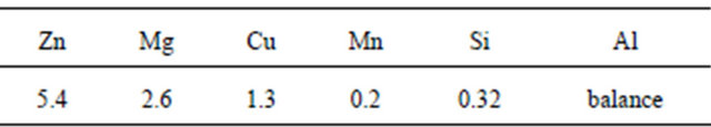
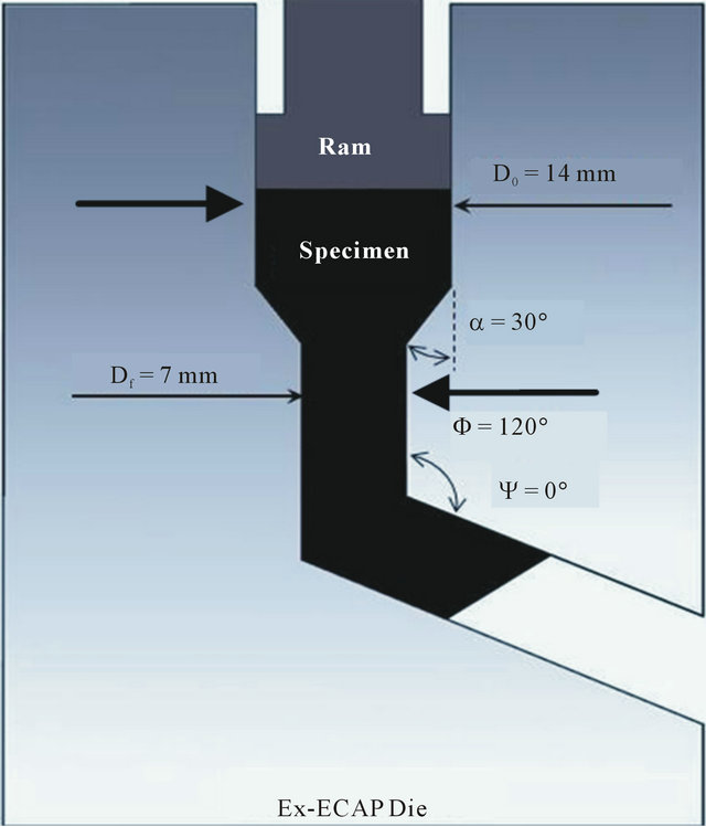
Figure 1. 2D view of integrated Extrusion-ECAP die.
extrusion is calculated as 1.38 (ε = 2ln (Df/D0)) without considering the effect of friction and assuming uniform deformation. Extruded material flows inside vertical channel and approaches to the intersection of two channels where ECAP step is executed. Intense shear deformation is imposed on sample during passing the ECAP region. Imposed plastic strain by one pass of ECAP is calculated by the expression proposed by Iwahashi et al. [17]:
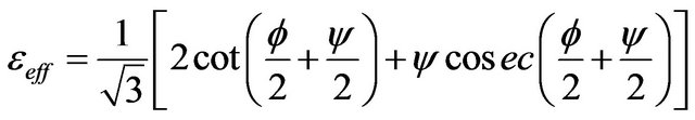 (1)
(1)
where  is die channel angle and
  is an outer curvature angle of two intersected channels. The die channel and outer curvature angles are 120˚ and 0˚, respectively. Therefore, the strain imposed during ECAP step is calculated about 0.8.
2.3. Finite Element Simulation
Deform 3DTM software was used for finite element investtigation of material flow and damage prediction during Ex-ECAP process. For this reason, die and punch were assumed as rigid parts due to higher strength and remaining undeformed during process. Only half of die, punch and sample were considered in the simulation because of the existence of mirror symmetry in the geometry of processing technique. Sample was assumed as deformable part and meshed with 45,000 tetrahedron elements with minimum size of 0.375 mm. Mechanical properties of Al7075 alloy were imported in the form of true stress-true strain curves at room temperature with different strain rates up to strain of 4. Figure 2 shows the true stress-true strain curves imported as a mechanical behavior of material. These stress-strain curves were obtained considering the Johnson-Cook plasticity model [18]. Also, the amount of friction coefficient between specimen and die channel wall is selected as 0.12 which is a typical value for deformation of aluminum alloys.
3. Results and Discussions
3.1. Material Flow
Figure 3 represents the material flow during different steps of FEM simulation of Ex-ECAP process. As it is seen, at step 38 (t = 1.5 s) extrusion has been carried out on front head of sample. At step 52 (t = 2.1 s), ECAP stage is executed on previously extruded part and material behind front head of sample is extruded and is in the second deformation step. At the end of process (step 100, t = 4 s), one part of specimen is subjected to two deformation steps by extrusion and ECAP. One part is only extruded, one part is in the extrusion zone, and the other has not been subjected to any deformation.
3.2. Strain and Strain Rate Distribution during Ex-ECAP
Figure 4 shows the variations of Von Misses equivalent strain and strain rate on symmetry plane of Ex-ECAPed sample. In Figure 4(a), it is observed that plastic strain is inhomogeneous in the inside of deformed sample. This inhomogeneity is related to the different amounts of deformation imposed on different regions and also the existence of friction between sample and die channel wall resulting in redundant shear deformation at near surface regions of sample. Processed sample can be divided to six regions (A to F). Strain rate is zero at most of the sample except extrusion and ECAP zones (B and D). It is
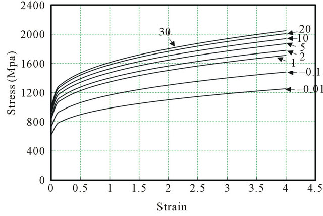
Figure 2. Stress-strain curves of Al7075 alloy at different strain rates obtained from Johnson-Cook data [17].
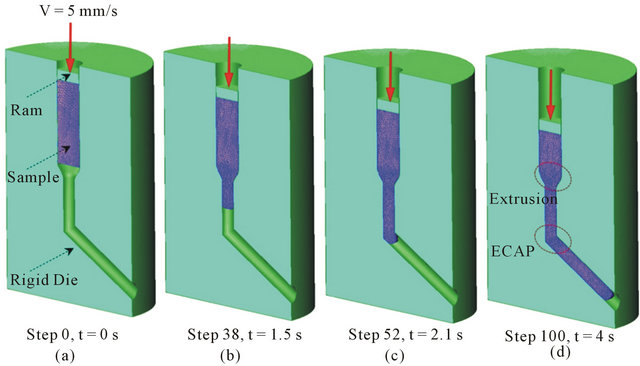
Figure 3. 3D view of material flow.
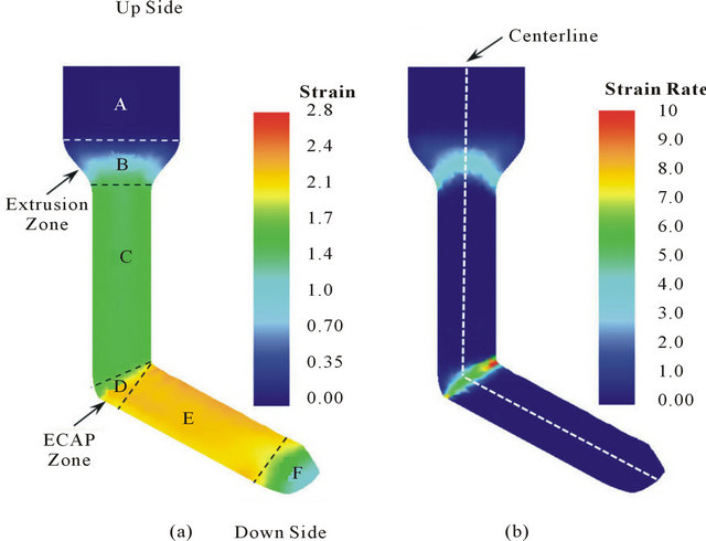
Figure 4. Equivalent plastic strain and strain rate distributions on symmetry plane of Ex-ECAPed sample.
worth noting that equivalent strain rate is none zero where deformation is imposed on sample. Then, the shape of regions with none zero strain rate indicates the shape of deformation zones. Figure 5 shows strain and strain rate distributions on centerline of Ex-ECAPed sample. At region (A), both strain and strain rate are zero. Therefore, part A is the unreformed portion of processed sample. Region (B) denotes the material in the extrusion zone. In this part, strain is increases gradually from zero to 1.5. However, strain rate is increases from zero to 4 and then decreases to zero again. It can be concluded that strain rate is not constant during extrusion step. Region (C) indicates extruded material with constant strain of about 1.5 and zero strain rates on centerline. Region (D)
denotes material passing the ECAP deformation zone. Therefore, strain is increases from 1.5 to 2.2 and strain rate is increases from zero to 6 s−1. Then strain rate decreases to zero at the end of deformation zone. Material in region (E) has been subjected to extrusion and ECAP passes successively with constant strain of 2.2 on centerline which is the sum of imposed strains during extrusion and ECAP steps.
3.3. Accumulation of Damage during Ex-ECAP
Different experimental investigations have been conducted on processing of difficult to work materials with ECAP [13]. The ability of these materials to process with SPD methods is considerably controlled by initiation of cracks started from top surface of samples. Croft Latham damage model can be employed successfully to evaluate the formability of materials during FEM simulation. The damage in Cockroft Latham model is calculated by using the following equation [19]:
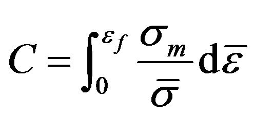 (2)
(2)
where σm is the maximum component of the tensile stress,  is effective strain,
  is effective stress, and C is a constant indicating the critical condition for initiation of fracture. According to Equation (2), fracture is occurred when the damage reaches to the critical value. It is clear that compressive stresses avoid the occurrence of cracking and tensile stresses encourage crack initiation. Figure 6 shows the progress of severe cracks at the ExECAPed sample on the top surface of region (E) (shown in Figure 4). These cracks are initiated from top surface of region (E) and propagated toward centerline of sample.
Figure 7 shows the predicted mean stress and Craft Latham damage factor distribution on the symmetry plane of deformed sample. As it is seen, damage factor and mean stress distribution are none uniform. Damage factor at regions (A - C) is zero and there are different amounts of damage at regions (D,C,F). It is also obvious from Figure 7(b) that the maximum damage is in the narrow area near the top surface of sample at region (C) which is in good agreement with experimentally observed cracks in the Ex-ECAPed sample in Figure 6. This area corresponds with domain of tensile mean stress as illustrated in Figure 7(a).
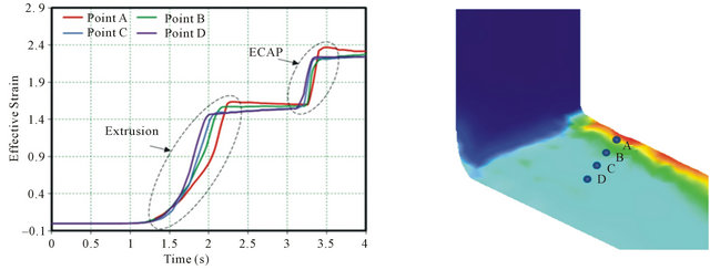
For detailed study on the nature of damage development during Ex-ECAP process, four nodes are selected across the region (E) from surface to center line of sample. As shown in Figure 8(a), plastic strain evolution with time has the same tendency at nodes A to D. Increasing of plastic strain is related to extrusion and ECAP steps. Variations of mean stress are also shown in Figure 8(b). As it is seen, stress is compressive at all nodes during extrusion step. From node D to A the value of compressive stress is increased. Damage is not developed during extrusion step as a result of compressive stress (Figures 8(b) and (c)). In contrast, mean stress is changed rapidly from compressive to tensile form during ECAP step. Also, the amount of tensile stress is increases from node D to A. Therefore, the amount of damage increases from node D to A as seen in Figure 8(c). Therefore, the results of FEM simulation confirm that both tensile stress and damage are increased from centerline to top surface of sample and cracking is occurred from top surface of sample just after second deformation step.
4. Conclusion
In the present study, Al7075 alloy was subjected to integrated extrusion-equal channel angular pressing at room temperature. During Ex-ECAP, cracks were found initiated from upper surface and propagated toward center-
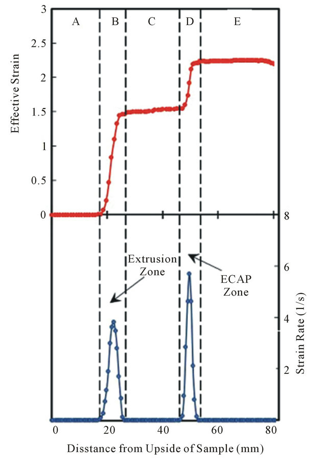
Figure 5. Equivalent plastic strain and strain rate distributions on centerline of Ex-ECAPed sample.
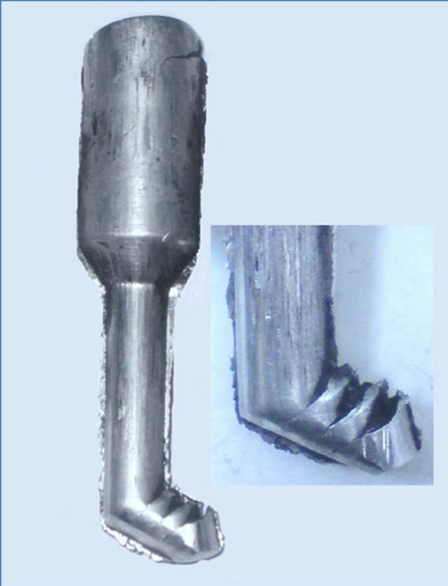
Figure 6. Development of cracks on the top surface of region (E) of Ex-ECAPed samples.
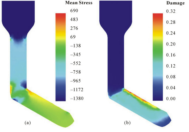
Figure 7. Mean stress (a); and damage (b) distributions on symmetry plane of Ex-ECAPed sample.
 (a)
(a)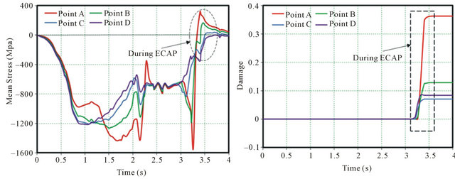 (b)
(b)
Figure 8. Evolutions of (a) strain; (b) mean stress; and (c) Croft Latham damage with time at selected node across the sample.
line of sample. Finite element results show that crack development is due to the change of stress from copression to tensile state during ECAP step. Also, the severity of the change in the amount of stress and consequently the Craft Latham damage increases from centerline to the near surface regions of sample. Therefore, damage is reached to the critical value at near surface regions and surface cracks are developed.
REFERENCES
- R. Z. Valieva, N. A. Enikeeva, M. Y. Murashkina, V. U. Kazykhanova and X. Sauvage, “On the Origin of the Extremely High Strength of Ultrafine-Grained Al Alloys Produced by Severe Plastic Deformation,” Scripta Materialia, Vol. 63, No. 9, 2010, pp. 949-952. doi:10.1016/j.scriptamat.2010.07.014
- M. Kawasaki, N. Balasubramanianb and T. G. Langdon, “Flow Mechanisms in Ultrafine-Grained Metals with an Emphasis on Superplasticity,” Materials Science and Engineering: A, Vol. 528, No. 21, 2011, pp. 6624-6629. doi:10.1016/j.msea.2011.05.005
- I. Charit and R. S. Mishra, “Low Temperature Superplasticity in a Friction-Stir-Processed Ultrafine Grained AlZn-Mg-Sc Alloy,” Acta Materialia Vol. 53, No. 15, 2005, pp. 4211-4223. doi:10.1016/j.actamat.2005.05.021
- K. J. Kurzydlowski, “Bulletin of the Polish Academy of Science,” Technical Sciences, Vol. 52, No. 4, 2004, pp. 301-311.
- A. Azushima, R. Kopp , A. Korhonen, D. Y. Yang , F. Micari, G. D. Lahoti, P. Groche, J. Yanagimoto, N. Tsuji, A. Rosochowski and A. Yanagida, “Severe Plastic Deformation (SPD) Processes for Metals,” CIRP AnnalsManufacturing Technology, Vol. 57, No. 2, 2008, pp. 716- 735. doi:10.1016/j.cirp.2008.09.005
- R. Z. Valiev, Y. Estrin, Z. Horita, T. G. Langdon, M. J. Zehetbauer and Y. T. Zhu, “Producing Bulk UltrafineGrained Materials By Severe Plastic Deformation,” JOM, Vol. 58, No. 4, 2006, 33-39. doi:10.1007/s11837-006-0213-7
- S. M. Fatemi-Varzaneh and A. Zarei-Hanzaki, “Accumulative Back Extrusion (ABE) Processing as a Novel Bulk Deformation Method,” Materials Science and Engineering: A, Vol. 504, No. 1-2, 2009, pp. 104-106. doi:10.1016/j.msea.2008.10.027
- G. Faraji, M. M. Mashhadi and H. S. Kim, “Tubular Channel Angular Pressing (TCAP) as a Novel Severe Plastic Deformation Method for Cylindrical Tubes,” Materials Letters, Vol. 65, No. 19-20, 2011, pp. 3009-3012. doi:10.1016/j.matlet.2011.06.039
- Z. G. Fan, H. Jiang, X. G. Sun, J. Song, X. N. Zhang and C. Y. Xie, “Microstructures and Mechanical Deformation Behaviors of Ultrafine-Grained Commercial Pure (Grade 3) Ti Processed by Two-Step Severe Plastic Deformation,” Materials Science and Engineering: A, Vol. 527 No. 1-2, 2009, pp. 45-51. doi:10.1016/j.msea.2009.07.030
- Y. Estrin, M. Janecek, G. I. Raab, R. Z. Valiev and A. Zi, “Severe Plastic Deformation as a Means of Producing Ultra-Fine-Grained Net-Shaped Micro Electro-Mechanical Systems Parts,” Metallurgical and Materials Transactions A, Vol. 38, No. 9, 2007, pp. 1906-1909. doi:10.1007/s11661-007-9120-y
- B. Mania and M. H. Paydar, “Application of Forward Extrusion-Equal Channel Angular Pressing (FE-ECAP, in Fabrication of Aluminum Metal Matrix Composites,” Journal of Alloys and Compounds, Vol. 492, No. 1-2, 2010, pp. 116-121. doi:10.1016/j.jallcom.2009.11.098
- M. H. Paydara, M. Reihanianb, E. Bagherpoura, M. Sharifzadeha, M. Zarinejadc and T. A. Dean, “Consolidation of Al Particles through Forward Extrusion-Equal Channel Angular Pressing (FE-ECAP),” Materials Leters, Vol. 62, No. 17-18, 2008, pp. 3266-3268. doi:10.1016/j.matlet.2008.02.038
- F. Kang, J. T. Wang and Y. Penga, “Deformation and Fracture during Equal Channel Angular Pressing of AZ31 Magnesium Alloy,” Materials Science and Engineering: A, Vol. 487, No. 1-2, 2008, pp. 68-73. doi:10.1016/j.msea.2007.09.063
- N. Q. Chinha, J. Gubiczaa, T. Czeppec, J. Lendvaia, C. Xu, R. Z. Valievd and T. G. Langdon, “Developing a Strategy for the Processing of Age-Hardenable Alloys by ECAP at Room Temperature,” Materials Science and Engineering: A, Vol. 516, No. 1-2, 2009, pp. 248-252. doi:10.1016/j.msea.2009.03.049
- R. B. Figueiredo, P. R. Cetlin and T. G. Langdon, “The Processing of Difficult-to-Work Alloys by ECAP with an Emphasis on Magnesium Alloys,” Acta Materialia, Vol. 55, No. 14, 2007, pp. 4769-4779. doi:10.1016/j.actamat.2007.04.043
- R. B. Figueiredoa, P. R. Cetlinb and T. G. Langdon, “The Evolution of Damage in Perfect-Plastic and Strain Hardening Materials Processed by Equal-Channel Angular Pressing,” Materials Science and Engineering: A, Vol. 518, No. 1-2, 2009, pp. 124-131. doi:10.1016/j.msea.2009.04.007
- Y. Iwahashi, J. Wang, Z. Horita, M. Nemoto and T. G. Langdon, “Principle of Equal-Channel Angular Pressing for the Processing of Ultra-Fine Grained Materials,” Scripta Materialia, Vol. 35, No. 2, 1996, pp. 143-146. doi:10.1016/1359-6462(96)00107-8
- D. H. Li, Y. Yang, T. Xu, H. G. Zheng, Q. S. Zhu and Q. M. Zhang, “Observation of the Microstructure in the Adiabatic Shear Band of 7075 Aluminum Alloy,” Materials Science and Engineering: A, Vol. 527 , No. 15, 2010, pp. 3529-3535. doi:10.1016/j.msea.2010.02.024
- R. Luri, C. J. L. Pérez, D. Salcedo, I. Puertas, J. León, I. Pérez and J. P. Fuertes, “Evolution of Damage in AA- 5083 Processed by Equal Channel Angular Extrusion Using Different Die Geometries,” Journal of Materials Processing Technology, Vol. 211, No. 1, 2011, pp. 48-56.
NOTES
*Corresponding author.