Modern Mechanical Engineering
Vol.3 No.1(2013), Article ID:28254,5 pages DOI:10.4236/mme.2013.31004
Five Degree of Freedom Manipulator Motion Simulation Based on Virtual Environment
Tianjin University of Technology and Education, Tianjin, China
Email: 271632099@qq.com
Received November 18, 2012; revised December 19, 2012; accepted January 3, 2013
Keywords: Virtual Reality; Manipulator; EON Studio; Interactive Simulation
ABSTRACT
In order to achieve the five degree of freedom manipulator motion simulation based on virtual reality environments, the calculation of the manipulator motion path of the joint node, established the mathematical models and three dimensional models, completed five degree of freedom manipulator real-time interactive simulation study based on the EON Studio platform, finished the experimental simulation of mechanical arm motion path. Provide some theoretical basis for the multiple degrees of freedom, multi-channel input and multiple perception mechanical movement of virtual interactive simulation-based research in the EON environment.
1. Introduction
Virtual Reality Technology is an interdisciplinary technology, integrated the computer graphics, multimedia technology, artificial intelligence, computer network and sensor technology. And the Virtual simulation technology is one of the important applications of the virtual reality technology in CAD/CAM field. It is widely used in the mechanism design. The combination of virtual reality technology and machine reflects the new application of the digital age in modern industrial fields [1].
Mechanical arm is an important part of the industrial machine. It is a codependent motion mechanism consisting of shoulder, arm, wrist, body and walk mechanism. Currently, many CAD software, such as Pro-E, UG, solidworks, etc., they can not only complete a machine’s three dimensional modeling, but also do the mechanical movement simulation. But the movement simulation by these software have the defectiveness in real-time interactive performance. It’s meaningful to study the simulation of mechanical arms. Because it can lay the foundation for the further theoretical research, do some data detection based on realizing the theory research, reduce research cost and save time, etc.
2. Virtual Simulation Platform
Eon Studio is the software developed by the company of Eon Reality. It is a tool using graphical interfaces and used for researching and development the real-time 3D Multimedia applications. It is mainly applied in e-commerce, marketing, digital learning, education training and building space, etc. [2].
Eon Studio can be imput 3D model easily, combine with the three dimensional modelling software, and finish motion simulation through the interaction between the model tree and behavior module. Of course, it not only has the interactive movement node, but also support language programs as VBScript, Jscript, C++, etc. This software provides a platform for the good development of the complex movement.
3. The Robot Motion Mathematical Model
In fact, there are two types of kinematics research problems. One kind is called the forward kinematics problem, which solving the corresponding paw position and posture in the case of given the manipulator joint coordinate values. Another is called the inverse kinematics problem that calculating each joint rotation Angle of the manipulator when the position and posture of paw are given. During the Virtual motion simulation, firstly we should calculate the joint coordinate values of the mechanical arm according to the position and posture of the end of the hand, then achieve the aim by giving the coordinate values to each joint [3].
Set up the mathematical model of litchi picking mechanical arm in five freedom degrees. Shown as Figure 1:
Taking A, B, C, D, E as five coordinate systems of the mechanical arm, and the transformation matrix of the connecting rod is as follows:
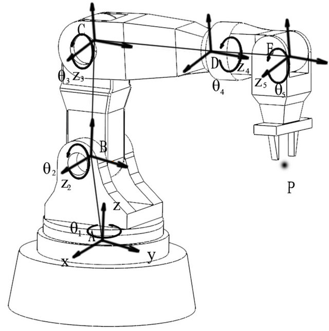

Figure 1. Mathematical model.
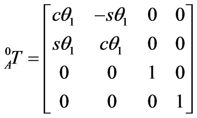

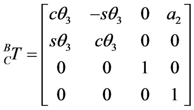
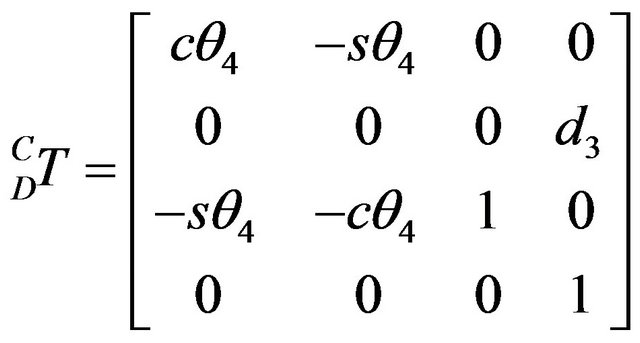

The manipulator’s transformation matrix through calculating the transformation matrix of each connecting rod:

When the position and posture of the connecting rod’s extreme are given:
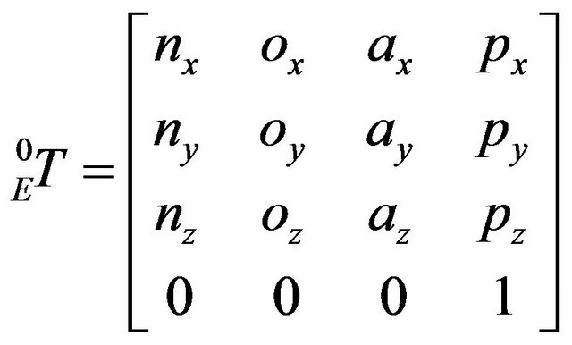
n, o, a and p are given.
Then we can get the numerical value of the 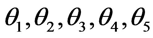 variables.
4. Mechanical Arm with Three Dimensional Digital Model
The motion arm in the type of hinge is also called joint type, axis type or humanoid type motion arm.
Virtual motion simulation is based on mathematical foundation as the theoretical basis, combining with the digitalization and visualization of the mechanical objects in real scene for real induction interaction. Therefore, different mechanical arms must adopt different threedimensional digital models to reflect the mechanical parts precision and authenticity. The three-dimensional modeling software can solve this problem efficiently. Here we use solidworks draw the part drawings of the mechanical arm, and complete the assembly drawing model. It is showed in the picture. But the file is not the file format required by the virtual interaction, so we need get the 3DS files through data conversion. The specific process is as shown in Figures 2 and 3:
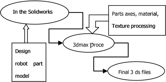
Figure 2. Three-dimensional digital model establishment process.
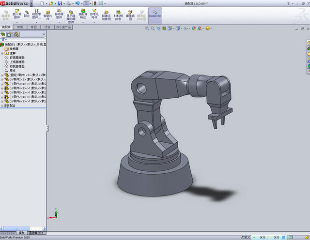
Figure 3. 3D model by solidworks.
5. Motion Simulation
5.1. Lead the Model
Lead the handled parts into the EON, and set the parameters and material. The coordinate system is the key in order to performance position and relative position of the objects completely in the three-dimensional space. Because different 3D software systems have different 3D coordinate expression modes. As the virtual development platform, EON has its own coordinate system .It is necessary to set each part Figure 2 Three-dimensional digital model establishment process coordinate system for realizing the simulation research of the virtual mechanical arm preferably and establish corresponding coordinate systems according to different mathematical models. Use the degree of freedom node (DOF) to determine various parts’ coordinates. Shown as Figure 4:
5.2. The Interactive Node’s Design
Based on the analysis of the mechanical parts can we know that the mechanical arm movement with many freedom degrees depending on moving and rotating. Firstly, through the matrix relations get the rotating and moving 3D vector of each coordinate nodes, then join the interactive node (input through the keyboard and mouse
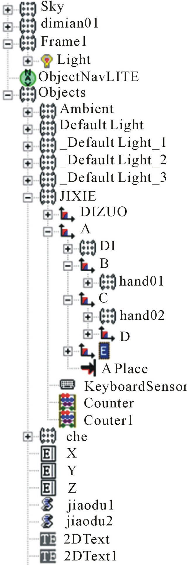
Figure 4. Each part coordinate in the DOF of EON.
primarily). Through inputting the end-effector coordinates relative to the mechanical arm origin, we can drive all mechanical parts movementing in 3D space to realize the whole mechanical arms’ movement. So, we get the interactive movement through the date from end arm drive the movement of the intermediate mechanical arm by the script calculation. The route relationship among the nodes is shown in the Figure 5, and the idea of the node design is shown in the Figure 6:
5.3. Motion Simulation
Based on the mathematical model of the mechanical arm with three freedom degrees, the movement between base and intermediate arm is relatively complex. So only through the script node can we complete the motion interaction. Part code is shown as follows:
Const Pi = 3.1415926 Const a1 = 0.0584 Const a2 = 0.11267462 sub On_IPosition()
p = IPosition x = p(0) − 0.0041 y = p(1) + 0.171 x1 = −x × 100 y1 = −y × 100 Result02 = 180/Pi × Atn(−y1/x1)
1) The Angle of the arm coordinates and the absolute coordinates:

Figure 5. Mechanical arm motion simulation routing relationship.
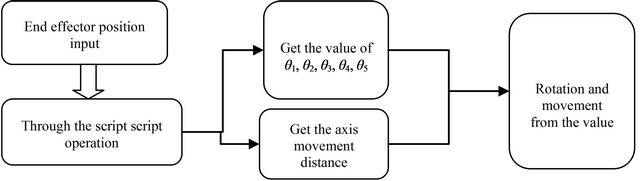
Figure 6. Node design idea.
M01 = Sqr (x × x + y × y)
2) The distance of the arm coordinates and the absolute coordinates:
T = (x × x + y × y − a1 × a1 − a2 × a2)/(2 × a1 × a2)
Q = (M01 × M01 + a1 × a1 − a2 × a2)/(2 × M01 × a1)
Result01 = 180/Pi × Acos(Q)
Bjiaodu = Result01 + Result02 − 90 3) The second bar’s rotation Angle:
Result03 = 180/Pi × Acos(T)
4) The first bar’s rotation Angle relative to the original Angle:
Cjiaodu = (Result01 + Result02 − Result03 − Atn(0.1126)) − 9 5) The second bar’s rotation Angle relative to the original Angle:
chart 1 Coordinate values of point B, C, D, E VxisC = eon.MakeSFVec3f(Cjiaodu,0,0)
VxisB = eon.MakeSFVec3f(Bjiaodu,0,0)
y2 = a1 × cos(Bjiaodu × pi/180) − 0.058 x2 = a1 × sin(Bjiaodu × Pi/180)
NPosition=eon.MakeSFVec3f(x2,y2,0)
end sub
5.4. The Simulation Experiment
The mechanical arm of virtual simulation mainly reflects the interactivity. Based on the EON interaction design, join the input devices as keyboard and mouse to complete the interactive simulation of 3D mechanical arm movement. As shown in Figure 7.
Receive B, C, E point coordinates of the mechanical arm shown in Table 1 and get B, C, E point motion paths through the drawing software shown in Figure 8.
6. Conclusion
With the industrial robots and the virtual reality technology continuously developing, the interaction motion simulation of the mechanical arm lays the foundation for further studying experimental detection, mechanical training, the virtual teaching and so on. Through the calculation of five degree of freedom manipulator motion path, to seek the mechanical arm of the shortest path is the path planning collision detection provides a theoreti-
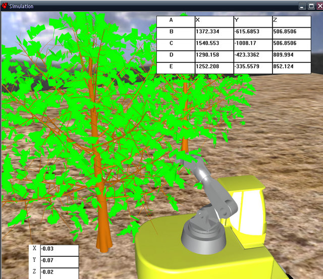
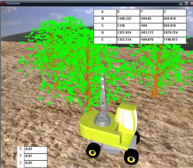
Figure 7. Interactive motion diagram of the mechanical arm EON environment.
cal basis. And mechanical arm motion simulation based on the EON virtual reality software with its real-time interactive provides research methods for seeking the shortest path of each node movement of the mechanical arm with many freedom degrees and the sports like the collision detection and obstacle avoidance in 3D scene.
Table 1. Coordinate values of point B, C, D, E.
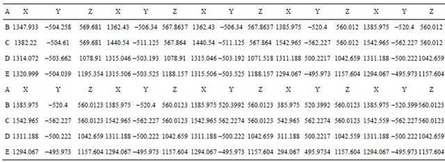
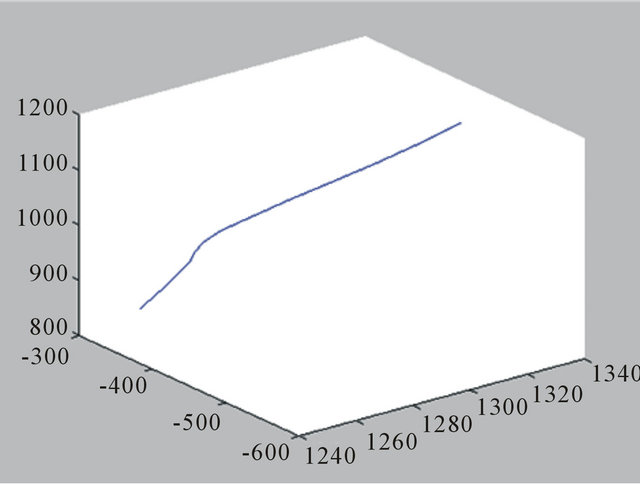
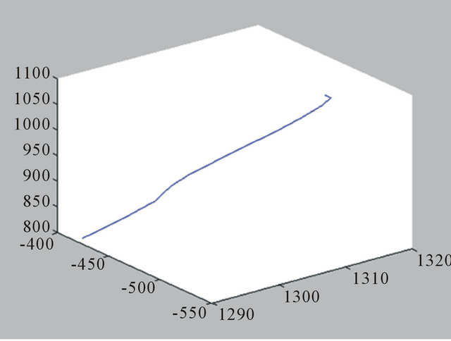

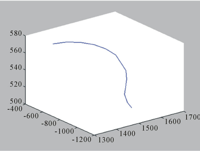
Figure 8. B, C, D, E point motion path.
At the same time, it also offers the research foundation to study the interactive simulation of mechanical motion with many freedom degrees and hardware inputs.
REFERENCES
- Q. J. Xie, G. Y. Liu and T. M. Ma, “Based on EON of Engine Motion Virtual Simulation Study,” Journal of Heilongjiang Bayi Agricultural University, Vol. 21, No. 3, 2009, pp. 84-86.
- Q. Q. Jiang, “Foreign VR Technology Development,” Winged Missiles Journal, No. 1, 2002, pp. 27-34.
- D. S. Sun and Y. Wang, “Robot Control Technology,” Mechanical Industry Press, Beijing, 1998, pp. 34-61.