Open Journal of Metal
Vol.2 No.3(2012), Article ID:22223,5 pages DOI:10.4236/ojmetal.2012.23011
Modeling Stress Intensity Factor of Rail Steel under Situation of Growing Fatigue Crack—A Novel Technique
Department of Instrumentation and Control Engineering, National Institute of Technology, Tiruchchirappalli, India
Email: upamanyu.nitt@gmail.com
Received June 28, 2012; revised July 31, 2012; accepted August 16, 2012
Keywords: Stress Intensity Factor; Acoustic Emission, Scattering; Rolling Contact Fatigue; Crack Growth
ABSTRACT
Simulation of stress intensity factor as function of rolling contact fatigue cracks of railway tracks and the vehicle load is made with the help of COMSOL Multi-physics software. It is found that the critical stress intensity factor i.e. 41.6 MPa·m1/2 is reached at a stress level of 32 MPa and at the crack size 1.15 × 10⁻² m. Noting the power law variation of acoustic emission count with increase in crack size (analogous to Paris Law), the simulation was further carried out to model the dependence of measured AE count with the stress intensity factor ahead of a growing RCF crack tip. It is demonstrated that AE measurement can be effective to trigger a control loop for avoidance of fatigue failure of railway track. In view of potential difference in the intensity of back scattered light from surface irregularities, a model is developed to find out the threshold intensity of scattered light that insures safety in the railway system against fatigue failure.
1. Introduction
In the present era of high speed, high axle load railway system, the derailment of trains is a major concern. Among the several probable, track related issues are recorded as responsible for majority of derailment mishaps across the world [1-3]. Railway track in between successive sleepers is similar to a simple supported beam, subjected to vehicle axle load. In fact the actual wheel load applied on the track while a train runs over it is given by the impact factor times the static axle load (P = φ Ps; φ is the impact factor greater than unity and Ps is the static axle load). Impact factor is however a function of train velocity. It is obvious that the bending stress situation over a section of railway track is quite complex due to a number of wheels passing over the region at time intervals and the consequential intermittent stress relaxation of the same. Nevertheless at any point on a track while a train passes over is cyclic in character. This leads to rolling contact fatigue (RCF) crack [4]. Certain RCF cracks branch down while propagation and are characteristically mode I driven cracks lying close to the rail’s transverse plane [5-7]. Since Stress intensity factor is a function of the length of the crack, its critical value for unstable crack growth corresponds to a critical RCF crack size under the present condition. In view of the predominance of failure due to abrupt growth of RCF cracks in railway tracks, attempts are made to simulate stress intensity factor under plane strain situation with the aid of COMSOL Multi-physics software.
In accordance with the principles of elastic plastic fracture mechanics, there is a critical magnitude of stress intensity factor ahead of the crack tip, (KIc for mode I loading) beyond which unstable crack growth sets in and causes premature material failure. Incidentally KIc is dependent on both the RCF crack size and the range of operating cyclic stress [8].
It appears that evolution of a control system as shown in Figure 1 requires the measurement of real time crack length at a place (over which the train is moving), its comparison with the simulated value of the allowable stress intensity factor and then sending the error signal to the above stated online control system which is capable of manipulating the train running parameters for avoidance of accidents. It is known that the growth of a crack
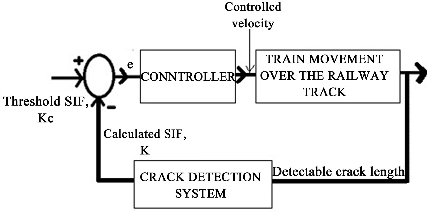
Figure 1. The proposed control loop to avoid derailment.
due to dynamic loading of a material is associated with the emission of elastic waves and that this is detectable by piezoelectric crystals [9]. Since such acoustic emission (AE) is a function of crack growth parameter, the present work has further attempted to find out the AE count, commensurate with the threshold crack size for unstable crack growth; but AE count measurement at a point in the railway track has to be made with the probe placed in the near vicinity of the growing crack. Thus if there is any spurious or extrinsic factor which comes up to cause unwarranted damage to the track in between the passage of two consecutive trains, AE technique will be proved inadequate to safe guard against such exigency. On the contrary, employment of principle of optical scattering is presumably quite effective in this regard as it may be used to sense the back scattered light from defects at reasonably large distance. However report on the design of any control system for health management of railway tracks with optical scattering as the aid for its condition monitoring is scarce in the existing literature. Hence attempt is made to develop a model of crack detection by means of measurement of the intensity of light back scattered from the defects on tracks at remote locations; this entails the scope for evolution of suitable design formalism of a control system for derailment prevention.
2. Computational Procedure
In COMSOL Multi-physics a particular rail section with crack formation over its surface is designed. Then crack propagation due to dynamic loading cycles is simulated. From this model we obtain the stress intensity factor (SIF). The Table 1 lists the dimensions used while designing the rail-track segment.
In the present investigation, the J-Integral method (which is a two-dimensional line integral, along a counterclockwise contour, Γ, surrounding the crack tip) is employed to find the stress intensity factor.
2.1. Rationale for AE Technique
As a principle, a component subjected to fatigue loading experiences its crack growth in accordance with ParisErdogan law [10]:

Table 1. Essential dimensions of rail track segment as used in the model.
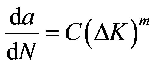 (1)
(1)
where ΔK is the change in the applied stress intensity factor commensurate with material property and stress situation,  is the crack length and N is the number of stress cycles; C and m are constants for a particular material.
Previous studies have developed an empirical relationship of AE count versus stress intensity factor which is found very similar in structure as the Paris-Erdogan law of crack propagation; this is expressed as [11,12],
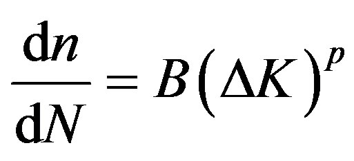 (2)
(2)
“n” is the AE count, “B” and p are constants.
This can be shown to lead to
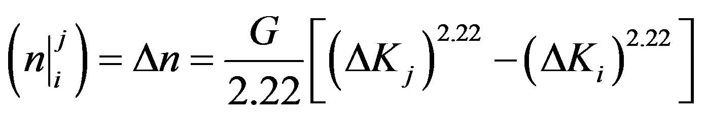 (3)
(3)
where, 
where 
The value of n, once known, can be used to find the stress intensity factor and consequently the crack length . Therefore the characteristic of AE counts associated with the fracture mechanics parameters can be used to provide damage evaluation of the material.
2.2. Rationale for Optical Scattering Technique
Previous experiments were conducted by the present author [13] by way of recording the images of the light wave scattered from the cracks of known length and width created on the polished surface of a real life rail section. With the help of rgb2gray command in the image processing tool box of MATLAB, the intensity indices for various crack dimension were obtained and finally a governing equation of the nature I = K1a2 + K2a + K3 where I represents the intensity index of the scattered light, “a”, the crack length and K1, K2 and K3 are constants with values −8.90 × 10⁴, 3.90 × 10³ and 21 respectively. Simulation in COMSOL Multi-physics was carried out to find the threshold value of measured intensity of scattered light that corresponds to the allowable stress intensity factor ahead of the moving crack. The alarming signal to the control system is proposed to be fed in the event the light intensity of scattered light from a region ahead of a running train reaches its limiting value as determined by the K value for crack growth instability.
2.3. COMSOL Simulation
Different models of similar structure but different crack lengths are developed using the Solid Mechanics module of COMSOL multi-physics software. This time, the sequence of steps used in modeling is:
1) Defining Global and Local parameters.
2) Drawing the rail 2D geometry using the CAD tools of COMSOL.
3) To set rail steel material’s properties in the rail domain.
4) To set the boundary conditions and introduce a boundary load for the rail domain.
5) To prescribe the direction of crack propagation due to the external boundary load.
6) To build a mesh comprising of free triangular elements. Again extra fine elements are provided near the crack tip for accurate solution by solver.
7) AE counts are obtained with the aid of Equations (2) and (3), and results are collected for post processing.
8) Light intensity is obtained by the use of the relationship given in equation.
3. Results and Discussions
The results of simulation describe the relationship between the stress intensity factor and the magnitude of applied stress for a specific crack length of 1.15 × 10⁻² m, Figure 2.
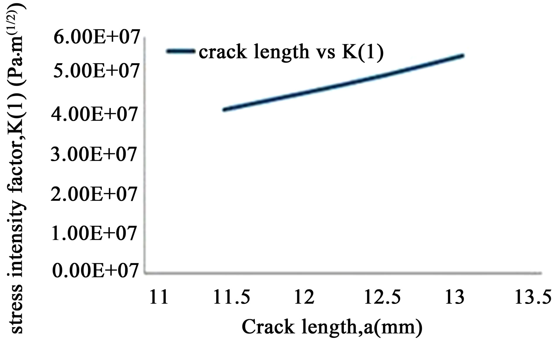
As seen in the Figure 2, the K value reaches 41.6 MPa·m1/2 for a stress value of 32 MPa. Since, the reported KIc of this rail steel is around 41 MPaٜ·m1/2, thus it is implied in the simulation results that the maximum permissible stress on the track would be 32 MPa and upon exceeding this, there will be catastrophic propagation of cracks and hence the accidental failure. At a maximum admissible stress value, 32 MPa (as the boundary load), the stress intensity factor ahead of the crack tip is found to increase with the increasing initial crack length, as shown in Figure 3.
The simulation provides us with a direct relationship between crack length and stress intensity factor. It therefore appears that, if a relation between the crack length and the corresponding acoustic emission count is developed, it will enable accurate prediction of structural integrity of the rail section just by the dynamic measurement of acoustic emission count emanated from any location of railway track. A representative output of such simulation work done in COMSOL is furnished in Figure 4. The AE count in correspondence with observed K value (hence with ΔK) is seen to be a function of crack parameter and loading situation.
Upon change in crack size (due to its growth, say) the magnitude of the pair of parameters (n and ΔK) will be altered. The nature of variation of AE count with crack length and the stress intensity factor is shown in Figure 5. It is evident from the figure that in either case, a power law variation of AE count with crack length or stress intensity factor is noted. Referring to Equation (1) one would find a parabolic relationship between crack length and stress intensity factor. Following this trend, the nature of variation of crack length or SIF with the corresponding AE count is positively inclined. The simulation output (as in Figure 4) enables to predict the probable failure of railway track with the help of measured AE count at any instant of time.
It may therefore be fairly reasoned that the in situ monitoring of AE count at any location of railway track
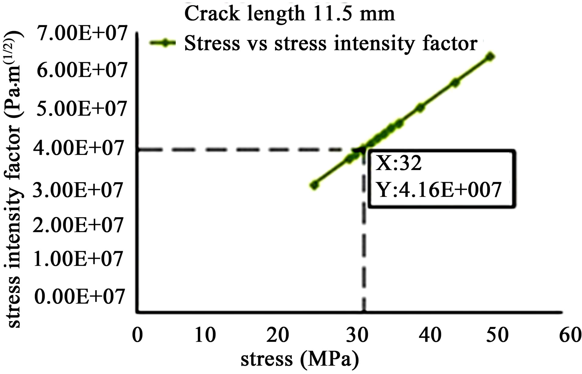
Figure 2. Relatioship between applied stress and stress intensity factor.
 (a)
(a)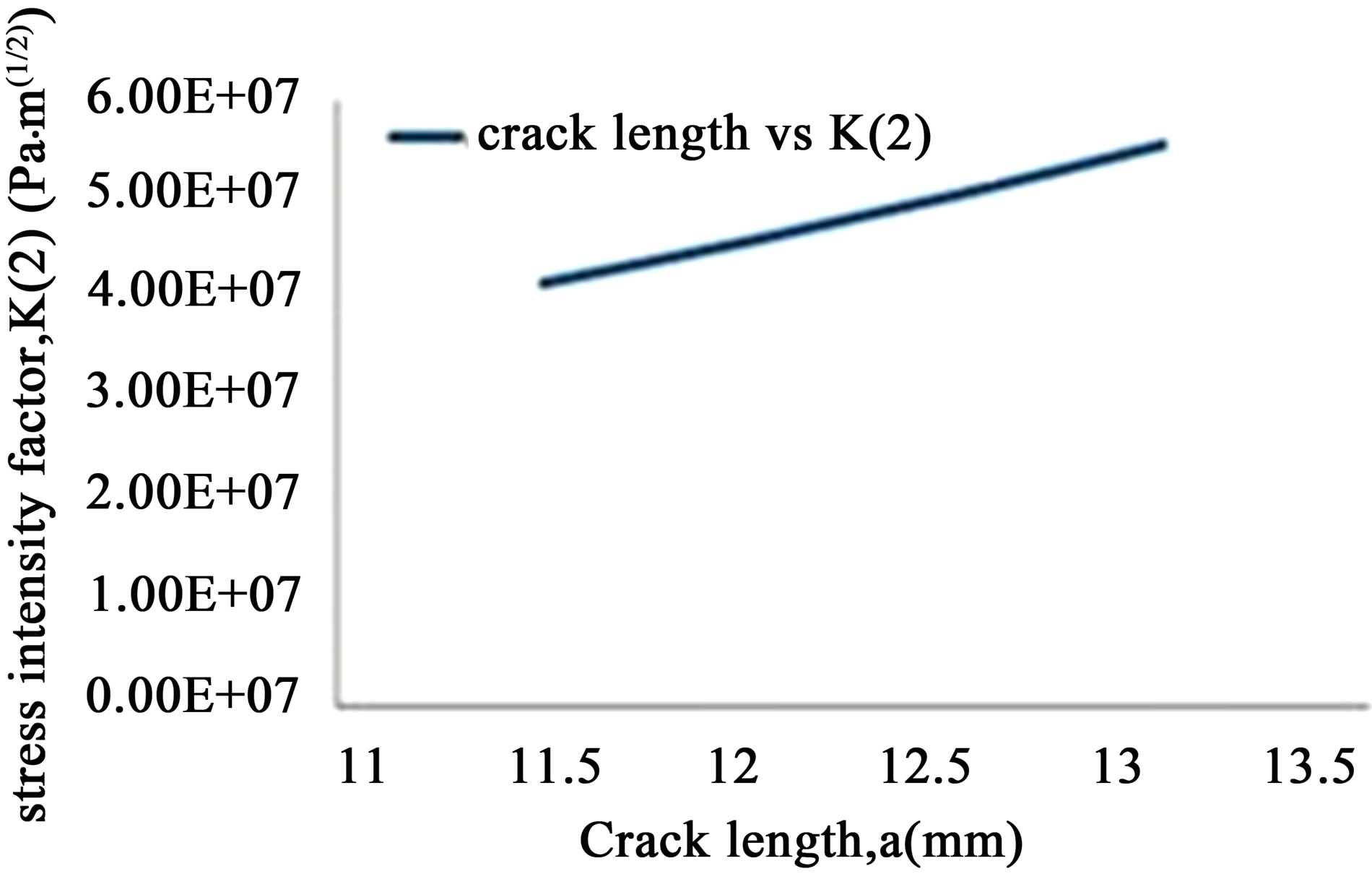 (b)
(b)
Figure 3. (a) Variation of stress intensity factor, K(1) with initial crack length (contour 1); (b) Variation of stress intensity factor, K(2) with initial crack length (contour 2).
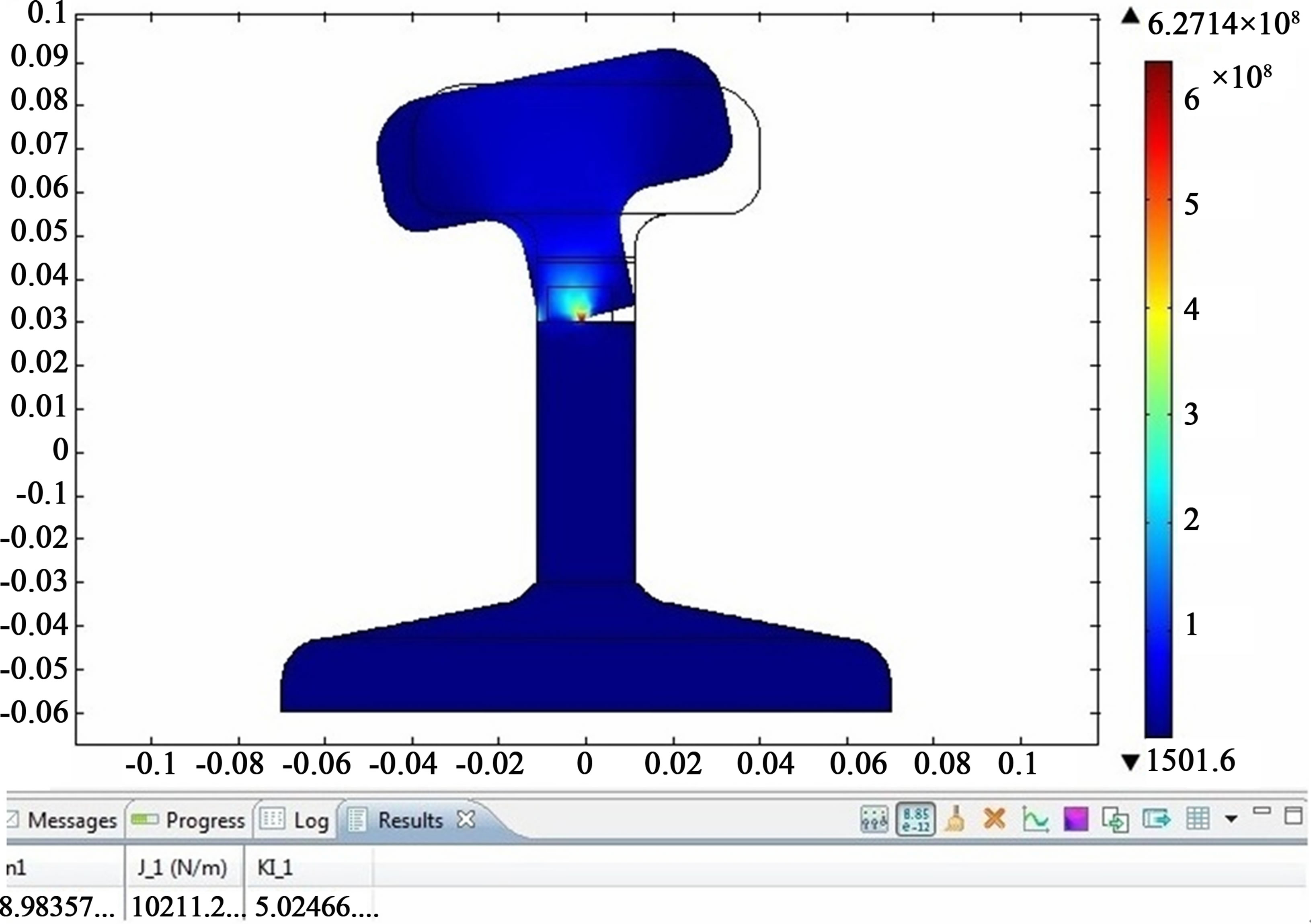
Figure 4. A representative output of simulation.
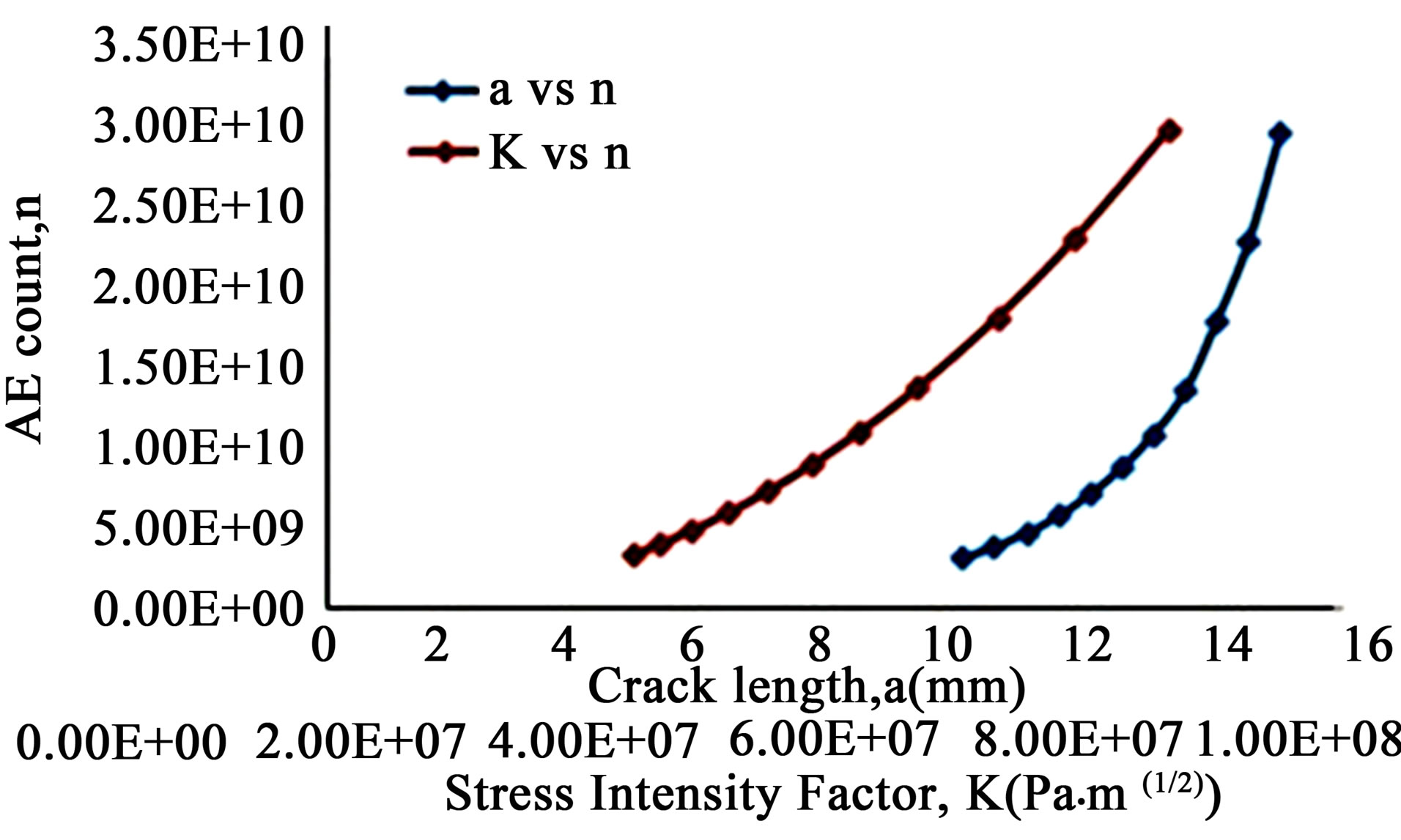
Figure 5. Relation between crack length and acoustic emission count.
at a particular time can be fed online to a control loop coupled with a decision support system.
When light is made to be incident on the discontinuities/cracks in a polished surface, it becomes scattered in all directions. The intensity of the scattered beam along a particular direction is dependent on a number of factors of which the size of the flaw (width at crack growth on the scattering surface) is extremely important. Again the width of the moving crack mouth is a function of its length. Since the length of a crack in a component fixes the stress intensity factor ahead of it under specific load situation, the magnitude of the intensity of back scattered light can be an effective measure of stress intensity factor. As KIc sets the limit of stable crack propagation, the proposed control system can effectively take care of the derailment issue if it is fed with the signal of scattered light intensity back scattered from a region ahead of a moving train. The results of simulation of scattered light intensity are shown in Figures 6 and 7. As seen earlier, the simulation result for stress intensity factor has already indicated that the stress intensity threshold, KIc (≈ 41.60 MPa·m1/2) is reached for a RCF crack length of 1.15 × 10⁴ m due to the concerned situation of cyclic bending stresses Figure 2. The variation of scattered
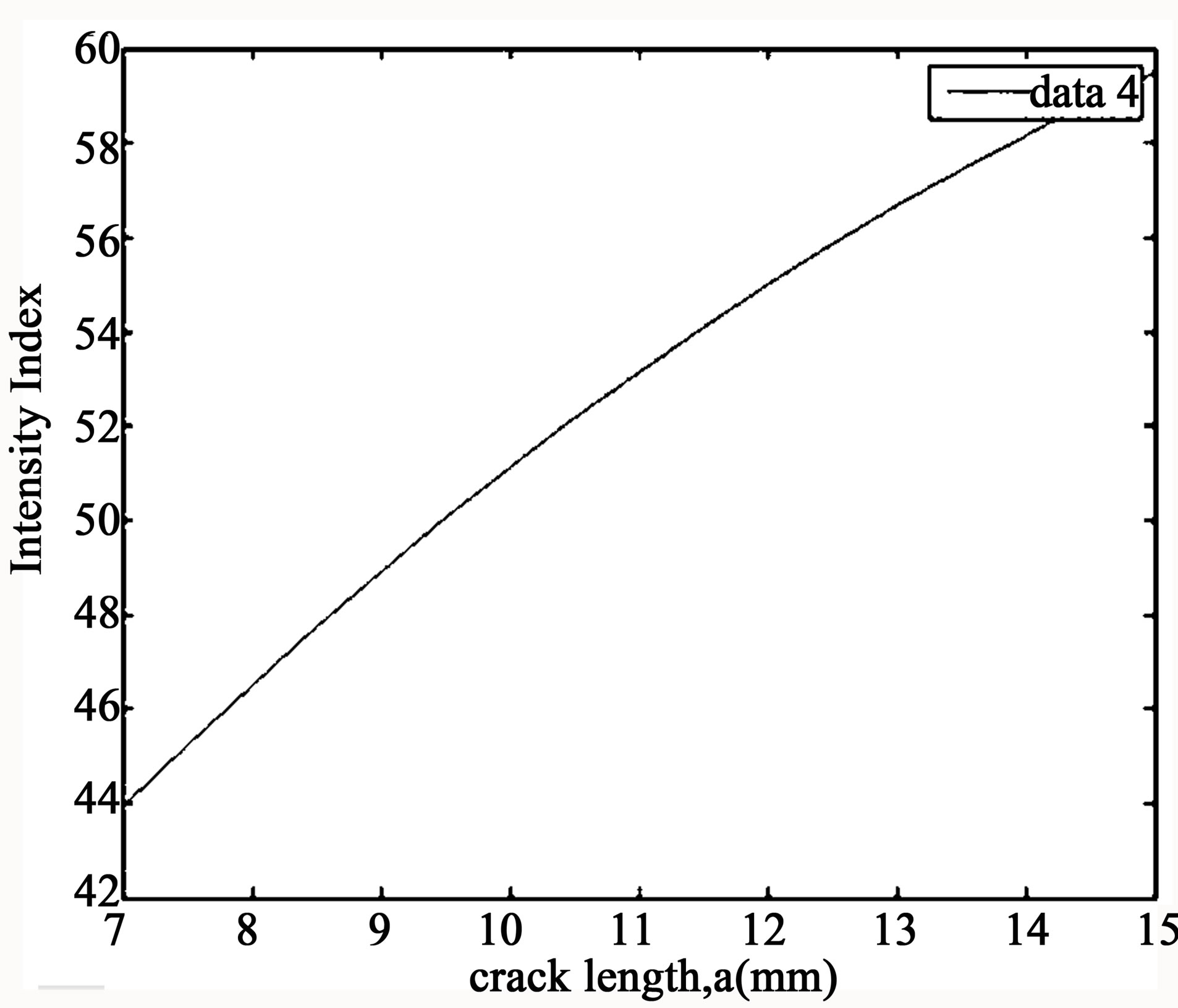
Figure 6. Scattering light intensity vs. RCF crack length.
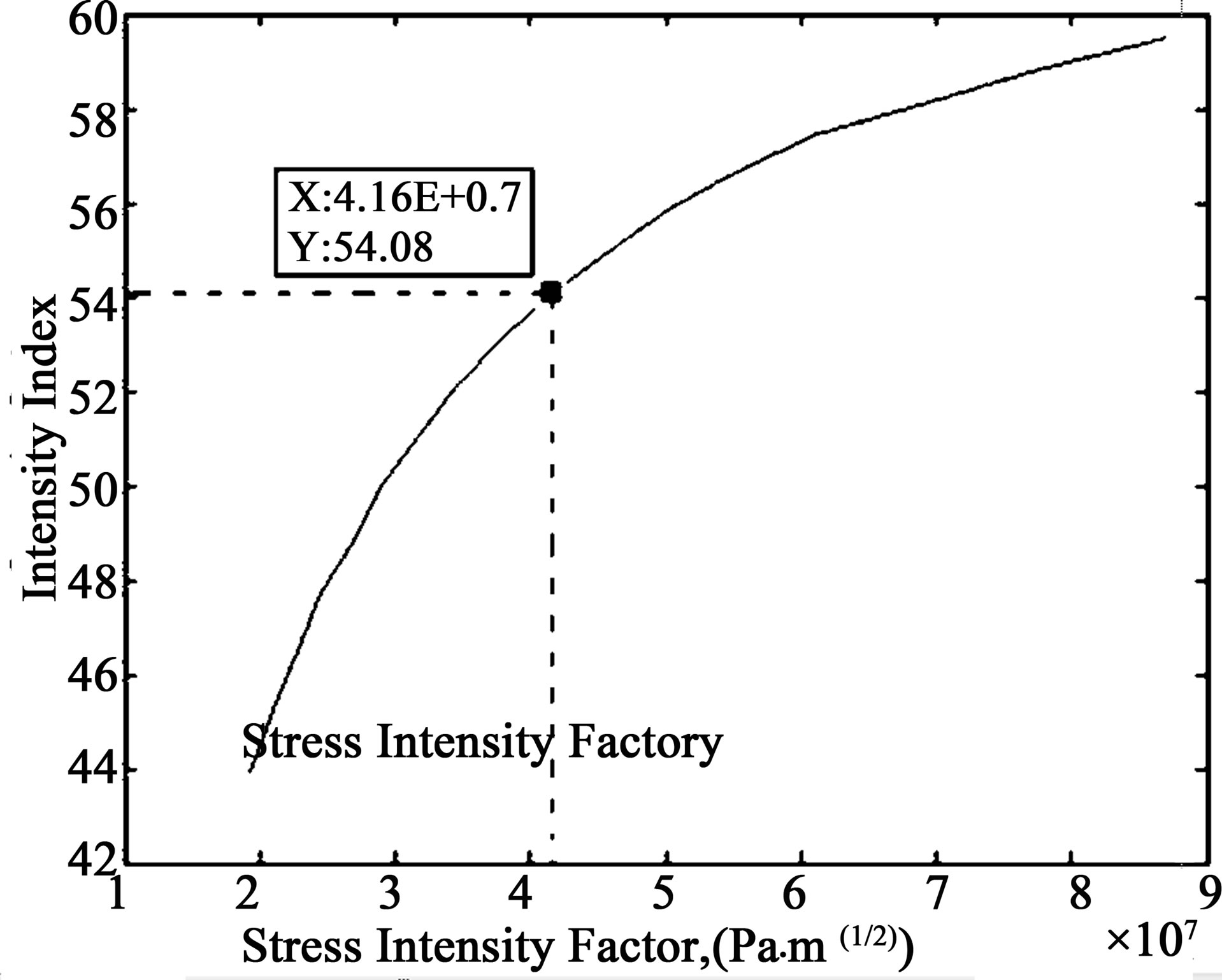
Figure 7. Variation of intensity of back scattered light with stress intensity factor.
light intensity with crack length (1.15 × 10⁴ m) bears a parabolic relationship Figure 6; it is clear from the figure that when the critical crack length (1.15 × 10⁴ m) is attained, the corresponding index for scattered light intensity becomes 54.07. This is corroborated by the results of Figure 7 which shows clearly that the critical stress intensity factor for the rail section (KIc ≈ 41.60 MPa·m1/2) corresponds to the detected light intensity index of 54.07. Thus a measured light intensity of index value 54.07 is an alarm for the onset of unstable crack propagation. This observation entails the possibility of insuring a safer railway practice. In consideration of a definite factor of safety an allowable maximum SIF can be designed; the corresponding simulated value of scattered light intensity index shall then be given to trigger the proposed control system and thus avert accidents.
4. Conclusions
The author wishes to conclude that the measurement of intensity of back scattered light from the irregularities of railway track is capable to describe the stress intensity factor. This novel technique of determining the stress intensity factor can be expended to design a control system thereby ensuring safety of railway systems by the avoidance of derailment mishaps.
5. Acknowledgements
The author wishes to acknowledge the support of received from the Head of the Department of Instrumentation and Control Engineering, National Institute of Technology, Tiruchirapally. Also a special thanks to Prof. M Umapathy for his support and expertise in the area of condition monitoring.
REFERENCES
- G. Chattopadhyay, D. Raman and M. R. Alam, “A Study of Derailment in Australia-Analyzing Risk Gap with Data Monitoring,” Proceedings of the 6th World Congress on Engineering Asset Management, Springer, Duke Energy Center, Cincinatti, 3 October 2011, p. 104.
- R. J. Greene, J. R. Yates and E. A. Patterson, “Rail Crack Detection: An Infrared Approach to In-Service Track Monitoring,” Proceeding of SEM Annual Conference and Exposition on Experimental and Applied Mechanics, Saint Louis, 4-7 June 2006, pp. 741-748.
- R. J. Greene, J. R. Yates and E. A. Patterson, “In-Service Fatigue Crack Detection of Rail Using Thermal Techniques,” Proceeding of 9th International Conference on Fatigue, Atlanta, 14-19 May 2006, pp. 1-8.
- E. Magel, P. Sroba, K. Sawley and J. Kalousek, “Control of Rolling Contact Fatigue of Rails,” Proceedings of the ARAMA Annual Conference, Nashville, 19-22 September 2004, pp. 1-29.
- S. Mellings, J. Baynham and R. A. Adey, “Automatic Crack Growth Prediction in Rails with BEM,” Engineering Fracture Mechanics, Vol. 72, No. 2, 2005, pp. 309-318.
- H. A. Aglan and M. Fateh, “Fracture Damage Tolerance of Bainitic and Pearlitic Rail Steels,” International Journal of Damage Mechanics, Vol. 15, No. 4, 2006, pp. 393- 410. doi:10.1177/1056789506060775
- H. A. Aglan and M. Fateh, “Fracture and Fatigue Crack Growth Analysis of Rail Steels,” Journal of Mechanics of Materials and Structures, Mathematical Sciences Publishers, vol. 2, no. 2, 2007, pp. 335-346.
- G. E. Dieter, “Mechanical Metallurgy,” 3rd Edition, McGraw-Hill, New York, 1961.
- M. N. Bassim, S. St. Lawrence and C. D. Liu, “Detection of the Onset of Fatigue Crack Growth in Rail Steels Using Acoustic Emission,” Engineering Fracture Mechanics, vol. 47, No. 2, 1994, pp. 207-214. doi:10.1016/0013-7944(94)90221-6
- S. Tarafder, “Fracture Mechanics Concepts for Component Integrity Evaluation,” Proceedings of the Disscet ’98, BHU, Varanasi, 5-7 November 1998, pp 2-5.
- D. Fang and A. Berkovits, “Fatigue Design Model Based on Damage Mechanism Revealed by Acoustic Emission Measurements,” Journal of Engineering Materials and Technology, Vol. 117, No. 2, 1995, pp. 200-208.
- M. S. Zain, N. Jamaludin, Z. Sajuri, M. F. M. Yusof and Z. H. Hanafi, “Acoustic Emission Study of fatigue Crack Growth in Rail Track Material,” National Conference in Mechanical Engineering Research and Postgraduate Studies (2nd NCMER 2010), Kuantan, 3-4 December 2010, pp. 82-90.
- U. Banerjee, D. Bhadra, S. Dongre, A. Sinha and A. Sharma, “Modeling a Rail Crack Detection System,” B. Tech. Thesis, National Institute of Technology, Tiruchchirappalli, 2012 (Unpublished).