Open Journal of Composite Materials
Vol.09 No.02(2019), Article ID:91632,21 pages
10.4236/ojcm.2019.92006
Transverse Impact Response Analysis of Graphene Panels: Impact Limits
Muhammed Burak Sonmez, Hessam Ghasemnejad*, Hamad Kamran, Philip Webb
Centre for Structures, Assembly and Intelligent Automation, Cranfield University, Cranfield, UK

Copyright © 2019 by author(s) and Scientific Research Publishing Inc.
This work is licensed under the Creative Commons Attribution International License (CC BY 4.0).
http://creativecommons.org/licenses/by/4.0/


Received: February 19, 2019; Accepted: April 5, 2019; Published: April 8, 2019
ABSTRACT
Explicit numerical studies were conducted to determine the transverse impact response of graphene panels. Although the mechanical properties of graphene are well documented in both quasi-static and dynamic conditions via nano- and microscopic studies, the impact behaviour of the material at the macroscale has not yet been studied and would provide interesting and crucial insight in to the performance of the material on a more widely recognizable scale. Firstly, a numerical impact model was validated against an analytical impact model based on continuum mechanics which showed good correlation between contact-force histories. The performance of graphene panels subjected to impact was compared to the performance of panels composed of aerospace-grade aluminium and carbon fiber reinforced polymer (CFRP) composite. The graphene panel was found to exhibit lower specific energy than aluminium and CFRP at the low-energy range due to its inherently superior stiffness and intrinsic strength. On the other hand, the ballistic limit of 3 mm thick graphene panels was found to be 3375 m/s, resulting in an impact resistance 100 times greater than for aluminium or CFRP, making graphene the most suitable material for high-velocity impact protection.
Keywords:
Graphene, Ballistic, Impact, CFRP

1. Introduction
Graphene is a two-dimensional allotrope of carbon with a hexagonal honeycomb nanostructure at such a minute scale that magnification of 280 million times is required for visualisation [1] . Freestanding monolayer graphene was first discovered in 2004 by Andre Geim and Konstantin Novoselov [2] , research for which they were awarded the Nobel Prize in Physics in 2010. Since its discovery, there has been huge interest in this new material, with a year on year increase in research investments and publications [3] , leading to quantification of its unique properties.
Graphene is the thinnest and strongest material ever measured [4] , and its in-plane carbon bond is stronger than the tetrahedral one found in diamond. Additionally, it is extremely flexible and has the ability to stretch to 20% of its original state [5] . Furthermore, it has high thermal conductivity [6] and intrinsic mobility [7] , higher than that of copper and silicon, respectively. Finally, it is transparent [8] and impermeable to even the smallest gaseous particles [9] . Due to its extraordinary properties, researchers have found applications for graphene in many fields such as biomedicine [10] , solar energy [11] , sensors [12] , superconductors [13] , and structural nanofillers [14] , and it is predicted to affect many more fields in the near future. Unfortunately, there is an overbearing problem in applying graphene to these fields due to the lack of implementation and preparation at a high standard and volume, as concluded in a detailed review by Mohan et al. [3] .
So far, there have been only a handful of studies conducted on the impact response of graphene. In 2014, Lee et al. [15] were the first to demonstrate its energy absorption capabilities. They used their advanced laser-induced projectile impact test to project a spherical silica impactor (microbullet) at high speeds towards multilayer graphene specimens with thicknesses ranging from 10 to 100 nanometres―30 to 300 layers of graphene sheets. The graphene specimens tested were produced using high-standard mechanical exfoliation with an effective lateral dimension of 85 micrometres.
Due to the ability of graphene to delocalise the stress caused by impact, it was found that the penetration energy of their multilayer graphene specimens was comparatively 8 to 12 times higher than that of steel. This they attributed to the ductility of the material where a relatively wide penetration hole is produced during impact. They also found that material not in the vicinity of the impact area absorbs kinetic energy from the impactor, but this results in high dynamic tensile stresses. Hence, the impactor experiences a much higher contact area during impact, more than any other material at such high impact velocities. They concluded that their impact study revealed extremely high speed of sound for graphene, which was the reason why delocalisation of the concentrated stresses was so efficient. Additionally, the material displayed high strength and stiffness, and a relatively anisotropic structure, confirming findings from previous research on the material’s mechanical properties.
The experimental impact analysis by Lee et al. was followed by a number of numerical and analytical studies. Seifoori et al. [16] studied the transverse impact behaviour of a graphene sheet using molecular dynamics (MD) simulations alongside finite element method (FEM) simulations and compared results against an analytical model of a spring-mass system. The analytical and numerical models are all illustrated in Figure 1 on the following page―the results for
 (a)
(a)
 (b)
(b)
 (c)
(c)
Figure 1. (a) Schematic of analytical model, (b) View of molecular dynamics impact simulation showing deflection, (c) View of FEM impact model showing deflection [16] .
all three models were found to match in terms of panel deflection. They found that for relatively small impactor masses, the boundary conditions do not affect the results, and the impacted panel does not need to have finite dimensions. It was also successfully shown that deformation of the impactor would decrease maximum deflection, as energy is partially absorbed by the impactor’s local deformation. Finally, they concluded that an increase in striker velocity results in an increase in the maximum deflection until fracture occurs. Similar findings were reported a year later by Yoon et al. [17] .
Most recently, Bizao et al. [18] found that several numerical and experimental papers in the past had significantly different results, especially in terms of the specific energy absorption of graphene specimens with differing numbers of layers (single-layer or multilayer). They used a molecular dynamics approach to define a scaling law to accurately determine the effect of the number of layers of graphene on energy absorption, and found excellent agreement between experimental and numerical results, thus showing the importance of scaling.
Another study conducted in the same year [19] looked at the failure mechanisms due to ballistic impact on multilayer graphene models of up to 25 layers. They found that a combination of failure modes occurs, akin to CFRP composite failure. The top layers of the panel were found to undergo local failure by fragmentation or plugging, whereas for bottom layers it was the opposite, with global failure due to formation of petals. They also quantified the effect of impactor shape by comparing cylindrical and spherical impactors. Above a certain number of layers of graphene (10 - 15 layers), the cylindrical impactor was capable of penetration at lower velocities.
Recently, many analytical studies have resulted from this experimental and numerical research on the impact response of graphene. This was due to the inability of previous analytical models to consider the non-local vibrations for each vibrational mode. Hosseini-Hashemi et al. [20] used non-local theory of elasticity to derive the equations of motions for impact on a single-layer graphene sheet; they also incorporated classical plate theory in to their studies, which meant assuming that the graphene sheet was a thin panel. They also derived a contact law to define the force acting between the panel and impactor, similar to previous approaches; namely approximating the mathematical function for van der Waals forces. Even though there were many differences and assumptions made in their analytical model, the impact response results were in agreement with molecular dynamics simulations.
From this review of the state-of-the-art for graphene, one can see the lack of studies conducted on the macroscale; the scale at which the subject is clearly visible to the naked eye. The many research papers documenting the mechanical performance of pure graphene, whether it is single-layer or multilayer, have been solely focussed on graphene at the nano- or microscale. Even though the material cannot be produced to the required dimensions, global research efforts on graphene are indicating that we will reach this goal in the next twenty years. Thus, it is vital to determine the structural response of macroscale graphene.
This paper involves dynamic mechanical analysis of impact on macroscale pure graphene panels via numerical means. Its performance is contrasted against aluminium and CFRP panels for a range of impact energies. Analyses are conducted by employing dynamic explicit solvers ABAQUS and Ls-Dyna, alongside the multi-paradigm computing environment in MATLAB.
2. Analytical Impact Model of Graphene
In this section, the analytical impact model for graphene is discussed. In previously published research [15] - [20] , graphene has never been analytically modelled at the macroscale. As theseanalyses were based on nano-indentation, scaling is not possible as the contact-force history is a function of the two-dimensional Young’s modulus . Therefore, another method is applied to an elastic graphene material model to validate the numerical model of graphene for use in studies following this section. The theoretical formulations for the analytical model were originally proposed by Whitney and Pagano [21] and were also described by Whitney [22] using first order shear deformation theory. As opposed to composite materials, the graphene material is assumed to be isotropic, as previous research [15] [23] has indicated only a marginal difference between the longitudinal and transverse Young’s moduli. The material properties are summarised in the following section. All other parameters and assumptions still apply to the graphene model as in the composite model: Hooke’s law, constant thickness throughout panel, ignoring body forces, overall geometries of panel and impactor, and simply supported panel edges. Comparison between analytical and numerical results is presented in Figure 2 on the following page.
3. Explicit Numerical Analysis of Graphene Panel
The material properties that represent graphene are summarised in Table 1. The Poisson’s ratio of graphene was taken from Mohiuddin et al. [24] and is a widely agreed-upon value [4] . The density of graphene is also valid as shown in the work of Stankovich et al. [25] and Lee et al. [15] .

Figure 2. Contact-force history comparison between analytical and numerical models for graphene.

Table 1. Elastic material properties of graphene.
The numerical model of the impactor and panel is modelled in ABAQUS explicit. The panel is modelled as a continuum shell with reduced integration (SC8R), simply supported edges, and dimensions equal to 150 × 150 × 1 mm3. Interaction properties assigned between the surfaces of the impactor and panel are tangential and normal in behaviour. The tangential behaviour is frictionless, whereas the normal behaviour includes a specified contact stiffness equal to 4.39 × 10¹⁰ N/m. The impactor is modelled as a 3-D deformable solid with reduced integration (C3D8R) and 70 mm diameter. Finally, a predefined velocity field is used to input the impact velocity.
An impact energy of 10 J is applied to the impactor in the analytical and numerical models of impact on a graphene panel, resulting in an impact velocity of 3.8 m/s. It can be seen in Figure 2 that there is a good agreement between the contact-force histories. The error was larger in the contact duration than in the peak contact force. The contact duration is 14% longer in the numerical model, and the peak contact force is 2% lower in the analytical model. It can be seen that the analytical model is stiffer than the numerical model due to the shorter contact duration. The difference in global stiffness is due to the inherent difference in complexity between the two models. However, for the relatively low errors, especially with peak contact force, the simplicity of the analytical model is favoured to more complex models which otherwise could predict the contact-history more accurately.
The analytical models of impact on graphene panels over-predict the global stiffness, resulting in shorter contact times. However, graphene is stiffer than CFRP, as graphene was found to produce higher peak contact forces and lower contact duration times. Results were found to be 5.3 ms contact duration and 3.4 kN peak contact force for the CFRP panel, and 3.6 ms and 5.3 kN for the graphene panel. Also, the maximum deflection of the graphene panel was 2.5 mm, as shown by Figure 3, which is almost half that of a CFRP panel, showcasing the difference in material stiffness. Finally, since the analytical model of graphene has provided a contact-force history that correlates well with the numerical model, the numerical model is deemed valid.
4. Impact Behaviour of Graphene vs CFRP and Aluminium
The performance in impact of graphene at the macroscale is very limited in literature. Its static mechanical properties have only ever been hypothetically determined where a 1 m2 single-layer graphene sheet is supposedly able to support a 4 kg mass [26] . This section details the research conducted to numerically analyse the impact characteristics of a thin graphene panel, and then compare its performance to aluminium and CFRP.
4.1. Graphene Model
The choice of method for modelling the graphene panel for impact is governed by its mechanical properties available in the published literature. Research that determined anisotropic properties of the material, such as Ni et al. [23] and Lee et al. [15] , has not yet conducted the required testing to determine the various plasticity and failure parameters required to model the material in an anisotropic manner, such as those required by Hashin damage criteria in explicit solvers. Therefore, isotropy is assumed for the graphene panel.
An identical relationship is also found in other research, such as that illustrated in the appendix section of Yoon et al.’s work [17] . Therefore, the elastic model used in the previous section here is transferred to LS-Dyna, importing its elastic properties. Furthermore, results from literature indicate the minimal strain-rate dependency of graphene, and thus, the material model is made independent of strain rate effects. Figure 4 shows the original stress-strain relationship found in Ni et al. [23] , and also the simplified relationship for use in LS-Dyna, where the elastic region, plastic region, and point of failure are highlighted. Note the assumption is that the graphene model is only considered in longitudinal mode, and thus, the stress-strain relationship for the longitudinal mode is used for material modelling, whilst the transverse alternative is ignored.
From this plot, we can see that the failure strength of graphene is 202 GPa, and failure strain is 0.404. The panel is modelled in LS-Dyna using a standard shell section with default formulations, and it has a geometry of 150 × 150 × 3 mm with five integration points through its thickness. The steel impactor is modelled as a solid section with a rigid material model (MAT20). Also, the impactorhas sphericalgeometry with a diameter of 25 mm. The edges of the panel are simply supported and contact is defined using Nodes to Surface conditioning where the nodes of the panel (slave) are functionalised for contact with the impactor’s surface (master). By default, failure occurs in the numerical model by deletion of elements once the failure strain is reached by a particular element. This failure definition is overridden by the Tied Nodes Failure constraint, which results in a shell model for the panel where adjacent elements do not have merged nodes at common locations as is usual. The Tied Nodes Failure constraint effectively connects common nodes of shell elements, allowing for realistic rupturing along the sides of these elements once the failure strain is reached. The equivalent plastic failure strain as used for this definition is shown in Table 2.
Table 2. Mechanical properties of graphene for Piecewise Linear Plasticity material model. is the equivalent plastic strain at which failure initiates.

Figure 3. Deflection results of numerical model showing point at which maximum deflection occurs, with a value of 2.5 mm for the centre of the graphene panel.

Figure 4. Stress-strain relationship of graphene with data from Ni et al. [23] , and simplified relationship for piecewise linear plasticity model (MAT24) in LS-Dyna. Elasticity is indicated by the green region, with a Young’s modulus of 764 GPa; plasticity is shown in blue; and the red region is the area in which failure occurs.
4.2. CFRP Model
To provide an accurate comparison for graphene, a composite model with progressive failure including in-ply failure and delamination is required. This is important because it enables the model to reflect the effect of interactions between the different failure modes and so provides a reliable method for global structural response to dynamic scenarios such as impact. Models based on continuum damage mechanics (CDM) are known to be the most accurate in predicting failure of composite panels [27] [28] . However, these studies have not considered delamination effects and have resulted in inaccurate representations of the composite panels.
Many research projects [29] [30] [31] have looked at incorporating delamination using cohesive zone modelling and found that it successfully represents delamination initiation and propagation. More specifically, delamination modelled by defining cohesive behaviour as an interaction property between adjacent surfaces is known to work successfully. Chen et al. [32] combined CDM with cohesive zone modelling to produce an accurate numerical model for simulating delamination, and damage initiation and propagation. Their methodology is used here to develop a numerical model of CFRP for comparison with graphene, the only difference being the use of cohesive contact as opposed to cohesive elements, in order to have a more computationally affordable model.
The panel has four individual continuum shell sub-laminates (SC8R) to represent each of the four sets of 6-layer plies. In other words, the first continuum shell sub-laminate has a 6-ply composite layup function applied to it with each ply angle equal to 0˚. The same method is then applied to the next three sub-laminates, with an altered ply angle to mirror the global layup (see Figure 5).
The geometry of the panel mirrors the graphene model with edge dimensions of 150 × 150 mm2 and a thickness of 3 mm. Since an individual ply is 0.125 mm thick, the thickness of each sub-laminate is 0.75 mm. The steel impactor is modelled as a rigid body (R3D4) with a diameter of 25 mm. Default tangential and normal interaction properties are globally assigned, with cohesive contact individually assigned to the three interfaces between each sub-laminate. The mechanical properties of CFRP and the properties relating to the Hashin damage model can be found in Table 3(a) and Table 3(b); s1t, s1c, etc. are the material strength parameters; G1t,c, G1c,c, etc. are the fracture toughness parameters each of which is related to an individual failure mechanism; η is the viscosity coefficient that is required to avoid convergence issues during simulation runs.
The delamination initiation and propagation parameters for cohesive contact are summarised in Table 4; Kz, Kzx and Kzy are the penalty stiffness coefficients that must be high enough to negate unwarranted elastic deformations in the interfaces between sub-laminates; σz is the out-of-plane normal strength; τxy and τzy are the in-plane shear strengths; GIc, GIIc and GIIIc are the mode I, II and III critical fracture toughness values acquired via experimentation and have exponential softening, with power-law based mixed mode behaviour laws applied, as discussed by Chen et al. [32] ; finally, the cohesive viscosity takes the same value as that of the Hashin damage model.
(a) (b)
Table 3. Mechanical and Hashin damage properties for CFRP from Chen et al. [32] .
Table 4. Cohesive behaviour and delamination damage initiation, evolution and stabilisation properties for CFRPfrom Chen et al. [32] .

Figure 5. Meshed numerical model for impact studies on CFRP panel showing the four individual sub-laminates, with total number of twelve integration points along the thickness, where layup from the top sub-laminate to the bottom is .
4.3. Aluminium Model
Johnson-Cook material model has been used extensively in the past for impact simulations as one of the most popular method for constitutively modelling of metals [33] [34] . Most recently, Sharma et al. [35] determined the Johnson-Cook material parameters for AA2014T652 aluminium alloy, which is used in many vital structural components in the aerospace industry. In their research, Sharma et al. were able to accurately predict the deformation behaviour of experiments. However, their axisymmetric model was found to underestimate the residual velocity. Therefore, as recommended, the axisymmetric approach is not adopted.
The Johnson-Cook model involves two expressions; one for plasticity and the other for failure. The first dictates the equivalent flow stress in terms of equivalent plastic strain, strain rate and temperature, as shown in Equation (1) below.
(1)
where A is assumed as the yield strength, B is the strain hardening coefficient, n is the strain hardening exponent, C is the strain rate sensitivity, and m is the thermal sensitivity, all of which were determined by Sharma et al. in their experimental studies. The second relationship required to complete the Johnson-Cook model is the cumulative damage model, which relies on the damage parameter:
(2)
where ∆ is the change in plastic strain and f is the strain at which fracture occurs. Failure occurs when the damage parameter reaches a value of one. Through experiment, the fracture strain has been made into a function:
(3)
σ* is the stress triaxiality, D1, D2 and D3 are damage parameters relating to the stress triaxiality, D4 is the damage parameter relating to strain rate, and D5 is that which is related to temperature. As temperature effects are ignored in this study, D5 = m = 0.
The aluminium panel is set up in ABAQUS explicit as a 3-D shell model (S4R) with five integration points along the thickness. Boundary conditions are simply supported, and panel dimensions are 150 × 150 × 3 mm. The impactor is modelled as a rigid steel sphere (R3D4) with diameter equal to 25 mm. Elastic material properties are taken from ESDU using an equivalent aluminium alloy, EN2089. These properties and those relating to the Johnson-Cook model can be found in Table 5.
The residual velocity of impact on the aluminium panel was analysed at different mesh densities in order to find the optimum design. The ideal mesh density matches that of graphene and CFRP, indicating that mesh convergence is dependent on geometry alone. The mesh density results in a total of 10,000 elements on the panel, with an individual element size of 1.5 mm. Although the simulation is independent of the rigid-body impactor’s mesh, it was meshed in this model with 2222 quadrilateral and 58 triangular elements.
4.4. Results and Discussion
Figure 6 and Figure 7 show the maximum deflections on the panels, clearly indicating that the graphene panel deflects far less than the CFRP and aluminium ones, and this is quantified in Figure 8, along with the peak contact force values.
(a) (b) (c)
Table 5. (a) Mechanical properties of AA2014-T652 from ESDU [36] , (b) Johnson-Cook plasticity parameters for flow-stress function [35] , (c) Damage parameters for Johnson-Cook fracture strain function [35] .

Figure 6. 20 J impact on (a) graphene, (b) CFRP and (c) aluminium panels.

Figure 7. 80 J impact on (a) graphene, (b) CFRP and (c) aluminium panels.
 (a)
(a)
 (b)
(b)
Figure 8. (a) Maximum deflection and (b) peak contact forces for the two impact energies.
Two methods are considered when analysing the energy absorbed by the panels. The first is more useful for instances when geometries must remain constant, such as in design of structural component (measured per unit volume; this does not require manipulation of raw energy data). The second involves the study of crashworthiness where the energy absorbed is analysed as a function of panel mass, resulting in a specific energy absorption (J/kg, requires division by panel mass, which varies amongst material densities). As mentioned in the previous parts of this section, the geometries of all three panels are identical at 150 × 150 × 3 mm3, indicating volumetric consistency.
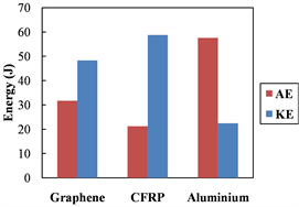
Furthermore, the energy absorption values are determined using three separate methods to ensure reliability. The first is via the difference in the initial and final kinetic energy of the impactor, the second is through an average of the summation of equilibrium internal and kinetic energies of the panel following impact, and the final is a summation of area under the force-displacement curves. The charts in Figure 9 show the general energy absorbed by each panel, and the final kinetic energy of the impactor. Following this, it can be seen that the aluminium panel absorbs the highest amount of energy per unit volume at these intermediate impact ranges, with an absorption proportion consistently over 50%. The reason for this is the large amount of plastic deformation present in the specimen as visualised in Figure 10. On the other hand, the CFRP model has been found to absorb less energy per unit volume due to its brittle nature, and tendency to delaminate at low stresses resulting in sudden loss in structural stiffness.
In respect of crashworthiness, the specific energy absorption of the results must also be analysed. By determining the mass of the graphene, CFRP and aluminium panels to be 149 grams, 89 grams and 189 grams, respectively, the specific energy absorptions (SEA’s) for each panel is determined, and then illustrated in Figure 11. For the 20 J impact, the CFRP panel is found to have the highest SEA, which is due to its lightweight nature, making it the most suitable material for this medium impact energy range. However, with the increased impact energy of 80 J, the CFRP panel is out-performed by the aluminium panel due to the superior ductility of aluminium and also the excessive damage in the CFRP panel. The damage in the CFRP panel is visualised in Figure 12, where tensile failure is almost reached in the matrix and fibres of the bottom sub-laminates, indicating that only a very small amount of absorption capability remains in the panel following this impact.
The main conclusion to draw from these results is the comparatively low energy absorption of graphene at these impact ranges. With a Young’s modulus that is six times greater in magnitude than CFRP composite, and ten times greater than aluminium 2014-T652, it was expected that the graphene panel would not deflect with the same magnitude as the other panels, and thus, would not absorb as much kinetic energy from impact. The factor that makes graphene so advantageous is its very high strength. The material’s Yield strength, at 69.9 GPa, far exceeds that of the aluminium, and its ultimate tensile strength of 202 GPa is ten times greater than that of the CFRP composite.
This means that the material is better suited to applications involving protection against extremely high impact energies. Figure 13 shows that the maximum stress in the panel during the 80 J impact remains in the elastic region with a value of 9.5 GPa in the centre of the panel, which is only 13.5% of the yield strength. Furthermore, it is important to acknowledge that with the introduction of graphene into structural design, the use of the terms low, medium and high in impact analysis become relative.
An additional point to consider when evaluating graphene against CFRP and aluminium, is the energy resistance of the materials, which is the impact-energy limit at which a material with a specific geometric configuration is able to withstand failure or penetration. For example, if one material has an energy resistance of x J, and another has 100x J, then the latter is said to be more energy resistant. Although graphene has poor impact absorption capabilities at the extremely low energy range, its superior energy resistance is yet to be quantified.
 (a)
(a)
 (b)
(b)
Figure 9. Panel absorbed energies (AE) and final impactor kinetic energies (KE) for (a) 20 J and (b) 80 J impact.

Figure 10. Equivalent plastic strain (PEEQ) on the aluminium panel following 80 J impact.
 (a)
(a)
 (b)
(b)
Figure 11. Specific energy absorption (SEA) results from (a) 20 J and (b) 80 J impact.

Figure 12. Damage evolution parameters for (a) fibre tension and (b) matrix tension through each of the four sub-laminates.

Figure 13. Von Mises stress output in LS-Dyna for graphene panel during 80 J impact.
5. Ballistic Limit Study
The final aspect of this paper determines the impact energy required to penetrate the graphene panel, formally referred to as the ballistic limit (V). The panel geometry tested in this section is identical to previous studies (150 × 150 × 3 mm3) and the impactor diameter is 25 mm. The final impact energy required for penetration of the 3 mm thick graphene panel is 364.5 kJ, which equates to a ballistic limit of V = 3375 m/s. The resultant impact resistance for graphene, CFRP and aluminium is illustrated by Figure 14 and Figure 15.
The aluminium panel from the previous section was found to have a ballistic limit of 105 m/s (see Figure 15). The result is compared to a paper published by Iqbal and Gupta [37] in which the ballistic limit of a similar high-strength Aluminium alloy of 3 mm thickness was found to be 108 m/s, showing good agreement with the numerical result. The same figure shows a ballistic limit of 107 m/s for a CFRP panel taken from the work of López-Puente et al. [38] . With ballistic limits of just over 100 m/s for the Aluminium and CFRP panels, these values are clearly minuscule in comparison to the graphene panel. In addition, when comparing the specific energy resistance (SER) of the three types of materials, a similar conclusion can be drawn, with the graphene panel exhibiting over 100 times the SER of aluminium (0.37 kJ) and CFRP (0.35 kJ).

Figure 14. Impact versus residual velocity for graphene panel.

Figure 15. Impact versus residual velocity for Aluminium and CFRP panels.
The manner in which failure occurs in the graphene panel is comparable to a recent experimental study on microscopic specimens of graphene by Lee et al. [15] , where the contact regions undergo high amounts of cone-shaped tensile stretching which then results in cracks propagating radially outwards extending beyond the area of impact. Figure 16 shows good correlation between numerical simulations from this section and experiments, where petals and the angle between radial cracks are highlighted. The impact on the graphene panel in LS-Dyna is shown in Figure 17, where the excessive, cone-shaped tensile stretching and the formation of petals are both visible.
6. Conclusions
A detailed analysis was conducted on the transverse impact response of graphene panels at the macro-scale using a combination of explicit finite element
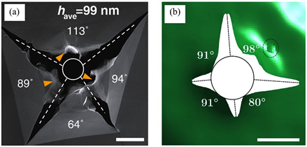
Figure 16. Penetration features of (a) 600 m/s impact on microscopic multi-layer graphene [15] and (b) 4000 m/s impact on macroscopic graphene panel with fragmentation highlighted by a dotted circle. Scale bars are (a) 5 µm and (b) 25 mm.

Figure 17. 4000 m/s impact on graphene panel in LS-Dyna with current impactor velocity at (a) 3260 m/s, (b) 2220 m/s, (c) 2190 m/s and (d) 2190 m/s.
(FE) solvers. Performance under low-energy impact of the graphene panel was contrasted to an aluminium and CFRP panel. Results found that the CFRP panel performed best on an SEA basis for a 20 J impact, but the aluminium outperformed the CFRP and graphene panels with an impact of 80 J. It was found that the graphene panel performs poorly as an energy absorber at low velocities due to its extremely high stiffness and yield strength. Following this, the ballistic limit of the graphene panel was found to be 3375 m/s. This is over 30 times higher in comparison to the aluminium and CFRP panels which had ballistic limits just over 100 m/s each, proving that graphene has an impact resistance far superior to any previously studied material.
In this paper, a number of limitations were encountered. The analytical model based on continuum mechanics is applicable only to low-energy impacts, as higher energies resulted in errors. Additionally, the model does not take plasticity or damage into account as delamination would almost certainly have occurred in the CFRP panel at the impact energies studied. Therefore, it is recommended to conduct analytical research using a damage-based model. Additionally, the LS-Dyna model of graphene was not stable below a thickness of 0.5 mm, and therefore, could not be compared to results available on micro- or nanoscale research.
In future work, it is recommended to focus on developing a more acceptable method of validation for modelling graphene at a macro-scale. However, as research is still largely focused on molecular-level analysis of the material, this promises to remain a difficult barrier to overcome in the near future. Other methods to expand the current work would be to analyse the effect of panel shape on impact resistance, and also to observe the response of the material to less dynamic scenarios such as buckling or compression-after-impact. Although there are many challenges, especially in manufacturing, this work demonstrates that graphene is potentially the most impact resistant material currently known at the macroscale, making it ideal for bulletproof vests, or protection against micro-debris impact in space.
Conflicts of Interest
The authors declare no conflicts of interest regarding the publication of this paper.
Cite this paper
Sonmez, M.B., Ghasemnejad, H., Kamran, H. and Webb, P. (2019) Transverse Impact Response Analysis of Graphene Panels: Impact Limit. Open Journal of Composite Materials, 9, 124-144. https://doi.org/10.4236/ojcm.2019.92006
References
- 1. Geim, A.K. and Novoselov, K.S. (2007) The Rise of Graphene. Nature Materials, 6, 183-191.
- 2. Novoselov, K.S., Geim, A.K., Morozov, S.V., et al. (2004) Electric Field Effect in Atomically Thin Carbon Films. Science, 306, 666-669.
- 3. Mohan, V.B., Lau, K.T., Hui, D. and Bhattacharyya, D. (2018) Graphene-Based Materials and Their Composites: A Review on Production, Applications and Product Limitations. Composites Part B: Engineering, 142, 200-220.
- 4. Lee, C., Wei, X., Kysar, J.W. and Hone, J. (2008) Measurement of the Elastic Properties and Intrinsic Strength of Monolayer Graphene. Science, 321, 385-388.
- 5. Ding, F., Ji, H.X., Chen, Y.H., et al. (2010) Stretchable Graphene: A Close Look at Fundamental Parameters through Biaxial Straining. Nano Letters, 10, 3453-3458.
- 6. Balandin, A.A., Ghosh, S., Bao, W.Z., et al. (2008) Superior Thermal Conductivity of Single-Layer Graphene. Nano Letters, 8, 902-907.
- 7. Novoselov, K.S., Geim, A.K., Morozov, S.V., et al. (2005) Two-Dimensional Gas of Massless Dirac Fermions in Graphene. Nature, 483, 197-200.
- 8. Sheehy, D.E. and Schmalian, J. (2009) Optical Transparency of Graphene as Determined by the Fine-Structure Constant. Physical Review B—Physical Review Journals, 80, 193411.
- 9. Yousefia, N., Gudarzi, M.M., Zheng, Q.B., et al. (2013) Highly Aligned, Ultralarge-Size Reduced Graphene Oxide/Polyurethane Nanocomposites: Mechanical Properties and Moisture Permeability. Composites Part A: Applied Science and Manufacturing, 49, 42-50. https://doi.org/10.1016/j.compositesa.2013.02.005
- 10. Pattnaik, S., Swain, K. and Lin, Z. (2016) Graphene and Graphene-Based Nanocomposites: Biomedical Applications and Biosafety. Journal of Materials Chemistry B, 4, 7813-7831.
- 11. Wang, X., Zhi, L. and Müllen, K. (2008) Transparent, Conductive Graphene Electrodes for Dye-Sensitized Solar Cells. Nano Letters, 8, 323-327.
- 12. Raju, A.P.A., et al. (2014) Wide-Area Strain Sensors Based upon Graphene-Polymer Composite Coatings Probed by Raman Spectroscopy. Advanced Functional Materials, 24, 2865-2874.
- 13. Brownson, D.A.C. and Banks, C.E. (2012) Fabricating Graphene Supercapacitors: Highlighting the Impact of Surfactants and Moieties. Chemical Communications, 48, 1425-1427.
- 14. Wu, Y., Chen, M., Chen, M., Ran, Z., Zhu, C. and Liao, H. (2017) The Reinforcing Effect of Polydopamine Functionalized Graphene Nanoplatelets on the Mechanical Properties of Epoxy Resins at Cryogenic Temperature. Polymer Testing, 58, 262-269.
- 15. Lee, J.H., Loya, P.E., Lou, J. and Thomas, E.L. (2014) Dynamic Mechanical Behavior of Multilayer Graphene via Supersonic Projectile Penetration. Science, 346, 1092-1096.
- 16. Seifoori, S. and Hajabdollahi, H. (2015) Impact Behavior of Single-Layered Graphene Sheets Based on Analytical Model and Molecular Dynamics Simulation. Applied Surface Science, 351, 565-572.
- 17. Yoon, K., Ostadhossein, A. and Van Duin, A.C.T. (2016) Atomistic-Scale Simulations of the Chemomechanical Behavior of Graphene under Nanoprojectile Impact. Carbon, 99, 58-64.
- 18. Bizao, R.A., Machado, L.D., De Sousa, J.M., Pugno, N.M. and Galvao, D.S. (2018) Scale Effects on the Ballistic Penetration of Graphene Sheets. Scientific Reports, 8, Article No. 6750.
- 19. Meng, Z., Han, J., Qin, X., Zhang, Y., Balogun, O. and Keten, S. (2018) Spalling-Like Failure by Cylindrical Projectiles Deteriorates the Ballistic Performance of Multi-Layer Graphene Plates. Carbon, 126, 611-619.
- 20. Hosseini-Hashemi, S., Sepahi-Boroujeni, A. and Sepahi-Boroujeni, S. (2018) Analytical and Molecular Dynamics Studies on the Impact Loading of Single-Layered Graphene Sheet by Fullerene. Applied Surface Science, 437, 366-374.
- 21. Whitney, J.M. and Pagano, N.J. (1970) Shear Deformation in Heterogeneous Anisotropic Plates. Journal of Applied Mechanics, 37, 1031-1036.
- 22. Whitney, J.M. (1987) Structural Analysis of Lamianted Anisotropic Plates. Pennsylvania: Technomic Publishing Company, Lancaster, England.
- 23. Ni, Z., Bu, H., Zou, M., Yi, H., Bi, K. and Chen, Y. (2010) Anisotropic Mechanical Properties of Graphene Sheets from Molecular Dynamics. Physica B: Condensed Matter, 405, 1301-1306.
- 24. Mohiuddin, T.M.G., et al. (2009) Uniaxial Strain in Graphene by Raman Spectroscopy: G Peak Splitting, Grüneisen Parameters, and Sample Orientation. Physical Review B: Condensed Matter and Materials Physics, 79, Article ID: 205433.
- 25. Stankovich, S., et al. (2006) Graphene-Based Composite Materials. Nature, 442, 282-286.
- 26. Nixon, A. (2016) Understanding Graphene: Part 4—The Hammock Index. Investor-Intel. https://investorintel.com/sectors/technology-metals/technology-metals-intel/
- 27. Camanho, P.P., Maimí, P. and Dávila, C.G. (2007) Prediction of Size Effects in notched Laminates Using Continuum Damage Mechanics. Composites Science and Technology, 67, 2715-2727.
- 28. Maa, R.H. and Cheng, J.H. (2002) A CDM-Based Failure Model for Predicting Strength of Notched Composite Laminates. Composites Part B: Engineering, 33, 479-489.
- 29. Hallett, S.R. and Wisnom, M.R. (2006) Numerical Investigation of Progressive Damage and the Effect of Layup in Notched Tensile Tests. Journal of Composite Materials, 40, 1229-1245.
- 30. Pinho, S.T., Iannucci, L. and Robinson, P. (2006) Formulation and Implementation of Decohesion Elements in an Explicit Finite Element Code. Composites Part A: Applied Science and Manufacturing, 37, 778-789.
- 31. Ramamurthi, M., Lee, J.S., Yang, S.H. and Kim, Y.S. (2013) Delamination Characterization of Bonded Interface in Polymer Coated Steel Using Surface Based Cohesive Model. International Journal of Precision Engineering and Manufacturing, 14, 1755-1765.
- 32. Chen, J.F., Morozov, E.V. and Shankar, K. (2014) Simulating Progressive Failure of Composite Laminates Including In-Ply and Delamination Damage Effects. Composites Part A: Applied Science and Manufacturing, 61, 185-200.
- 33. Seidt, J.D. and Gilat, A. (2013) Plastic Deformation of 2024-T351 Aluminum Plate over a Wide Range of Loading Conditions. International Journal of Solids and Structures, 50, 1781-1790.
- 34. Borvik, T., Hopperstad, O.S. and Pedersen, K.O. (2010) Quasi-Brittle Fracture during Structural Impact of AA7075-T651 Aluminium Plates. International Journal of Impact Engineering, 37, 537-551.
- 35. Sharma, P., Chandel, P., Bhardwaj, V., Singh, M. and Mahajan, P. (2018) Ballistic Impact Response of High Strength Aluminium Alloy 2014-T652 Subjected to Rigid and Deformable Projectiles. Thin-Walled Structures, 126, 205-219.
- 36. IHS-ESDU (2012) Metallic Materials Data Handbook—Specification EN2089. https://www.esdu.com
- 37. Iqbal, M.A. and Gupta, N.K. (2011) Ballistic Limit of Single and Layered Aluminium Plates. Strain, 47, e205-e219.
- 38. López-Puente, J., Zaera, R. and Navarro, C. (2008) Experimental and Numerical Analysis of Normal and Oblique Ballistic Impacts on Thin Carbon/Epoxy Woven Laminates. Composites Part A: Applied Science and Manufacturing, 39, 374-387. https://doi.org/10.1016/j.compositesa.2007.10.004