Open Journal of Composite Materials
Vol.07 No.03(2017), Article ID:77822,12 pages
10.4236/ojcm.2017.73010
Advanced Welding Technology for Highly Stressable Multi-Material Designs with Fiber-Reinforced Plastics and Metals
Holger Seidlitz*, Sebastian Fritzsche, Marcello Ambrosio, Alexander Kloshek
Department of Lightweight Structures and Structural Materials, Brandenburg University of Technology, Cottbus, Germany

Copyright © 2017 by authors and Scientific Research Publishing Inc.
This work is licensed under the Creative Commons Attribution International License (CC BY 4.0).
http://creativecommons.org/licenses/by/4.0/


Received: May 5, 2017; Accepted: July 18, 2017; Published: July 21, 2017
ABSTRACT
Organic sheets made out of fiber-reinforced thermoplastics are able to make a crucial contribution to increase the lightweight potential of a design. They show high specific strength- and stiffness properties, good damping characteristics and recycling capabilities, while being able to show a higher energy absorption capacity than comparable metal constructions. Nowadays, multi- material designs are an established way in the automotive industry to combine the benefits of metal and fiber-reinforced plastics. Currently used technologies for the joining of organic sheets and metals in large-scale production are mechanical joining technologies and adhesive technologies. Both techniques require large overlapping areas that are not required in the design of the part. Additionally, mechanical joining is usually combined with “fiber-destroying” pre-drilling and punching processes. This will disturb the force flux at the joining location by causing unwanted fiber- and inter-fiber failure and inducing critical notch stresses. Therefore, the multi-material design with fiber- reinforced thermoplastics and metals needs optimized joining techniques that don’t interrupt the force flux, so that higher loads can be induced and the full benefit of the FRP material can be used. This article focuses on the characterization of a new joining technology, based on the Cold Metal Transfer (CMT) welding process that allows joining of organic sheets and metals in a load path optimized way, with short cycle times. This is achieved by redirecting the fibers around the joining area by the insertion of a thin metal pin. The path of the fibers will be similar to paths of fibers inside structures found in nature, e.g. a knothole inside of a tree. As a result of the bionic fiber design of the joint, high joining strengths can be achieved. The increase of the joint strength compared to blind riveting was performed and proven with stainless steel and orthotropic reinforced composites in shear-tests based on the DIN EN ISO 14273. Every specimen joined with the new CMT Pin joining technology showed a higher strength than specimens joined with one blind rivet. Specimens joined with two or three pin rows show a higher strength than specimens joined with two blind rivets.
Keywords:
Multi-Material Design, Fiber Reinforced Plastics, Lightweight Automotive Structures, Joining

1. Introduction
Weight reduction in the automotive sector is still achieved by using materials such as aluminum alloys and high strength steels. A new possible material choice, forced by the industry, is the use of fiber-reinforced plastics. Due to achievable synergy effects of plastics and metal, multi-material assemblies are increasingly applied [1] . Especially carbon-fiber-reinforced plastics (CFRP) with a thermosetting matrix are used in the automotive sector, which leads to a multi-material-mix in the final products. This is a big challenge for the joining technology, since the different properties of the materials need to be respected to get the intended results [2] . Applied technologies for the joining of FRP-parts with metal structures are frictional and form-locking joints as well as adhesive bonds, whereby for these technologies the joining components need to be prepared in a complex way. This includes the drilling of holes for the punctual bolt- and rivet joints, as well as the preparation of the surfaces for adhesive joints by etching, grinding or degreasing. The latest BMW 7 series, as well as the Audi R8 e-tron use the blind-riveting technology (Figure 1). Especially drilling and punching with cut section leads to unwanted fiber-destruction and inter-fiber failure [3] . Thereby not only the force flux within the fibers is interrupted, but also critical notch stresses are induced. With these limitations the full potential of the lightweight-design of FRP is not optimally used [2] [4] [5] [6] . Therefore, bigger overlapping areas between the metal and FRP components as well as greater wall thicknesses in load inducing areas are needed to fulfill the strength
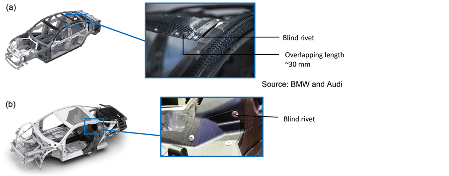
Figure 1. Application of blind riveting in the car body construction to create FRP and metal hybrid components, (a) in the new BMW 7 series; (b) in the Audi R8 e-tron.
requirements of the joint.
Currently used thermosetting FRP-materials, with long production cycle times of a few minutes, are chemically cross-linked after they are brought to their final shape. Therefore, they can’t be reshaped after this process. Then again, finished parts can be made out of pre-consolidated thermoplastic FRP- semi-finished-products (Organic Sheets) in a few seconds, since the matrix only needs to get heated up again to reversibly change its state of aggregation. As a result, load introduction zones can be formed subsequently, so that a severing of the fibers can be avoided [7] .
A new joining concept, derived from the “Cold Metal Transfer Welding” (CMT), gives the decisive solution approach. The process allows the one-sided, fault-tolerant and fiber-fair joining of the different material groups in short cycle times. With this new joining technology, overlapping areas can be reduced drastically, when compared to usual riveting techniques. Furthermore, areas in which loads are introduced don’t have to be reinforced, so that weight advantages can be achieved.
2. Bionical Inspired Load Introductions for Composite Structures
The analysis of design-principles in nature and their adaptation to defects or flaws in the construction helps when optimizing the design of joints. Trees, e.g., try to maintain a constant stress distribution in the fault zone [8] . If a tree gets damaged by cracks, decay or breaks, the developing stress-overload gets reduced by adding additional or stronger material around the defect. In most scenarios a tree uses both of these alternatives. As shown on Figure 2, the tangential relocation of the wood fibers is used, so that the “dangerous” notch effect, caused by defects such as knotholes, can be countered to achieve a homogeneous stress distribution [9] .
Wood fibers have their maximum strength- and stiffness properties along the fiber-direction. That’s why a tree tries to direct his wood fibers to the biggest

Figure 2. Reduction of the notch effect at knotholes by optimizing the orientation of the wood fibers.
stress direction. The orientation of the wood fibers mostly complies with the direction of the main tension, whereby the shearing between the fibers gets reduced and the most can be made out of the material. This construction principle of nature can be used for technical FRP-Applications to increase the strength at notch-sensitive areas of the component (e.g. at holes or cutouts) or at general load inducing areas.
3. Development of a CMT-Welding-Process for High Bearable FRP/Metal Joints
The newly patented joining technology, developed by the chair “Lightweight design with structured materials (LsM)” and “Joining and Welding Technique (LFT)” at the Brandenburg University of Technology Cottbus-Senftenberg [10] , which is used for joining thermoplastic composites and metal sheets, is also suitable for economic large-scale production. Characterized by short production cycles, an optimized flow of forces and high strength joining properties as well as a high usage of lightweight potential, a new process is provided which can be used in several industrial branches. The main benefits are the reduced need of overlapping lengths while only having one-sided accessibility to the joining location. In comparison to the typical joining methods, such as blind riveting, there are no problems when it comes to shifting/moving of tolerance zones, since pre- drilling operations can be skipped. The pin-process is based on the Cold-Metal- Transfer-Welding technology and is characterized by its reversible wire feed. The filler material gets welded onto a metal part and cut off at the desired spot by using an electrical impulse. The so-called pins are created. The CMT-Pin process and its possibilities are described in [2] [11] . The joining with plastic materials is described in [2] [12] . An already existing method to join metal-with plastic parts in a multi-stage process is the “Hybrid penetrative reinforcement process” (HYPER). In this process the pins are welded onto the metal part and then pressed into a plasticized thermoplastic. Optionally, the plastic can be secured by glue application [13] . The disadvantages of this solution are the needs of additional process steps. This includes the application of the plastic material onto the pins with a following glue application and the need of a press, which is necessary to achieve high joint strengths.
Fiber-reinforced thermoplastic composites can be joined in a material-opti- mized way with cycle times suitable for large-scale production, even after consolidation took place [10] . For this, the plastic matrix needs to be plasticized locally in the joining area, so that the reinforcing fibers can be relocated and optimized for the flow of forces during the joining process, according to bionic principles. The relocation of the fibers at the joining area is shown on Figure 3.
Based on the principles of the thermomechanical drilling (radial displacement of the fibers), as well as the low-heated CMT-Welding, a new joining technology is developed which is able to create highly durable FRP/metal-parts.
The joining process breaks down into 3 process-integrated steps, which are described in the following paragraphs and shown on Figure 4:

Figure 3. Joining area with optimized fiber orientation.

Figure 4. Schematic of CMT-Pin welding process.
1) Preheating of the welding wire and/or the FRP-joining-area
In the first step, the thermoplastic FRP gets positioned, so that it overlaps the metal part. The welding wire is transported into the joining-area through the welding torch. With an additional set, the FRP and the end of the welding wire gets heated up until the specific temperature is reached, whereby this temperature complies with the melting temperature of the FRP-matrix (e.g. Figure 4(a)). The created thermal energy gets induced into the thermoplastic FRP part to partially melt the matrix. The fibers inside of the FRP can now be displaced by the welding wire, so that the flow of forces in fiber direction is not interrupted. Damaging the fibers can now be almost entirely prevented.
2) Delivering of the welding wire into the FRP with subsequent welding onto the metal sheet
The welding torch pierces the thermoplastic FRP with the heated end of the welding wire. Since the welding wire is comparatively thin (1 - 1.2 mm) and the FRP is heated up to the melting temperature of the matrix, the fibers won’t be damaged but displaced by the welding wire. Immediately after the welding wire contacts the metal surface, the welding process begins (e.g. Figure 4(b)). The area where the welding wire is welded to the metal surface is called the pin-base.
The welding process of the pin is dependent on the material of the welding wire, the welding wire diameter and the base material. With a defined speed the wire is moved towards the parts to be joined so that it eventually pierces the FRP. Due to a high starting current, an electric arc is lit. Immediately after that, the current value is lowered, so that the welding wire melts off. Moving the wire with a defined speed, combined with a forward and backward movement, the form of the pin-base is created.
3) Separating the wire by melting/forming the locking head
Subsequently, the upper part of the wire is melted by an electrical separation-pulse, so that the melt droplet forms the locking head in the joining area on the FRP-surface (e.g. Figure 4(c)). A pin with a locking head is created which connects the metal- and the plastic components. The locking head takes up the mechanical constraints by creating a form closure in the direction of the welding-wire-axis.
The CMT-Pin-Welding-Process, used to separate the wire, is dependent on the distance of the welding torch, the material of the welding wire and its diameter, the conveying speed of the wire and its direction (pullback) as well as the current-voltage-time-regime. Depending on how the parameters are chosen, it is possible to form a locking head. Besides sharpened/pointed or flattened tip- styles, it’s also possible to form out the preferred ball-geometry [11] . The locking head can be formed directly above, or burned into, the surface of the FRP, so that no elevation remains on the surface.
4. Specification of Specimens
4.1. CMT Welded FRP/Metal Joints
The mechanical characterization of hybrid material combinations took place with static pull-shear-tests, based on the DIN EN ISO 14273. Samples were made out of organic sheets with a polypropylene matrix and 1.4301 stainless steel (Table 1).
For the experimental studies, single-, two- and three-rowed pin-samples with overlapping-lengths LO, ranging from 10 mm to 20 mm, were created with an experimental setup as shown in Figure 5. The distance between the pins in every specimen type is 5 mm. Figure 6 shows a single-rowed pin sample, which is defined as “Type A”, and a detailed representation of one pin to show the realignment of the fibers after the joining process.
Figure 7 shows the two- and three-rowed specimens, “Type B” and “Type C”.

Figure 5. Experimental setup.

Table 1. Material sample data.
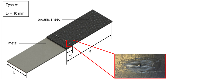
Figure 6. Schematic of single-rowed pin-specimen, “Type A”.

Figure 7. Schematic of pin-specimens, “Type B” and “Type C”.
4.2. Reference Joints
For comparison, specimens with one and two blind rivets with overlapping lengths LO = 35 mm were tested, based on the DIN EN ISO 14273. Each sample type, either with one or two blind rivets, was produced with 3 layers of GFRP.3 samples were tested for each type of specimen. The specimens are described as a schematic in Figure 8 and shown in Figure 9 and Figure 10.
The following diagram shows the average tensile strength of the reference joints.

Figure 8. Schematic of pin-specimens with one and two blind rivets.

Figure 9. Specimens joined with one and two blind rivets.

Figure 10. Static pull-shear test results of 1 and 2 blind rivets.
5. Characterization of CMT Welded FRP/Metal Joints
As described in Chapter 4.1, the specimens, joined with the CMT welding technology, are categorized into 3 types. The specimens were tested with an “Instron ElectroPuls E10000” testing-machine, using a traverse speed of 2 mm/min. Each type of joint was tested with 4 specimens. The results are shown in Figure 11.
To be able to see if the welding wire damaged the fibers by piercing the FRP, even if the composite part is thicker than 2 mm, a non-destructive analysis of a representative joint with a composite part consisting of 11 layers is done by using a micro computer tomograph (Micro-CT) BRUKER SkyScan1172. The metal and CFRP parts have vastly different densities. For the depiction of the fibers in high quality, the metal part had to be removed. To permeate the metal, the energy of the X-ray radiation has to be so high, that the fibers would have been overexposed. For this purpose, the metal pin was separated from the FRP component, so that the FRP component could be scanned with a power of 64 kV. It took the scanner 5 hours to complete the scan at a resolution of 5 μm and radiography with a minimum of 47%. Figure 12 shows the FRP component, after being separated from the metal component.
Recognizable are the 11 layers of the FRP fabric and the joining area of the pin.
The transformation of the x-ray images to 2D images was made with the software NRecon, while the evaluation of these images was done by the software

Figure 11. Static pull-shear test results of the different pin-specimen types.

Figure 12. Computer tomography of the FRP component.
CTAnalyse. The turns in the fiber, as seen on Figure 13, are an exemplary presentation of the layers 1, 6 and 11. All of the reinforcing fibers, contained in the fabric layers, are optimal displaced at the load introduction area, regarding the flow of forces. Regardless of the position of the fabric layer, a breaking of the fiber itself can be avoided to the greatest possible extent.
To compare the new joining technology with the blind-riveting, the strength of the blind riveting samples and the CMT pin samples are compared in Figure 14.
In comparison, the specimen types joined with the CMT-Pin technology show a higher max. Strength than the blind rivet samples.
6. Summary and Outlook
Shear-pull-tests, based on the DIN EN ISO 14273, were performed for the samples, created with the new fiber fair CMT-Pin joining process. The test results of the specimens, joined with the new joining technology, show a much higher strength than the blind-riveting reference joints. The main reason for that is the fiber-fair relocation of the reinforcing fibers inside of the FRP. Since no pre- drilling and -punching process is needed, fibers inside the joining area won’t be

Figure 13. Detail shots of the FRP/metal joining area.

Figure 14. Comparison of the pin- and the blind rivet-samples
damaged, thus leading to lower notch stress. Varying the number of rows increases or decreases the max achieved tensile strength.
Since the Type-A pin specimens almost lead to the tensile strength of 2 blind rivets, one-rowed CMT-Pin joints can be used in technical applications. This leads to constructive benefits when designing a multi-material mixed construction because low overlapping lengths can be chosen, as shown in Figure 15.
When using conventional joining processes such as blind riveting, a minimal distance to the edge of the organic sheet and to the edge of the metal sheet Ra = 3・dshaft is recommended [14] . The diameter of the used blind rivets in the static pull-shear tests is 5 mm, which leads to a recommended Ra of at least 15 mm to each side. This would result into an overlapping length of 30 mm. For safety reasons, another 5 mm were added on top of this value, resulting into Ra = 35 mm, defined as L0 = 35 mm in chapter 4.2. Joining zones with this Ra will have a lot of overlapping material which increases the mass of the part and lowers the lightweight potential of the structure. The overlapping area of the new CMT-Pin welding technology ranges from L0 = 10 mm to L0 = 20 mm, depending on the number of pin rows. This saves a lot of material which is not required for the design of the part and therefore lowers the overall weight of the structure.
Furthermore, the computer tomographic examinations showed that an unwanted breaking of the fiber at the joining areas can be avoided by using the new joining technology. By plasticizing the thermoplastic matrix, the reinforcing fibers can be pushed aside by the welding wire, thus staying functional. Destroyed fibers in the joining area lead to high notch stresses which are up to 10 times as high as the occurring normal stress.
With the new, modified CMT-Welding-Process, highly durable multi-ma- terial hybrid parts, made out of metal and organic sheets can be produced. The great advantage over the mechanical joining process is the possibility to join two parts, while only having one-sided accessibility to the joining location, as well as the fault-tolerant and fiber-optimized application of local load introduction areas. The GMAW-welding-technology, suitable for large-series production, sets the starting point, which is combined with the plasticizing of the thermoplastic

Figure 15. Comparison of the overlapping areas when using blind riveting or the CMT- Pin process.
FRP thus leading to a fiber-fair relocation of the fibers. Additional potential to increase the strength of the joint is given by optimizing the arrangement and calibrating the diameter of the pins. Both aspects are currently the subject of ongoing investigations.
Cite this paper
Seidlitz, H., Fritzsche, S., Ambrosio, M. and Kloshek, A. (2017) Advanced Welding Technology for Highly Stressable Multi-Material Designs with Fiber-Reinforced Plastics and Metals. Open Journal of Composite Materials, 7, 166-177. https://doi.org/10.4236/ojcm.2017.73010
References
- 1. Lambiase, F., Durante, M. and Di Illio, A. (2016) Fast Joining of Aluminum Sheets with Glass Fiber Reinforced Polymer (GFRP) by Mechanical Clinching. Journal of Materials Processing Technology, 236, 241-251.
https://doi.org/10.1016/j.jmatprotec.2016.04.030 - 2. Hackl, H. and Bruckner, J. (2013) Auswirkungen des Multimaterial-Leichtbaus auf die Fügetechnik. Automobil Technische Zeitschrift, 115, 808-813.
https://doi.org/10.1007/s35148-013-0279-9 - 3. Collins, M.W. and Brebbia, C.A. (2006) Design and Nature II: Comparing Design in Nature with Science and Engineering. 6th Edition, WIT Press, Southampton.
- 4. Osiecki, T., Seidlitz, H., Gerstenberger, C., Kroll, L. and Scholz, P. (2014) Customized Metal/Composite Hybrids for Automotive Applications. Tagungsband AutoMetForm/SFU, Freiberg, 29-36.
- 5. Joesbury, A. (2015) New Approaches to Composite Metal Joining. Ph.D. Thesis, Cranfield University, Bedford.
- 6. Seidlitz, H. and Kroll, L. (2014) Hochfeste Mischbauweisenmit Thermoplastischen Faserverbunden und Metallen. Z. Joining Plastics—Fügen von Kunststoffen, 8, 106-111.
- 7. Seidlitz, H., Winter, L. and Kroll, L. (2014) New Joining Technology for Optimized Metal/Composite Assemblies. Journal of Engineering, 2014, Article ID 958501, 11.
- 8. Seidlitz, H. (2013) Entwicklung von Kraftflussgerechten Verbindungstechniken für Mischbauweisen Mitthermoplastischen Faserverbunden und Metallen. Ph.D. Thesis, Technische Universitat Chemnitz, Chemnitz.
- 9. Mattheck, C. (2013) Bauteiloptimierung nach dem Vorbild der Natur—Der Baum als Lehrmeister. VDI-Fachtagung Blasformen, Baden-Baden.
- 10. Seidlitz, H., Michailov, V. and Schleuβ, L. (2015) Verbindungstechnik für Verbundkonstruktionen aus Metall und FVK/Brandenburgische Technische Universitat Cottbus-Senftenberg. DE Patent No. 10 2015 114 511.1 (Anmeldetag: 22.10.).
- 11. Stieglbauer, W. and Kazmaier, J. (2009) Innovative, Multifunctional, Form-Locked Joining Technologyfor Dissimilar Material Combinations; Innovative, Multifunktionale, Formschlüssige Fügetechnologie für die Kombination Verschiedenartiger Werkstoffe. DVS-Berichte, 258, 100-103.
- 12. N.N. (2009) Metall mit Organischem Materialverpinnen. Fronius Press.
http://www.fronius.com/cps/rde/xchg/SID-BABD4D30-DB708F5A/fronius_international/hs.xsl/79_20055_ENG_HTML.htm?inc=82968.htm#.V2ukgLiLRpg - 13. Jahn, J., Weeber, M., Boehner, J. and Steinhilper, R. (2016) Assessment Strategies for Composite-Metal Joining Technologies—A Review. 26th CIRP Design Conference, Stockholm, 15-17 June 2016.
https://doi.org/10.1016/j.procir.2016.05.034 - 14. Schürmann, H. (2007) Konstruieren mit Faser-Kunststoff-Verbunden. Springer-Verlag, Berlin.