Open Journal of Composite Materials
Vol.06 No.04(2016), Article ID:71164,11 pages
10.4236/ojcm.2016.64012
Fiber Line Optimization in Single Ply for 3D Printed Composites
Yusuke Yamanaka1, Akira Todoroki2, Masahito Ueda3, Yoshiyasu Hirano4, Ryosuke Matsuzaki5
1Tokyo Institute of Technology, Tokyo, Japan
2Department of Mechanical Engineering, Tokyo Institute of Technology, Tokyo, Japan
3Department of Mechanical Engineering, Nihon University, Chiyoda-ku, Tokyo, Japan
4Aeronautical Technology Directorate, Japan Aerospace Exploration Agency, Mitaka-shi, Tokyo, Japan
5Department of Mechanical Engineering, Tokyo University of Science, Noda-shi, Japan

Copyright © 2016 by authors and Scientific Research Publishing Inc.
This work is licensed under the Creative Commons Attribution International License (CC BY 4.0).
http://creativecommons.org/licenses/by/4.0/


Received: September 2, 2016; Accepted: October 9, 2016; Published: October 12, 2016
ABSTRACT
In conventional manufacturing processes of composites, Carbon Fibre Reinforced Plastic (CFRP) laminates have been made by stacking unidirectional or woven prepreg sheets. Recently, as a manufacturing process of CFRP, 3D printing of CFRP composites has been developed. The 3D printing process of CFRP composites enables us to fabricate CFRP laminates with arbitrary curvilinear fibre plies. This indicates that the optimization of the in-plane curved carbon fibre placement in a planar ply is strongly required to realize superior 3D printed composites. In the present paper, in-plane curved carbon fibre alignment of a ply with an open hole is optimized in terms of maximization of the fracture strength. For the optimization process, a genetic algorithm is adopted. To describe curved carbon fibre alignments in a planar ply, stream lines of perfect flow is employed. By using the stream lines of the perfect flow, number of optimization parameters is significantly reduced. After the optimization, the fracture strength of CFRP laminate is compared with the results of unidirectional CFRP ply. The curved fibre placement in a planar ply shows superior fracture improvement.
Keywords:
Composites, Carbon Fibre Reinforced Plastic, Optimization, 3D Print, Genetic Algorithm, Curvilinear Fibre

1. Introduction
Carbon Fibre Reinforced Polymer (CFRP) composites are applied in aerospace and automobile industry because of the high specific strength and the high specific modulus of the CFRP composites. The mechanical properties of the CFRP composites significantly depend on the direction of the carbon fibre. This gives us an additional chance to optimize the fibre direction of CFRP composite structures.
Conventional CFRP laminates are manufactured by stacking prepreg plies. The optimizations of the stacking sequence of the CFRP laminates are, therefore, the most important issue for the conventional CFRP laminates. Many researchers have proposed the stacking sequence optimization methods [1] - [8] . In these researches, each ply has straight unidirectional fibre and the stacking sequences of the fibre angles of the target laminate are the optimization results in these papers.
Recently, a brand new manufacturing method of 3D printed CFRP composites has been developed [9] - [13] . The 3D printed CFRP composite method gives us a new chance to extend design freedom of fibre placement by using curved lines in a ply and the fibre direction is not limited to unidirectional in a ply. It enables us to place carbon fibre as shown in Figure 1, by controlling movement of a 3D printer head.
To make distributed different fibre angles in a ply, researches [14] - [16] have used divided FEM mesh of the optimization target domain and they selected fibre angles or stacking sequences for the each divided FEM mesh. In the optimization methods, fibre angles or stacking sequences are given to each divided FEM mesh. This brings discrete fibre angles in each mesh and large discrepancy of fibre angles between the adjacent meshes or nodes. To manufacture the CFRP composites, continuous fibre placement is required for the 3D printed CFRP composites, and the fibre bundles must not have an intersection. This indicates that a new optimization method using continuous fibre placement without an intersection is indispensable.
In the present study, therefore, continuous curved carbon fibre placement in a ply is optimized with a stream line method used for analyses of perfect fluid. The stream lines of the perfect fluid are intrinsically continuous and do not have an intersection with each other. The new optimizing method using the fibre stream line is, therefore, adopted as a suitable method for the manufacturing of 3D printed CFRP composites. The newly developed optimization method using the stream lines reduces number of design parameters significantly, and the method realizes continuous results of fibre direction without an intersection of fibre bundles. The objective function of the present

Figure 1. Schematic representation of the 3D printed CFRP composite ply with curvilinear fibre placement.
paper is to improve the fracture strength of a ply with an open hole. The present study deals with a fibre placement in a ply, and stacking optimizations of plies are our future projects.
2. Optimization Problem
The optimization target domain is an open-hole-single-ply plate as shown in Figure 2. The longitudinal direction of the specimen is aligned to the x-axis and is defined as the 0˚ fibre angle. The single ply plate is subjected to tensile load in the longitudinal direction. As a tensile load, tensile stress of 400 MPa is applied to the both edges. Mechanical properties of CFRP and matrix used in present study are shown in Table 1 and Table 2 [17] - [19] . The optimization target specimen is divided into FEM mesh as shown in Figure 3. The total number of elements is 5440, and the total number of nodes is 16,720. In the present study, fracture of each element is judged by using Tsai-Wu fracture criteria as follows.

Figure 2. Configuration of the optimization target.

Table 1. Mechanical properties of CFRP [17] - [19] .

Figure 3. FEM model of the optimization target under the tensile loading in x direction.
Table 2. Mechanical properties of matrix [17] - [19] .
 (1)
(1)
where S1 is stress in carbon fibre direction, S2 is stress in transverse direction to the carbon fibre, t12 is shearing stress, FLt is tensile strength in carbon fibre direction, FLc is compressive strength in carbon fibre direction, FTt tensile strength in transverse to carbon fibre direction, FTc is compressive strength in transverse to carbon fibre direction, FLT is shearing strength.
Fracture of the each element is judged when the Tsai-Wu fracture index λ exceeds 1. The objective function of the present study is to minimize the maximum value of the Tsai-Wu fracture index λ.
Two types of fibre placement optimizations are conducted in the present study: non-symmetric and symmetric as shown in Figure 4 and Figure 5 respectively To draw the stream lines, sources, sinks and vortexes that are usually used to express perfect fluid flow, are employed in both types of the optimizations. The non-symmetric optimization shown in Figure 4 consist of two source points (blue dots), two sink points (red dots), ten fibre vortexes (green dots), and a column (yellow dot). The symmetrical optimization, as shown in Figure 5, is consist of two source points, two sink points, four fibre vortexes, and a column. The number of these elements is decided by a trial and error method.
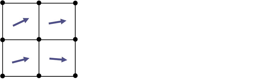
To calculate the Tsai-Wu fracture index of at the various elements, FEM analysis is indispensable. The FEM analysis requires the fibre angle for each element to obtain the stiffness. Fibre angle of each element is defined from the continuous curves of the fibre stream lines in the present study. Carbon fibre direction of the each FEM element is decided by using the direction of the fibre stream line at the center of each element, as shown in Figure 6.

Figure 4. Configuration of the non-symmetric optimization with 2 source points, 2 sink points, 10 fibre vortexes, and a column.

Figure 5. Configuration of the symmetric optimization with 2 source points, 2 sink points, 4 fibre vortexes, and a column.
 (a) (b)
Figure 6. Decision of the fibre direction to FEM elements. (a) Direction of streamline; (b) Discrete FEM model.
Figure 7 shows the special region where the fibre stream lines have extremely large curvature around a vortex. A fibre vortex makes eddying flow around the center of the vortex. This makes extremely curved carbon fibre bundle. Considering about practical carbon fibre placement in 3D printed composites [8] - [13] , it is quite difficult to realize
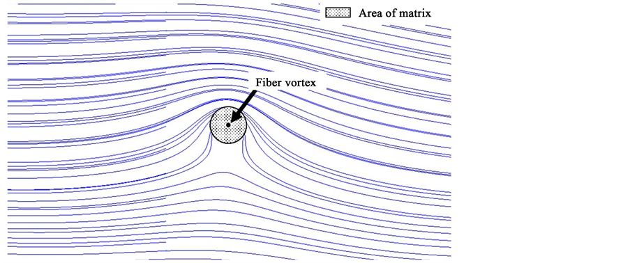
Figure 7. Enlarged view around a fibre vortex.
these fibre placement of the extremely large curvature. To remove these large curvature points, the property of the matrix is given to the elements where the element center locates within the distance of 10mm from the center of the fibre vortex. This means the fibre bundle is not placed at the element. The gray circle shown in Figure 7 represents the area of 10mm distance from a fibre vortex.
3. Optimization Method
The objective function of the present study is to maximize fracture stress, which is equal to the minimization of the maximum value of the Tsai-Wu fracture index. For the optimization process, a well-known genetic algorithm is employed. The design variables are shown in Table 3 and Table 4. The maximum limit values and the minimum limit values of the design parameters are also shown in both of the table.
In the present study, a MATLAB Genetic Algorithm (GA) optimization toolbox is used for the optimizations. As a first procedure of the GA, the initial individuals are made by Latin Hypercube Sampling. For example, in the case of the non-symmetric optimization, each individual has 34 variables that satisfy the maximum limit and the minimum limit value requirements shown in Table 3. In the case of the symmetric optimization, each individual has 6 variables that satisfy the maximum limit and the minimum limit value requirements shown in Table 4. FEM analysis is performed and the fitness of the individual is evaluated by the maximum value of the Tsai-Wu fracture index value in all elements. In the present study, a commercially available FEM analysis software ANSYS (Ver 15.0) is used. ANSYS is set to be called by the MATLAB GA tool box program to evaluate the fitness function of each individual. After the every evaluation of every individual, parents for the crossover are selected by a normal roulette selection. The child is made by a uniform cross over, mutation, and an elite preservation is employed. This procedure is cycled up to the 250 generations, however if the relative change of the average value over 250 is less than or equal to 1.0 × 10⁻⁶, the GA process is terminated. The parameters of the GA in the present study are shown in Table 5.
Table 3. Optimization parameters of non-symmetric flow field.
Table 4. Optimization parameters of symmetric flow field.
Table 5. GA parameters used for the present study.
4. Results and Discussion
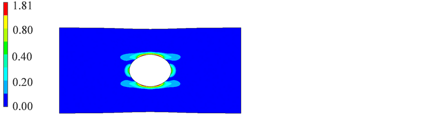
Before the optimization of the fibre placement, an optimization of the fibre angle of unidirectional ply of the specimen shown in Figure 2 is performed. The obtained result shows that the 0˚ unidirectional ply shown in Figure 8 has the minimum Tsai-Wu fracture index compared to the other fibre angles. The highest fracture index of the 0˚

Figure 8. Optimal results of fibre direction of uniformly unidirectional composites.
unidirectional ply is λ = 1.81. This means that the fracture occurs approximately 55% of the reference applied load. The results of the GA are compared with the result of 0˚ unidirectional ply in the present study.
As the GA is one of the stochastic optimization methods, five runs of optimizations are performed for both types by changing random seed, and the best value is searched in the present study. The best Tsai-Wu fracture index of the non-symmetric type is λ = 0.64, and that of the symmetric type is λ = 0.61. The fracture index λ = 0.64 means that the fracture occurs at 128% of the applied reference load. Compared to the result of the 0° unidirectional ply, the fracture index obtained by the GA with flow stream lines is significantly improved in both types.
Obtained optimized fibre placement of the non-symmetric type is shown in Figure 9 and that of the symmetric type is shown in Figure 10. As shown in Figure 9, fibre stream lines are largely affected by fibre vortexes locate inside of the specimen area. Some of the fibre vortexes locate out of laminate as shown in the bottom of Figure 9. These vortexes locate out of the specimen area have smaller effect on the fibre stream lines. Tsai-Wu index value contour of each optimized result is shown in Figure 11. For the unidirectional specimen, the higher Tsai-Wu fracture index values are observed around the open hole as shown in Figure 11(a). For the non-symmetric and symmetric specimens, slightly high Tsai-Wu fracture index value is observed in various areas: the high area is not limited to the adjacent area around the open hole. This comes from the fibre vortexes locate inside of the specimen. The fibre vortexes cause high stress areas that locate far from the open hole, and these scattered high-stress-concentrated areas brings smaller Tsai-Wu fracture index values in the entire specimen.
Although there is slight difference of the Tsai-Wu index values between the non- symmetric specimen and symmetric specimen, the difference is very small. As the Tsai-Wu index value is calculated using the approximation of the fiber direction of each FEM element as described before, the difference seems negligible. This result shows that the symmetric and non-symmetric placement of fibre vortexes have small effect on the increase of Tsai-Wu index value. The Tsai-Wu fracture index value surely increased using the fibre vortexes. This means that the curved fibre placement has possibility to increase the fracture strength of CFRP composites. Fracture of laminated CFRP is our future work.

Figure 9. Optimal results of fibre direction of no-symmetric specimen.

Figure 10. Optimal results of fibre direction of symmetric specimen.
 (a)
(a)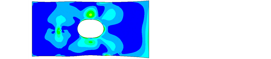 (b)
(b) (c)
(c)
Figure 11. Tsai-Wu index of the optimized results.
5. Conclusion
In the present paper, a new optimization method to provide continuous curved fibre placement without inter-section of fibre bundles in a ply is proposed for the 3D printed continuous fibre composites. The new method adopts stream lines of perfect fluid using sources, sinks and vortexes. The method automatically provides curved fibre lines without an intersection, which is indispensable for actual processing of 3D printed composites. The optimization method is applied to an open-hole single ply under tensile stress and the fracture stress of the ply is maximized by changing fibre placement. As a result, the fracture stress increases up to 173% compared with the unidirectional ply. This indicates that there is possibility to increase composite performance by changing fibre placement in a ply.
Acknowledgements
The present research was performed with the found of “Development of Numerical Simulation Methods for Cost-Effective Aircraft Design Development of Structure Design Simulation Technologies for Aircrafts, Development of Technologies for Next- Generation Structure Component: Creation and Processing” by New Energy and Industrial Technology, Development Organization of the Japanese government in 2015 and 2016. I would like to express sincerely thanks to them.
Cite this paper
Yamanaka, Y., Todoroki, A., Ueda, M., Hirano, Y. and Matsuzaki, R. (2016) Fiber Line Optimization in Single Ply for 3D Printed Composites. Open Journal of Composite Materials, 6, 121-131. http://dx.doi.org/10.4236/ojcm.2016.64012
References
- 1. Miki, M. (1985) Design of Laminated Fibrous Composite Plate with Required Flexural Stiffness. ASTM STP, 864, 387-400.
- 2. Fukunaga, H. and Chou, T.W. (1998) Simplified Design Techniques for Laminated Cylindrical Pressure Vessels under Stiffness and Strength Constraints. Journal of Composite Materials, 22, 1156-1169.
http://dx.doi.org/10.1177/002199838802201206 - 3. Le Richie, R. and Haftka, R.T. (1993) Optimization of Laminate Stacking Sequence for Buckling Load Maximization by Genetic Algorithm. AIAA Journal, 31, 951-956. http://dx.doi.org/10.2514/3.11710
- 4. Todoroki, A., Sasada, N. and Miki, M. (1996) Object-Oriented Approach to Optimize Composite Laminated Plate Stiffness with Discrete Ply Angles. Journal of Composite Materials, 30, 1020-1041.
http://dx.doi.org/10.1177/002199839603000904 - 5. Todoroki, A. and Haftka, R.T. (1998) Stacking Sequence Optimization by a Genetic Algorithm with a New Recessive Gene like Repair Strategy. Composites Part B: Engineering, 29, 277-285.
http://dx.doi.org/10.1016/S1359-8368(97)00030-9 - 6. Liu, B., Hatka, R.T., Akgun, M.A. and Todoroki, A. (2000) Permutation Genetic Algorithm for Stacking Sequence Design of Composite Laminates. Computer Methods in Applied Mechanics and Engineering, 186, 357-372.
http://dx.doi.org/10.1016/S0045-7825(99)90391-2 - 7. Todoroki, A. and Terada, Y. (2004) Improved Fractal Branch and Bound Method for Stacking Sequence Optimizations of Laminated Composite Stiffener. AIAA Journal, 42, 141-148.
http://dx.doi.org/10.2514/1.9038 - 8. Todoroki, A. and Sekishiro, M. (2008) Modified Efficient Global Optimization for a Hat-Stiffened Composite Panel with Buckling Constraint. AIAA Journal, 46, 2257-2264.
http://dx.doi.org/10.2514/1.34548 - 9. Namiki, M., Ueda, M., Todoroki, A., Hirano, Y. and Matsuzaki, R. (2014) 3D Printing of Continuous Fiber Reinforced Plastics. Proceedings of SAMPE, Seattle, 2-5 June 2014, #4328.
- 10. Mori, K., Maeno, T. and Nakagawa, Y. (2014) Dieless Forming of Carbon Fibre Reinforced Plastic Parts Using 3D Printer. Procedia Engineering, 81, 1595-1600.
http://dx.doi.org/10.1016/j.proeng.2014.10.196 - 11. van der Klift, F., Koga, Y., Todoroki, A., Ueda, M., Hirano, Y. and Matsuzaki, R. (2016) 3D Printing of Continuous Carbon Fibre Reinforced Thermo-Plastic (CFRTP) Tensile Test Specimens. Open Journal of Composite Materials, 6, 18-27.
http://dx.doi.org/10.4236/ojcm.2016.61003 - 12. Matsuzaki, R., Ueda, M., Namiki, M., Jeong, T.K., Asahara, H., Horiguchi, K., Nakamura, T., Todoroki, A. and Hirano, Y. (2016) Three-Dimensional Printing of Continuous-Fiber Composites by In-Nozzle Impregnation. Scientific Reports, 6, Article Number: 23058.
http://dx.doi.org/10.1038/srep23058 - 13. Tian, X.Y., Liu, T.F., Yang, C.C., Wang, Q.R. and Li, D.C. (2016) Interface and Performance of 3D Printed Continuous Carbon Fiber Reinforced PLA Composites. Composites Part A: Applied Science and Manufacturing, 88, 198-205. http://dx.doi.org/10.1016/j.compositesa.2016.05.032
- 14. Zafer, G. and Reynaldo, O. (1993) In-Plane Response of Laminates with Spatially Varying Fiber Orientations Variable Stiffness Concept. AIAA Journal, 31, 751-758.
http://dx.doi.org/10.2514/3.11613 - 15. Hossein, G., Kazem, F., Damiano, P. and Larry, L. (2010) Optimum Stacking Sequence Design of Composite Materials Part II: Variable Stiffness Design. Composite Structures, 93, 1-13.
http://dx.doi.org/10.1016/j.compstruct.2010.06.001 - 16. Shahriar, S., Mostafa, M.A. and Zafer, G. (2006) Design of Variable-Stiffness Laminates Using Lamination Parameters. Composites Part B: Engineering, 37, 301-309.
http://dx.doi.org/10.1016/j.compositesb.2005.12.001 - 17. Shigemori, K., Hosoi, A., Fujita, Y. and Kawada, H. (2014) Fatigue Strength Properties of Interlaminar Toughened CFRP Laminates under Cyclic Loading in the Out-of-Plane Direction. Transactions of the JSME, 80, SMM0087. (In Japanese)
- 18. Matsui, J., Nomura, S. and Ishii, Y. (1986) On the Relation between Mechanical Properties of Carbon Fibres and Those of Composite Materials-Tensile Properties. Journal of the Japan Society for Composite Materials, 12, 109-115. (In Japanese)
http://dx.doi.org/10.6089/jscm.12.109 - 19. Matsui, J., Nomura, S. and Ishii, Y. (1986) On the Relation between Mechanical Properties of Carbon Fibres and Those of Composite Materials-Compressive and Shear Properties. Journal of the Japan Society for Composite Materials, 12, 251-258. (In Japanese)
http://dx.doi.org/10.6089/jscm.12.251