Open Journal of Composite Materials
Vol.4 No.3(2014), Article
ID:47835,16
pages
DOI:10.4236/ojcm.2014.43018
Dimensioning of Punctiform Metal-Composite Joints: A Section-Force Related Failure Criterion
Holger Seidlitz*, Lars Ulke-Winter, Colin Gerstenberger, Lothar Kroll
Institute of Lightweight Structures, Chemnitz University of Technology, Chemnitz, Germany
Email: *holger.seidlitz@mb.tu-chemnitz.de
Copyright © 2014 by authors and Scientific Research Publishing Inc.
This work is licensed under the Creative Commons Attribution International License (CC BY).
http://creativecommons.org/licenses/by/4.0/


Received 20 March 2014; revised 28 April 2014; accepted 20 May 2014
ABSTRACT
Reliable line production processes and simulation tools play a central role for the structural integration of thermoplastic composites in advanced lightweight constructions. Provided that material-adapted joining technologies are available, they can be applied in heavy-duty multi-material designs (MMD). A load-adapted approach was implemented into the new fully automatic and faulttolerant thermo mechanical flow drill joining (FDJ) concept. With this method it is possible to manufacture reproducible high strength FRP/metal-joints within short cycle times and without use of extra joining elements for the first time. The analysis of FDJ joints requires a simplified model of the joint to enable efficient numerical simulations. The present work introduces a strategy in modeling a finite-element based analogous-approach for FDJ-joints with glass fiber reinforced polypropylene and high-strength steel. Combined with a newly developed section-force related failure criterion, it is possible to predict the fundamental failure behavior in multi-axial stress states. The functionality of the holistic approach is illustrated by a demonstrator that represents a part of a car body-in-white structure. The comparison of simulated and experimentally determined failure loads proves the applicability for several combined load cases.
Keywords:Composites, Multi-Material-Design, Hybrid, Joining, Failure Criterion, FDJ Joint

1. Introduction
Increasing environmental and economic demands in mechanical engineering as well as vehicle and aircraft construction require specific material combinations and dedicated manufacturing processes [1] . Due to the achievable synergy effects, especially in automotive lightweight design, multi-material assemblies are increasingly applied [2] . For this purpose the use of thermoplastic FRP—in conjunction with classical isotropic materials like steel or aluminum—offers several advantages in specific characteristics and manufacturing properties [3] . To reach the aims of high strength and fault-tolerance, special attention must be paid in joining the different material groups. The joining technology must be precisely matched to the material-pairing, in order to take advantage of the high strength potential of the FRP [4] . Conventional joining methods such as screwing and riveting meet these criteria only insufficiently [5] . Thus the development of novel joining processes is crucial [6] [7] . To establish new technologies in industrial practice, aside from the process control and optimization, integration into computer aided engineering (CAE) environments is an important prerequisite. For instance, structural components can be optimized with respect to the component stiffness or crash resistance by simulation models [8] [9] .
Modern vehicle designs usually involve several thousand joints whose integration will need to succeed quickly and in a simple fashion due to the necessary number of models. To obtain simulation results with sufficient accuracy, the consideration of these joints is of paramount importance. Taking into account a detailed description of the joint zone in the overall model results in extremely time consuming simulations [10] [11] .
The present work offers a guideline for the analysis and the description of joint failure at FRP/metallightweight assemblies, using the example of the new developed FDJ concept. Due to the development of a finite element based analogous model, load-specific cross-sectional forces are evaluable at the FDJ-joint. Conventional stress-based simulation methods require the consideration of the fiber distribution, fiber alignment and fiber damage in modeling the FRP joint [12] . By contrast, the new approach only considers the acting cross-section forces at the joint. However, this will allow realistic simulations of the joint with sufficient accuracy. Furthermore, the simple structure of the analogous model allows the simulation of joining spots in complex models without increasing the computational complexity in the finite element analyzes (FEA). The output of a FE simulation can be plugged into the failure criterion to accurately predict joint failure, rendering expensive destructive testing is superfluous.
2. Bionic Optimization of FRP
Analyzing structural regulation principles in nature provides a solution for the shape optimization of the joining point. For instance, the preservation of a uniform stress distribution is observed at knot-holes of trees [13] [14] . Due to the re-aligned wood fibers, critical notch effects can be reduced significantly at the defect zone [15] .
To increase the strength of technical FRP components this bionic solution can be used as a design model for the load capable arrangement of reinforcing fibers at load application areas—e.g. on drilled holes or cut outs. Based on this principle, optimization algorithms were developed allowing the alignment of fibers into the directions of principal stresses [16] [17] . Since the fiber component has the highest young’s modulus and strength in the longitudinal direction, the FRP component is gradually optimized by the specific arrangement of reinforcing fibers. The schematic procedure is described in Figure 1 with the aid of the finite element analysis as an example of a tensile-loaded unidirectional reinforced open-hole shell model.
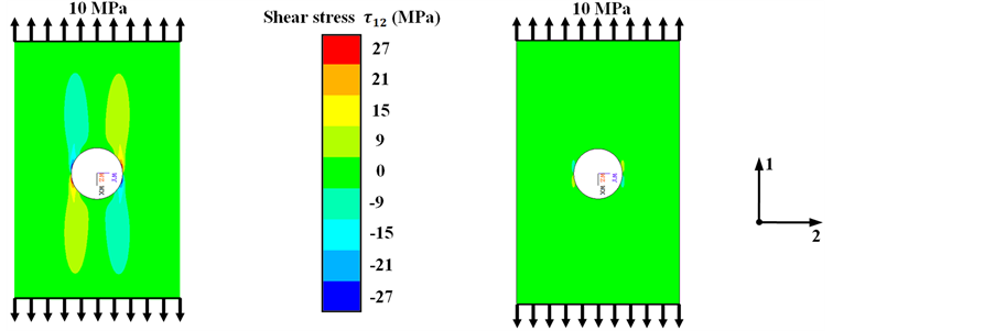
The comparison of determined shear stress distributions at the edges of the open holes shows that the classical discontinuous fiber orientation causes a relatively high stress concentration at the notch (Figure 2(a)). In contrast, the optimized unidirectional FRP plate with tangential fiber alignment exhibits significant lower shear stresses at the circular cutout (Figure 2(b)).
3. Flow Drill Joining Concept
The principle of the local fiber realignment—similar to designs in nature—has inspired the development of a new joining approach at the Institute of Lightweight Structures at Chemnitz University of Technology (CUT) [18] -[20] . The resulting joining technology is suitable for manufacturing multi-material designs with thermoplastic composites and metals.
Characterized by short cycle times and high strength properties, it is applicable for mass production in various industrial sectors. Compared to typical joining methods, the principal advantage is the avoiding of additional auxiliary joining elements.
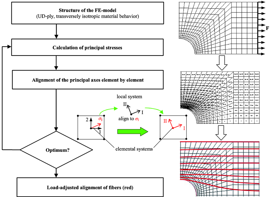
Figure 1. Determination of the optimum fiber orientation for a quarter model of a tensile loaded UD-reinforced open-hole shell model.
 (a) (b)
Figure 2. Shear stress distribution  at FRP plates with open holes: (a) unidirectional and (b) load adjusted alignment of reinforcing fibers.
3.1. Manufacturing of FDJ Joints
Multi-material FDJ joints exploit the flow properties of the metaland polymer components purposefully. With the help of a rotating mandrel the metallic bushing gets thermomechanically shaped from the metallic sheet through the FRP component. The process temperature is close to the recrystallization temperature (for steel about 500˚C - 700˚C). In this range the material is hot formable and therewith flowable. Because of the short processing time the local hot-spot energy is sufficient to plasticize the underlying matrix of the FRP component, without thermal degradation. The temperature management is carried out indirectly through the path and speed controlled plunging of the mandrel. After the mandrel is driven back, the closing head becomes manufactured by re-forming the bushing with a special forming tool (Figure 3).
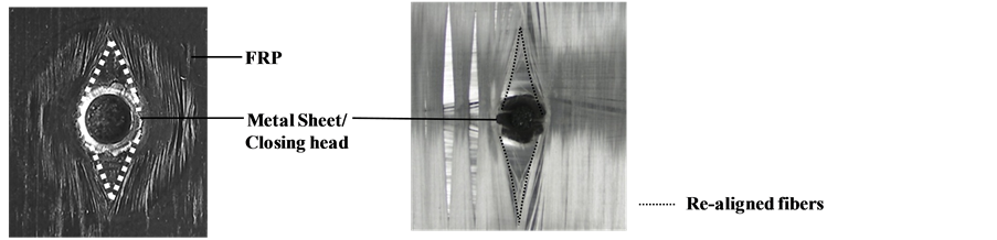
The rotation of the mandrel causes friction on the metal component. The resulting thermal energy is locally induced into the FRP. As a consequence the thermoplastic polymer becomes plasticized. This allows the movement/alignment of the embedded fibers, when the bushing is formed through the FRP component, so that fiber fracture does not occur and the force flux is still maintained (Figure 4).
3.2. Joining Tool
The technological implementation of the described FDJ process was carried out by developing a special joining tong (Figure 5). The joining tool is also applicable at robots and guarantees the manufacturing of complex multi material bodies. For joining of thick walled FRP components, the plasticization of the matrix can be supported by an infrared heating system to reduce the processing time.
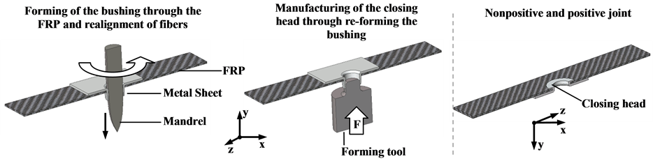
Figure 3. Principle of manufacturing a load adjusted metal/FRP joint.
 (a) (b)
Figure 4. Close up view of realigned fibers at FDJ joints with (a) Steel HX420LAD and orthotropic reinforced polypropylene (PP) as well as (b) with incinerated matrix.

Figure 5. FDJ joining complex with robot, joining tong and demonstrator part.
4. Development of a Cross-Sectional Force Related Failure Criterion
4.1. Approach
To apply new joining technologies in automotive mass production, different requirements must be fulfilled. Short cycle times, reproducible joining qualities and robust finite element (FE) simulation methods for joints are of central importance. In general, the necessity of strength tests at real demonstrator components can be reduced by using suitable simulation models.
The analysis of complex assemblies, like multi-material car body structures, usually requires simplified modeling approaches for the joints to make the numerical simulation as efficient as possible [21] [22] . Due to the high computational costs, an elaborate volumetric modeling of joints is not recommended. In this work a novel analogous model for FDJ joints, which describes relevant structural properties and acting mechanisms, is developed. With the model it is possible to predict the fundamental failure behavior of FDJ joints in multiaxial stress states. Therefore various stress tests must be carried out to verify the approach.
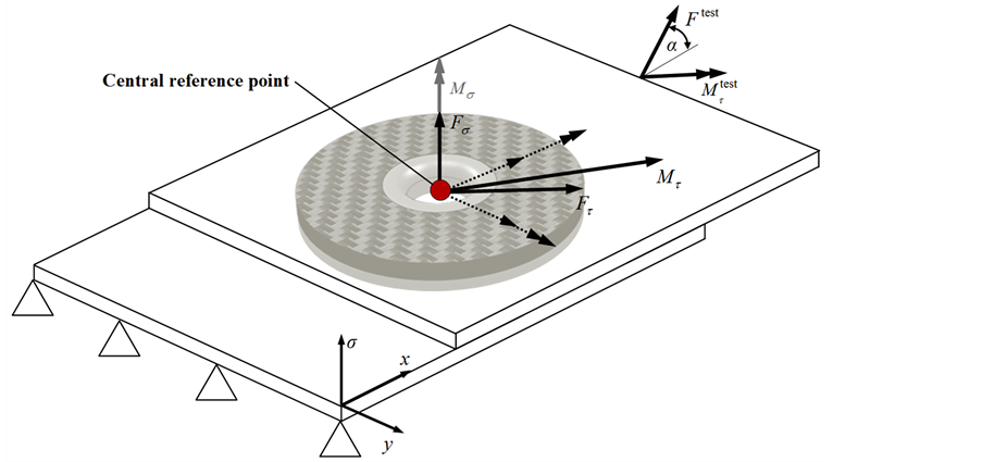
For a uniform analysis of the stress tests, all section forces/moments are related to a central reference point (FDJ joint) between the middle planes of the metal and FRP component (compare Figure 7(a)). The failure critical combination then represents a failure point of a suitable fracture surface. The basic tests include lap-shear, cross-tension, peel tests and furthermore load tests at superimposed stress states (combined lap-shear/cross-tension and torsion/lap-shear tests). The results of the studies provide the basis for the creating a cross-sectional force related fracture criterion (CSFR fracture criterion), whose iso-surface describes the bearable load condition at the joint. A failure-hypothesis with free parameters is formulated and fitted to the experimental data by using regression analysis. Subsequently, the CSFR fracture criterion is verified at representative generic technology demonstrators under multiaxial loading. The whole schematic procedure is illustrated in Figure 6.
4.2. Material Selection
To investigate a CSFR fracture criterion, hybrid joints with hot dipped galvanized high strength steel HX 420 LAD and orthotropic reinforced polypropylene (PP) were prepared. Table 1 and Table 2 summarize the applied joining materials and associated processing parameters (see also attached input deck).
4.3. Basic Load Tests
The FDJ joint transmits comparatively high normal ( ) and shear forces (
 ). In addition a moment is inducible at the joint, which will be referred furthermore to as resultant bending moment
 , Equation (1). In contrast, torsional moments
  (Figure 7(a)) are inducible only to a very small extent. For this reason they will not be considered in the following. The transferable major loads (
 ,
,  ,
, ) define a three-dimensional “experimental space”. Herein the
  -, Equation (2), and the
  -axis comply the failure loads, which will be examined in lap-shear and cross-tension tests. The resulting bending moment is represented by the
  -axis (Figure 7(b)).
 (1)
(1)
 (2)
(2)
The orthogonal planes of the experimental space can be mapped by different quasi static basic tests and their combinations:
•  —plane by combined cross-tension/lap-shear test•
  —plane by combined torsion/ lap-shear test and
•  —plane by peel test.
The results of the test data are the basis for generating the joint model and the CSFR fracture criterion. The design of the test specimens was based on existing standards for testing spot welded joints (DIN EN ISO 14272 and DIN EN ISO 14273). Due to its importance in automotive industry—where it is a widely used method—it has a broad normative background and has been accordingly well documented for technical testing. The listed specimens and geometries of the standards are applicable to any punctiform joints.
As expected for punctiform joints, the FDJ joint shows their highest load capacity under pure shear load (Figure 8). In comparison the maximum cross-tension strength is 50% lower. The studies show a rapid decrease
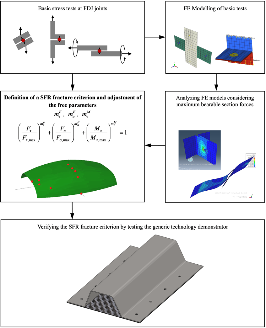
Figure 6. Procedure to realize a cross-sectional force related fracture criterion for FDJ joints.
of tolerable loads in superimposed cross-tension and lap-shear tests. As expected they are reduced to the level of pure cross-tension load when increasing the load angle α with the test device. The peel test examines the behavior of the FDJ joint in superimposed stress states with bending moments and normal forces. The experimental results confirm that peel stresses should be avoided (Figure 9). The superimposed torsion/lap-shear test stresses the joint with a defined lap-shear load. At the same time the joint becomes stressed by a torsional moment. This results, in particular, from the mutual support of the joining partners (contact) complex stresses in the joining point. During the tests six different stress states were investigated at the joints by several biasing forces below the maximum tolerable shear load. In the next step the additionally tolerable torsional moments were determined (Figure 10).

Table 1. Specification of materials.
Table 2. Processing parameters.
 (a)
(a)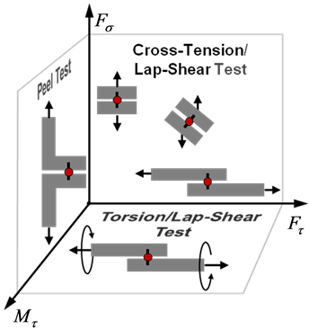 (b)
(b)
Figure 7. Investigation of the CSFR fracture criterion; (a) major load cases at the FDJ joint an (b) plains of the experimental space with schematic illustration of basic tests for characterization.
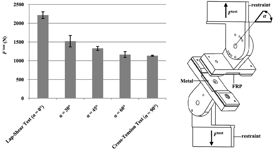
Figure 8. Determination of the  -plane by superimposed cross-tension/lap-shear tests with the test device (Number of tested specimens: 5).
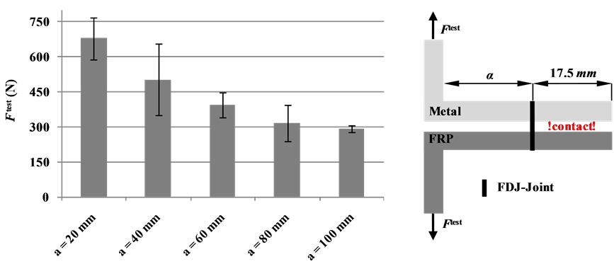
Figure 9. Results of peel test; influence of the lever arm length a to the bearing capability of FDJ joints with schematic illustration of the specimen (width = 50 mm, Number of tested specimens: 5).
4.4. Modeling of the FDJ Joint
Simplified FE-analogous models are used to minimize the computational and modeling effort. Ideally, a joint is described by a single element that can be integrated with little extra effort into the existing FE-mesh. In this article the joint is represented by an ABAQUS JOINTC-element. The auxiliary element characterizes a virtual spring whose six degrees of freedom can be assigned with specific stiffness to represent the joint properties of the material combination.
Since individual FDJ-joints transfer torsional moments around the σ-axis only slightly, there is no stiffness assigned to the spring in this direction. The remaining five degrees of freedom can be determined from the force-displacement curves of the previously conducted basic experiments. The connection between the auxiliary element and the mesh structure of the metallic and FRP-sheets is implemented by multiple point constraints (MPC), whereby the behavior of the joint and its influence on the local structure is mapped (Figure 11).
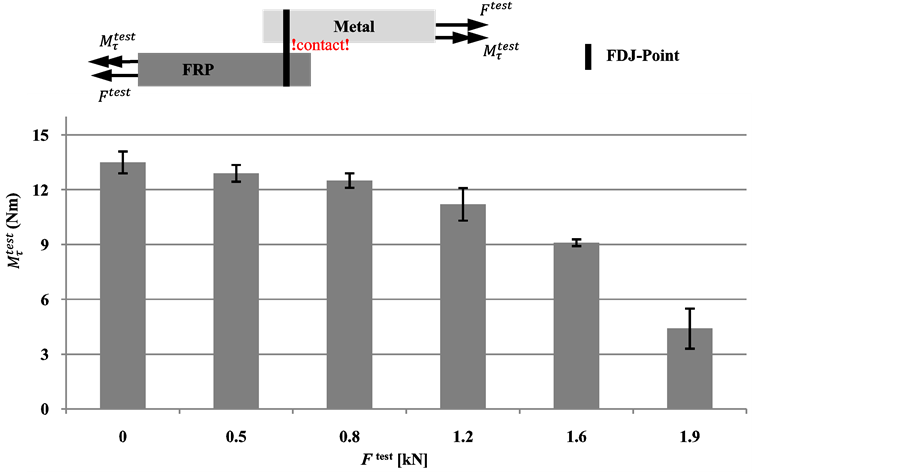
Figure 10. Results of superimposed torsion/lap-shear tests and schematic illustration of the specimen (width = 50 mm, Number of tested specimens: 5).
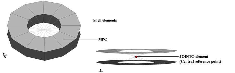
Figure 11. Detail view of the FDJ joint analogous model.
4.5. Failure Criterion
The basis for computing the failure criterion is represented by a generalized equation of an ellipsoid. Provided that shear and torsion failure is sign-independent, the global failure of the FDJ joints can be represented as a symmetric iso-surface. The typical form of an equation for failure criteria’s is obtained in Equation (3), which has been complemented by three exponents. With its aid the approximation of the envelope curve to the determined maximum loads is possible. After transferring the extended equation in the three-dimensional load space ( ,
,  ,
, ) the failure criterion is:
 (3)
(3)
In the next step the three exponents ,
,  and
and  are determined to calibrate the equation. This is achieved by least square regression and basic tests. The resulting failure equation for the investigated FDJ joint and material combination is:
 (4)
(4)
On the  -axis the equation is only valid for positive values, since negative values for FDJ joints represent uncritical cross-pressure loads. Figure 12 shows a three-dimensional plot of the adapted failure criterion. The color-coded dots represent the maximum bearing loads, which were determined in basic tests.
5. Verification
The previously investigated sample configurations consider only an isolated FDJ connection point. However, the verification of the CSFR failure criterion needs to be conducted in multi-axial stress tests on complex representative demonstrators with multiple joints.
5.1. Generic Technology Demonstrator
In car building shear-stressed components, such as spare wheel wells, front bulkheads and components of the vehicle floor are priority made from large-scale sheets. Omega profiles are often used to reinforce thin metal sheets and thus form a complex support structure in stressed-skin construction. Inter alia this includes the so-called undertray, whose structural design is usually divided into the front end of the vehicle with front bulkhead, middle undertray with tunnel and middle crossbeam as well as the rear end with longitudinal crossbeam and rear crossbeam. Here, due to the required high strength and stiffness properties at low density, FRP’s have a high potential when substituting metal-based shear panel constructions. Because of that, the design of the generic technology demonstrator is exemplarily based on the interface between crossbeam and floor panel of an undertray structure (Figure 13).
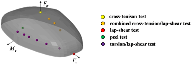
Figure 12. FDJ failure criterion with color-coded maximum loads.
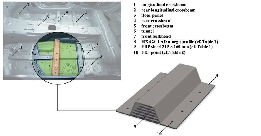
Figure 13. Undertray of a body in white with labeled floor panel (green) as well as crossbeam (brown) and derived generic demonstrator part in multi-material-design.
The production of the demonstrators is divided into the following steps:
• deep-drawing of HX 420 LAD omega profiles• welding of the bearing flange for quasi-static combined tension–torsion loading test• cutting of FRP sheets• joining of FRP and metal components by FDJ joining tong (Figure 6).
To induce the superimposed tensile and torsional loads, a clamping unit is used, which fixes the FRP by four screws (green/brown) (Figure 14). For a nonrotating bearing, a bearing flange is welded at the omega profile of the demonstrator, which is clamped in the testing machine as the solid bearing.
5.2. Numerical Analysis
The numerical simulation of the generic technology demonstrator (Figure 15) was carried out with a nonlinear (because of friction and large deformations) quasi-static FE model with a maximum time step of 10% (cf. attached input deck). All models were built up and solved with the FE software ABAQUS 6.10.3 of Dassault Systèmes. The coulomb friction constant μ was determined experimentally.
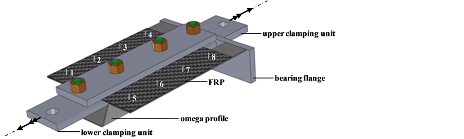
Figure 14. Generic demonstrator with FDJ points 1 - 8, bearing flange and upper and lower clamp for inducing superimposes tensile and torsional load.
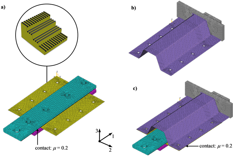
Figure 15. FE modeling of the generic technology demonstrator; (a) upper (cyan) and lower clamping unit (pink) and FRP shet (yellow) with orientation of fibers, (b) bearing flange (grey) with omega profile (violet) and (c) meshed model.
To model the bearing flange (grey), upper (pink) and lower clamping unit (cyan), hexahedral volume elements with quadratic shape function were used. The modeling of the omega profile (violet) and FRP sheet (yellow) was realized by shell elements with an element edge length of approx. 3.0 mm.
To introduce the load at the demonstrator part in a uniform way, the joints at the metallic omega profile and the FRP sheet were modeled with Multi Point Constraints (MPC). At the 8 FDJ-joining points both components are concatenated by 0D spring elements with direction-dependent stiffness behavior and MPC (Figure 16(a)).
At the nodes of the JOINTC elements, section forces and moments are determined at the FDJ-joint in the post-processing step. The modeling of the screws fixing is also realized by MPC, whereas they are connected by beam elements to describe the influence of the screws in the model (Figure 16(b)). The bearing flange is fixed (constrain degree of freedom 1 - 6) when inducing the superimposed tensile/torsion load (constrain degree of freedom 1, 2, 4, 5) by the upper fixing unit (Figure 16(c)).
5.3. Test
At first three load steps with a biasing force of 2.0 kN, 6.0 kN and 10.0 kN were defined and verified according to the use of failure Equation (4). Then the tolerable torsional moment respective to the corresponding preload
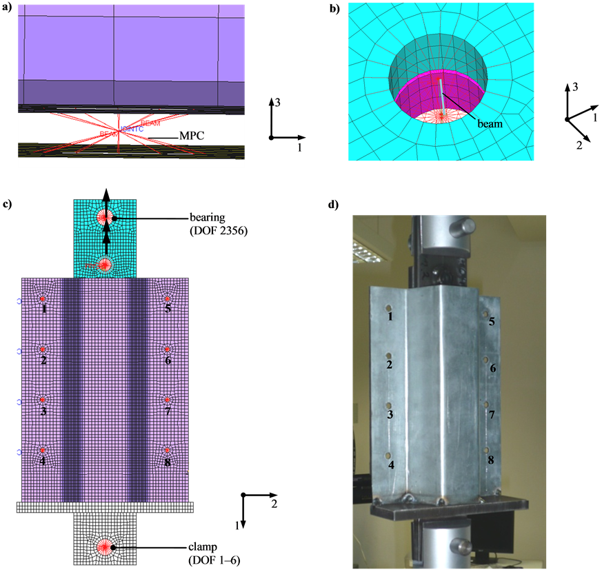
Figure 16. Joints at the generic FDJ technology demonstrator: modeling (a) of FDJ joints with MPC (red) and JOINTC element, (b) screw junction and beam elements, (c) bearing and load introduction by MPC (red) as well a FDJ joining points 1 - 8 and (d) technology demonstrator part clamped in testing machine.
was determined iteratively according Equation (4). In the further course of work critical loads—at which the computed joint failure occurred—were validated at the demonstrator test specimens (Figure 17). As shown in Figure 18, the computed joint failure corresponds to the experimentally determined data. In particular this applies to the field from medium to high shear stress. Remarkably the torsion tests have the same maxima at a preload of 2 kN and 6.0 kN. That means that at high simulated bending moments the failure criterion—according to Equation (4)—predicts overestimated failure loads. Therefore exclusive acting peel loads should be avoided, when designing FDJ joints. Consequently a more appropriate basic test for determining critical peel strength has to be developed in the course of the further work.
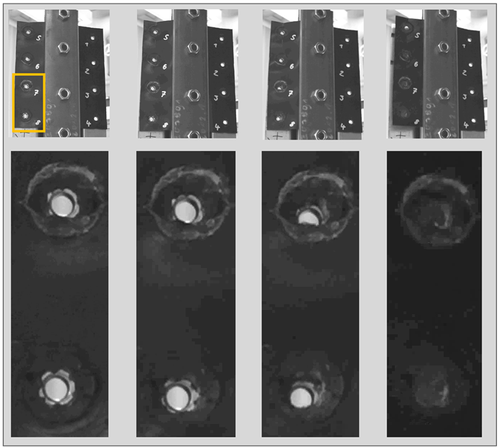
Figure 17. Failure behavior of FDJ joints when testing the generic demonstrator part.
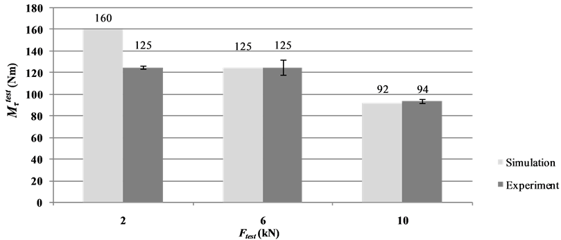
Figure 18. Comparison of bearable torsional moments determined by simulation and experiment (Number of tested specimens: 5).
6. Summary and Outlook
The necessity of weight reduction in automotive structures for the compliance of regulated climate targets is undisputed. In many other industrial areas products and individual components need to be optimized with regard to weight, stiffness, energy consumption and production costs, too. To meet the increasing demands, materials— such as metals and thermoplastic FRP—have to be combined with regard to their specific properties. Unfortunately for joining these dissimilar materials customized solutions aren’t yet available. Rather, many of the previously used joining methods destroy the load carrying fiber structure of the FRP and reducing the strength properties of the components considerably. In addition, using auxiliary joining elements reduces the lightweight potential significant.
Combining metaland FRP-thermoforming processes, however, a suitable lightweightand material oriented method for joining these materials was developed at the Institute of Lightweight Structures of CUT. The novel joining technology is characterized by high joint strengths, short process times and the avoidance of auxiliary joining elements or extensive pretreatments.
To enable computer-aided dimensioning of such FDJ-joints, a cross-section force-related failure criterion was developed in the present article. The model can successfully predict the fundamental failure behavior at low peel stresses. For this matter, the joint-specific cross-sectional forces are evaluated by a FEM-model, based on fundamental experiments. Identifying the joint characteristics, the failure equation is adjusted to the determined tolerable loads by regression analysis.
The validation of the model was carried out on representative technology demonstrators which allowed the introduction of superimposed stress states to the individual joints. Reviewing the prediction accuracy of the failure criterion a high correlation between simulation and experiment could be ensured in general. Particularly the range of superimposed loads with medium to high proportion of shear stresses was reproduced with high accuracy.
In the case of dominant  -loads the equation showed less accuracy, wherein the joint strength was overestimated by the failure criterion. To increase the prediction accuracy in this area, the development of an improved experimental setup for the determination of the
  -plane is recommended for future studies.
To account the impact of a joint failure on the overall structure and other FDJ-joints, the failure criterion can be implemented into a degradation model by reducing the joint stiffness when reaching the critical load case.
Acknowledgements
This work was performed within the Federal Cluster of Excellence EXC 1075 “MERGE Technologies for Multifunctional Lightweight Structures” and supported by the German Research Foundation (DFG). Financial support is gratefully acknowledged.
The publication costs of this article were funded by the German Research Foundation/DFG (Geschäftszeichen INST 270/219-1) and the Chemnitz University of Technology in the funding programme Open Access Publishing.
References
- Directive 2012/27/EU of the European Parliament and of the Council of 25 October 2012 on Energy Efficiency, Amending Directives 2009/125/EC and 2010/30/EU and Repealing Directives 2004/8/EC and 2006/32/EC.
- Goede, M., Stehlin, M., Rafflenbeul, L., Kopp, G. and Beeh, E. (2009) Super Light Car—Lightweight Construction Thanks to a Multi-Material Design and Function Integration. European Transport Research Review, 1, 5-10. http://dx.doi.org/10.1007/s12544-008-0001-2
- Rosato, D.V. (2005) Reinforced Plastics Handbook. 3rd Edition, Elsevier Advanced Technology, Oxford.
- Rotheiser, J. (2009) Joining of Plastics—Handbook for Designers and Engineers. 3rd Edition, Carl Hanser Verlag, Munich.
- Collins, M.W. and Brebbia, C.A. (2006) Design and Nature II: Comparing Design in Nature with Science and Engineering. 6th Edition, WIT Press, Southampton.
- Ucsnik, S., Scheererb, M., Zarembac, S. and Pahrd, D.H. (2010) Experimental Investigation of a Novel Hybrid Metal-Composite Joining Technology. Composites Part A: Applied Science and Manufacturing, 41, 369-374. http://dx.doi.org/10.1016/j.compositesa.2009.11.003
- Ageorges, C., Ye, L. and Hou, M. (2001) Advances in Fusion Bonding Techniques for Joining Thermoplastic Matrix Composites: A Review. Composites Part A: Applied Science and Manufacturing, 32, 839-857. http://dx.doi.org/10.1016/S1359-835X(00)00166-4
- Youn, B.D., Choi, K.K., Yang, R.-J. and Gu, L. (2004) Reliability-Based Design Optimization for Crashworthiness of Vehicle Side Impact. Structural and Multidisciplinary Optimization, 26, 272-283. http://dx.doi.org/10.1007/s00158-003-0345-0
- Ouisse, M. and Cogan, S. (2010) Robust Design of Spot Welds in Automotive Structures: A Decision-Making Methodology. Mechanical Systems and Signal Processing, 24, 1172-1190.
http://dx.doi.org/10.1016/j.ymssp.2009.09.012 - Palmonella, M., Friswell, M.I., Mottershead, J.E. and Lees, A.W. (2005) Finite Element Models of Spot Welds in Structural Dynamics: Review and Updating. Computers and Structures, 83, 648-661. http://dx.doi.org/10.1016/j.compstruc.2004.11.003
- Deng, X., Chen, W. and Shi, G. (2000) Three-Dimensional Finite Element Analysis of the Mechanical Behavior of Spot Welds. Finite Elements in Analysis and Design, 35, 17-39.
http://dx.doi.org/10.1016/S0168-874X(99)00053-0 - Kroll, L., Czech, A., Ulke, L. and Müller, S. (2010) Mechanical Behaviour of Bolted Joints with Load Adapted Fibre Orientation by Variable-Axial Fibre Placement. 16th International Conference on Mechanics of Composite Materials, Riga, 24-28 May 2010, 112-117.
- Mattheck, C. (1991) Trees: The Mechanical Design. 1st Edition, Springer, Berlin.
http://dx.doi.org/10.1007/978-3-642-58207-3 - Kroll, L. (2009) Textilverstarkte Kunststoffbauteile in Funktionsintegrierender Leichtbauweise. In: Wintermantel, E. and Ha, S.-W., Medizintechnik—Life Science Engineering: Interdisziplinaritat, Biokompatibilitat, Technologien, Implantate, Diagnostik, Werkstoffe, Business, Springer, Berlin, 343-356.
- Temmen, H., Degenhardt, R. and Raible, T. (2006) Tailored Fibre Placement Optimization Tool. ICAS-Secretariat— 25th International Congress of Aeronautical Sciences, Hamburg, 3-8 September 2006, 2462-2471.
- Ghiasi, H., Fayazbakhsh, K., Pasini, D. and Lessard, L. (2010) Optimum Stacking Sequence Design of Composite Materials Part II: Variable Stiffness Design. Composite Structures, 93, 1-13.
http://dx.doi.org/10.1016/j.compstruct.2010.06.001 - Reuschel, D. and Mattheck, C. (1999) Optimization of Fiber Arrangement with CAIO (Computer Aided Internal Optimization) and Application to Tensile Samples. The 6th International Conference on Computer Aided Optimum Design of Structures OPTI 99, Orlando, 16-18 March 1999, 247-255.
- Seidlitz, H., Ulke, L. and Kroll, L. (2010) Methods and Tools for Producing a Mixed Module, Verfahren und Werkzeuge zum Herstellen einer Mischbaugruppe. German Patent No. DE 102009013265B4.
- Seidlitz, H., Kroll, L. and Ulke-Winter, L. (2011) Heavy-Duty Lightweight Structures: Force Flux-Maintaining Spot Connections. Kunststoffe International, 3, 25-28.
- Seidlitz, H., Kroll, L. and Ulke-Winter, L. (2009) Load Adjusted Joining Technology for Composite-Metal Hybrids. Methods of Artificial Intelligence, Gliwice, 18-19 November 2009, 51-52.
- Simulia (2007) Abaqus—Example Problems Manual Volume II: Other Applications and Analyses. 1st Edition, Dassault Systèmes, Vélizy-Villacoublay.
- Fang, J., Hoff, C., Holman, B., Mueller, F. and Wallerstein, D. (2000) Weld Modeling with MSC.Nastran. 2nd MSC Worldwide Automotive User Conference, Dearborn, 9-11 October 2000, 1-14.
Nomenclature
CAE: Computer Aided Engineering CSFR: Cross-Sectional Force Related DOF: Degree of Freedom E-Glass: Electric Glass FDJ: Flow Drill Joining FE : Finite Element FEA: Finite Element Analyzes FEM: Finite Element Method FRP: Fiber Reinforced Plastic HX 420 LAD: Hot-Dip Galvanized High Strength Steel MMD: Multi-Material Design MPC: Multiple Point Constraints PP: Polypropylene
NOTES

*Corresponding author.