Journal of Power and Energy Engineering
Vol.05 No.02(2017), Article ID:74303,30 pages
10.4236/jpee.2017.52004
Optimization of Power Transformer Design: Losses, Voltage Regulation and Tests
McPharlen Chipekwe Mgunda
Wright State University, Fairborn, OH, USA

Copyright © 2017 by author and Scientific Research Publishing Inc.
This work is licensed under the Creative Commons Attribution International License (CC BY 4.0).
http://creativecommons.org/licenses/by/4.0/


Received: November 30, 2016; Accepted: February 20, 2017; Published: February 23, 2017
ABSTRACT
This paper presents the design approach used in designing transformers mostly used in power supplies and power systems. The paper will cover theoretical principles applied in analyzing magnetic circuits to better understand the operation of the transformer. Since well-designed transformer is supposed to meet the specifications of the environment that it is going to be used, there is a need to confirm after the transformer is built to make sure that it is going to operate efficiently and without a failure. Therefore, this paper will also present the traditional methods used to test transformers in the industries to make sure that it will operate within the prescribed loading limits and voltages. This paper will cover the transformer losses in detail including the test methods used to calculate nameplate parameters for power transformers used in power systems.
Keywords:
TTR, Hysteresis Loss, Eddy Current, Fringing Factor, Curie Temperature

1. Introduction
There are some similarities between electric circuit and magnetic circuit. Magnetic flux faces opposition due to reluctance of magnetic material while electric current flow faces opposition due to the resistance of the circuit. Both magnetic flux and electric current require driving forces, thus magnetomotive force in magnetic circuit and voltage in electric circuit.
Transformer is one of the components mostly used in electrical and electronic systems. Transformers are classified based on their application. For example, in electronic industries, the transformers can be classified in two main categories, thus low frequency transformers and high frequency transformers. There are also classified according to their use, for example, impedance matching transformers, voltage transformers and current transformers.
Impedance matching transformers are commonly used in electronic circuits. Their main purpose is to make sure that there is maximum power transfer from one stage of the circuit to the final stage. Therefore, their design approaches are based on the impedances of the electronic device; for example, audio power amplifier and speaker, their principal of operation is to maintain the same value of impedance on the output of one stage of the circuit to the input of another stage of the circuit. Thus
 (1.1.1)
Therefore, their turn’s ratio can be calculated as follows,
 (1.1.2)
Current transformers are commonly used in power systems for metering and protection. Their main purpose is to step down current levels proportionally to the primary current of power systems. Most of the devices for metering and protection relays operate on low currents. Both utility distribution and transmission systems operate on very high currents. It is therefore for this reason that you need current transformers to step down the currents.
Voltage transformers are commonly used in electronics system’s power supplies and power system’s substations. Their main purpose is to transform the voltages from one level to another. Voltage transformers are mainly classified as step-up transformers and step-down transformers. The design work in this paper covers mainly the voltage transformers. The relationship of turns-ration, current and voltages for the transformer is as shown in the equations below
 (1.1.3)
where  and
and  are primary and secondary windings;
  and
and  are primary and secondary voltages;
  and
and  are primary and secondary currents respectively.
1.1. Magnetism
Understanding of the principles of magnetism led to a major breakthrough in transformer design. Hans Christian Oersted discovered that current flowing in the conductor produces magnetic field. This discovery helped Andre’-Marie Ampere to come up with an idea that material magnetism results from localized currents [1] . Ampere observed that multiple numbers of small current loops oriented appropriately induced magnetic fields associated with magnetic materials and permanent magnets [2] .
1.2. Magnetic Materials
Transformer cores are made from materials with low reluctance to the flow of magnetic flux. Transformer cores are supposed to give easiness to the flow of magnetic flux. Magnetic material can be described as soft materials when it can easily be magnetized and demagnetized. Hard magnetic materials are those which cannot be easily magnetized and demagnetized [1] .
Magnetic material is one of the most important parts of the transformer. The transformer cores are constructed from magnetic materials. There are different types of magnetic materials. Transformer Design Engineers are therefore supposed to know the properties of different types of magnetic materials.
Iron is the most common material used in core construction. In some cases, small amount of silicon is added to iron in order to improve magnetic properties which reduce core losses [2] . Other materials used in core construction are: nickel, cobalt and iron alloys (permalloys) and iron oxides (ferrites). These materials are classified in a group of ferromagnetic materials [2] .
In summary, magnetic cores have the following properties, which need to be considered when making a decision for selecting core material for a specific transformer design: resistivity, relative permeability, saturation flux density, Hysteresis and Eddy current losses per unit volume, Curie temperature and upper operating frequency [1] .
2. Magnetic Theory
Since transformers work on the principles of magnetism, it is therefore important that this paper must introduce theoretical analysis of electro-magnetism. Magnetic theory plays a vital role in transformer design.
2.1. Ampere’s Law
Ampere discovery proved that a varying current,  flowing through a conductor created a varying magnetic field,
  around that conductor [2] . Ampere’s law is then summarized using the formula which presents the parameters of the closed loop [2] .
 (2.1.1)
dI is the vector length in the direction of the path, J is the current density, S is the surface where current I is flowing, and  is enclosed current in the path C [2] .
If a coil has N turns and the current flowing through it is I, then ampere’s Law can be applied to the coil using the formula:
 (2.1.2)
2.2. Farady’s Law
This law states that a time varying magnetic flux flowing through a closed loop generates voltage in that loop [2] .
 (2.2.1)
where λ is flux linkage, N is the number of turns of the coil,  is magnetic flux,
 is reluctance of magnetic circuit and L is the inductance of the coil and
  is the current. The formula can further be substituted by flux density, magnetic field intensity and permeability as follows:
 (2.2.2)
According to Faraday’s Law, flux density is dependent to the applied voltage to the primary winding. The volt-seconds,  applied to the primary winding for half cycle [1] ;
 (2.2.3)
The change in the flux value in the magnetic core will be;
 (2.2.4)
Therefore, to achieve the required change in flux density, the number of turns of primary winding must be;
 (2.2.5)
The current in the inductor at a given specific time can be represented by the formula:
 (2.2.6)
2.3. Lenz’s Law
This is another important law in magnetic circuits. Lenz noted that the voltage created by a time-varying magnetic flux had a direction that induced periodic current in the closed loop which also induced magnetic flux that opposed the change in the initial flux. Increasing the initial magnetic flux the induced current creates flux which opposes the increase of the initial flux and vice-versa [2] .
3. Magnetic Circuit
Magnetic circuit is somehow analogous to electric circuit. While as electric circuit needs voltage to force current flow in a closed circuit, magnetic circuit requires magneto-motive force (mmf) to cause magnetic flux flow in magnetic circuit. Electrical circuit faces an opposition to a current flow due to the resistances of the circuit, while in a magnetic circuit magnetic flux faces opposition due to the reluctance of the magnetic core and air gap. Figure 1 shows a simple two winding transformer with a core having an air gap.
Figure 2 shows a simple magnetic circuit of the transformer in Figure 1. Notice that the reluctance of the magnetic core is in series with the reluctance of the air gap. Practically the air gap has a very high reluctance despite the very small length in the gap.
From the circuit diagram in Figure 2, Rc is core reluctance, Rg is the air gag reluctance and  is magnetic flux.
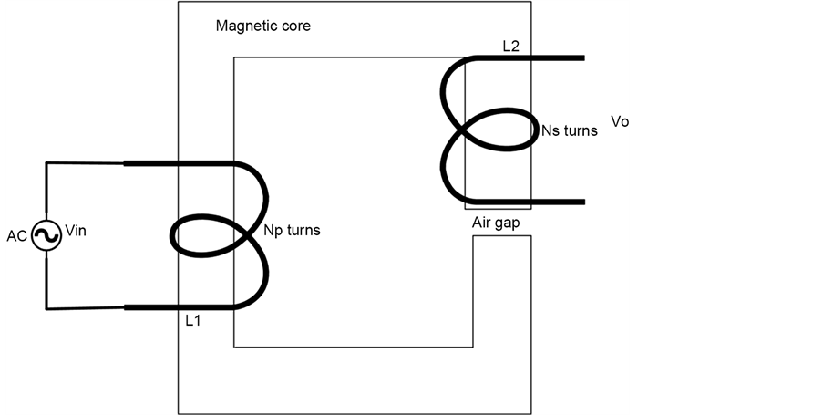
Figure 1. Two winding transformer with air-gap.
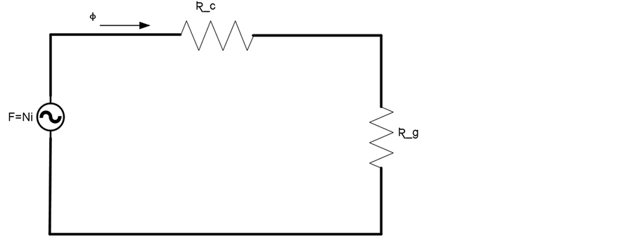
Figure 2. Magnetic circuit of two winding transformer.
3.1. Magnetomotive Force (mmf)
Magnetic circuit requires a source of energy to create a flow of magnetic flux in the magnetic circuit. Magneto-motive force,  is the source of that energy which makes magnetic flux to flow in the magnetic circuit. Magneto-motive force is created by current flowing in the coil. Magneto-motive force is directly proportional to the current flowing in the coil and the number of turns of the coil.
 (3.1.1)
The unit used to measure mmf is “A.turns”. Increasing either current or number of turns will increase the mmf which in return will increase the flow of magnetic flux in magnetic circuit.
3.2. Magnetic Flux
As stated earlier, magnetic flux in the magnetic circuit is analogous to the current flowing in electrical circuit. Magnetic flux on the surface area of “s” is given by [2]
 (3.2.1)
where “B” is flux per unit area.
The unit used to measure magnetic flux is “weber (wb)”.
3.3. Magnetic Field Intensity
Magneto-motive force of the coil can be defined as per unit length of the coil. This type of measure is described as magnetic field intensity, H. The unit used to measure magnetic field intensity is “Amps per meter, (A/m)”. Therefore, H can be presented by a formula:
 (3.3.1)
where  the length of the coil in meters, N is the number of turns of the coil and
  is the current flowing in the coil.
3.4. Magnetic Flux Density
Magnetic flux density is analogous to current density in electrical circuit. It is the amount of magnetic flux per unit cross-sectional area. Magnetic flux density can be calculated as follows:
 (3.4.1)
where,  is the total flux in magnetic circuit and A is the cross-sectional area of magnetic path.
Magnetic flux can also be calculated in relation to magnetic field intensity;
 (3.4.2)
 (3.4.3)
 (3.4.4)
where,  is permeability of free space and
  is the relative permeability.
As the current is increased in the coil, the flux density in the core increases exponentially. The rate of the increase in flux density in the core is very small when a current is increased up to a certain specified value. The core goes into saturation. The flux density is said to reach its saturation point, . Therefore, the flux at saturation point is,
 (3.4.5)
3.5. Magnetic Flux Linkage
It is the sum of flux enclosed by individual turn of wound around the magnetic core [2] . Flux linkage,  can be presented by the formulas below;
 (3.5.1)
Note that the unit for flux linkage is Volt-second.
3.6. Reluctance and Permeability
Magnetic circuit has some opposition to the flow of magnetic flux the same way it is with resistance in the electrical circuit. The opposition to magnetic flux flow in the magnetic circuit is call reluctance, . The easiness of magnetic flux to flow in a magnetic circuit is called permeance, P which is analogous to conductivity in electrical circuit. Reluctance has, therefore an inverse relationship to the magnetic material permeability and cross-sectional area of the magnetic path. Reluctance is also directly proportional to the length of magnetic circuit.
Thus, reluctance of magnetic circuit can be calculated by [2] :
 (3.6.1)
where  is magnetic core length,
  is cross-sectional area of the core, P permeance of magnetic circuit. The unit for reluctance is “turns per Henry, (turns/H)”.
Based on the formula for reluctance, we can drive the formula for permeance as follows;
 (3.6.2)
The unit for permeance is “Henry per turns, (H/turns)”.
We can also drive formulas from for magnetic flux from Equations (3.6.1) and (3.6.2), thus:
 (3.6.3)
The magnetic core inductance, L can then be calculated using reluctance of the core.
 (3.6.4)
Therefore, inductive reactance is;
 (3.6.5)
3.7. Air Gap Reluctance
Some magnetic core may have an air gap by design or because of some joints made in laminated core. The effective cross-sectional area of the air gap is not the same as the core cross-sectional area because the magnetic flux does not take a straight path in the air gap.
Making and assumption that the cross-sectional area of an air gap is the same as that of the core; we can visualize the reluctances of the core and the air gap to be in series with each other. Therefore, the total magnetic circuit reluctance is;
 (3.7.5)
Since we made an assumption that both air gap and core have the same cross-sectional area, and then we can calculate the total reluctance of magnetic circuit using the equation;
 (3.7.6)
Note that the term in the parenthesis in Equation (3.6.6) is defined as gap factor,  [2] . Gap factor can also be defined as the ratio of the total circuit reluctance to the total reluctance of the core, thus;
 (3.7.7)
Based on the Equation (3.7.7), there is a linear relationship between the length of the air gap and the gap factor. Figure 3 shows the relationship between length of the gap and the gap factor.
From the Equation (3.7.7) we can then come up with a relationship of the core relative permeability and air gap factor called effective relative permeability, ;
;
 (3.7.8)
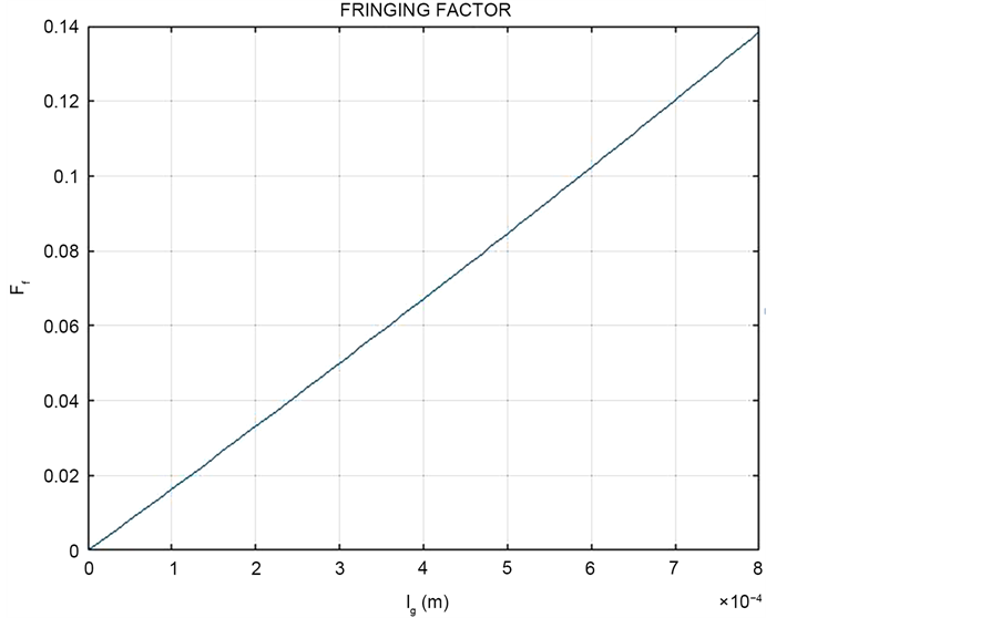
Figure 3. Relationship between changing air gap and fringing factor.
Since permeability of free space is very low, introducing an air gap reduces effective permeability of a magnetic circuit. The advantage of an air gap in a magnetic circuit is that it produces stable effective permeability and reluctance which in turn produces predictable and stable inductance [2] . Figure 4 demonstrates the relationship between the air gap and effective permeability.
The length of the gap can therefore be calculated using the equation:
 (3.7.9)
From Equation (3.6.9) we can drive the equation for inductance for the core with air gap.
 (3.7.10)
As the gap length increases, the inductance of the coil reduces as shown in Figure 5.
It must be noted that the inductance of the gap is directly proportional to the effective permeability, . As shown in Figure 4, effective permeability displays a graphical exponential decrease as the air-gap of the core increases. The same graphical exponential decrease in inductance is displayed in Figure 5 because of the aforementioned relationship between Inductance and effective permeability.
From Equation (3.7.9) we can then drive an equation to calculate the number of turns of the windings:
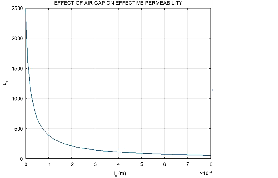
Figure 4. Effect of air gap on effective permeability of the circuit.
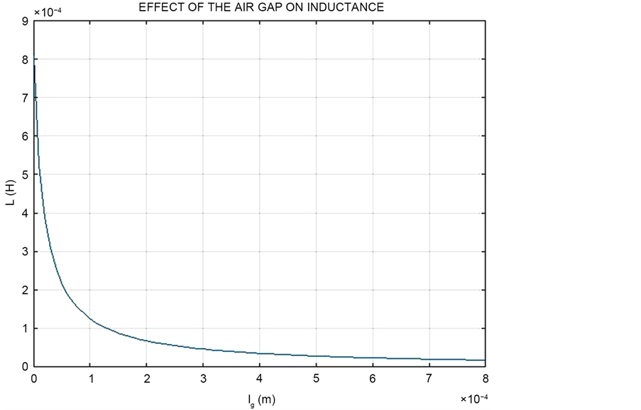
Figure 5. Effect of air gap on inductance.
 (3.7.10)
3.8. Fringing Flux
Magnetic flux lines have a tendency to repel each other when they are passing through a nonmagnetic material. When magnetic circuit has an air gap, the magnetic lines tend to bulge outwards, thus increases the cross-sectional area of the effective air gap which in returns reduces flux density [2] . The bulged magnetic flux lines in an air gap are described as fringing flux. Since the sum of fringing flux and the air gap flux must equal to the flux in the magnetic core, fringing reluctance and air gap reluctance must be viewed as being in parallel. Therefore, magnetic flux in the core is:
 (3.8.1)
where  air is gap magnetic flux and
  is fringing magnetic flux.
Since fringing and gap reluctances are in parallel and in series with core reluctances, total magnetic circuit reluctance can be presented by an equation:
 (3.8.2)
But
 (3.8.3)
 (3.8.4)
 (3.8.5)
Substituting Equation (3.8.2) with Equations (3.8.3), (3.8.4) and (3.8.5) and then factorize, we get the final equation;
 (3.8.6)
Therefore, the inductance of the magnetic circuit taking into consideration fringing effect will be [2] ;
 (3.8.7)
The ratio of the inductance of the air gap with fringing flux lines to that of without fringing flux lines is described as fringing factor, . Figure 6 shows the effect of fringing on inductance.
 (3.8.8)
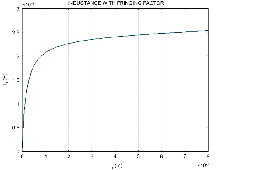
Figure 6. Effect of air gap and fringing on inductance.
Based on the Equation (3.8.7), and Equation (3.8.8) the total magnetic circuit inductance increases with an increase in air gap. Because of the increase in the inductance due to the air gap, likewise, the number of turns required will be increased too. Thus;
 (3.8.9)
To avoid saturation, the maximum number of primary windings of the transformer with air gap must be;
 (3.8.10)
4. Curie Temperature, Tc
Temperature changes have an effect on magnetic material. Spin alignment of atoms in a magnetic material causes magnetization. There is disintegration of ferromagnetic domains in a magnetic material when a temperature is above specified critical temperature called Curie temperature. When this temperature is passed, the ferromagnetic characteristics of the material changes and adopts paramagnetic characteristics with relative permeability,  [2] . Currie temperature is crucial when designing transformers which will be used in high temperature environment. Selection of core material of high Curie temperature can help to solve the problem.
The change in permeability per unit change in temperature is defined as Temperature Coefficient, TC. Temperature Coefficient can be represented by the formula;
 (4.1)
(4.1)
where  is the permeability at temperature
  and
and  is the permeability at temperature T.
5. Transformer Core and Conductor Sizing Principles
The transformer core and winding conductor selections depends mainly on the VA rating of the transformer.
5.1. Skin Effect
There are also some factors which may affect the size selection of the winding conductor, like frequency due to skin effect. At very high frequency, the current flowing in the conductor has a tendency of concentrating on the surface of the conductor and not in the inner part of the conductor. The skin depth,  of a conductor with resistivity,
  is calculated by;
 (5.1.1)
Therefore, as the frequency increases, the current density on the surface of the conductor increases and the skin depth decreases [2] , thus;
 (5.1.2)
The maximum current flowing in the conductor whose current density is ;
;
 (5.1.3)
The product of  and
and  is the effective cross-sectional area of the conductor,
 .
.
The resistance of the conductor with length  is;
is;
 (5.1.4)
Both the inductive reactance and the DC resistance are the same and are proportional to the square root of frequency, .
.
The time-average power loss in winding strip of length  is [2] ;
 (5.1.5)
The inductance then can be calculated, since we have the value of inductive reactance and frequency, thus;
 (5.1.6)
The resistivity of a winding conductor is also affected by temperature. Conducting materials have a tendency to increase in resistivity due to increase in temperature. It is therefore to consider the effect of temperature on a winding more especially on transformers which will be operating at high temperatures [2] . Thus;
 (5.1.7)
where  is temperature coefficient of a conductor and
  is the resistivity of a conductor at temperature,
 .
.
5.2. Winding Conductor and Core Sizing
The size of conductor to be used in winding the transformer must be capable to curry continuous full load current at the specified operating frequency and temperature. American Wire Gauge, AWG is commonly used in industries to define the wire sizes. Using the American Wire Gauge, the diameter of the wire can be calculated using the formula [2] :
 (5.2.1)
By knowing the diameter and the length of wire we would like to use, we can therefore calculate the total DC resistance of the wire we are going to use.
 (5.2.2)
5.3. Winding Insulation
Transformer winding wire has a layer of insulation. It is therefore necessary to also calculate the thickness of the insulation since it will also occupy some space in the core window of the transformer.
It is there, the bare conductor cross-sectional area is divided by the cross- sectional area of the insulated conductor. This ratio is defined as wire insulation factor, .
.
 (5.3.1)
For a round conductor, the wire insulation factor can be calculated by;
 (5.3.2)
where  is the diameter of uninsulated conductor and
  is the thickness of the insulation.
When winding the transformer, not all space is filled with insulation and a wire. There is some are pockets within the winding. The ratio of the area filled by insulated wire to the area filled by both insulated wire and air pockets is defined as air factor .
.
 (5.3.3)
The windings of the transformer are not directly wound on the core. Most of the transformer’s windings are made on the bobbin. It is necessary to determine the area occupied by the bobbin so that it can be added to the area occupied by the windings and the air. The total volume of windings, air and bobbin will help to size the area of the window required for the windings. The ratio of the area of the bobbin window to the area of the core window is called bobbin factor,  [2] .
[2] .
 (5.3.4)
It is also important to know that not entire area of the window is used by the windings. There is always an area which is not used. The ration of the area of the window used to the total area of the core window is called window utilization factor,  [2] .
[2] .
 (5.3.5)
The product of the window area and a winding conductor are is called, area product, . Area product is also known as ferrite-copper area product [2] .
 (5.3.6)
6. Optimum Transformer Design Procedures
Transformers are supposed to be designed to meet specified load requirements, like VA rating, operating voltages, temperature conditions, vector group and phase displacement as for transformers used in power systems, and high efficiency. The designers must also consider the economic cost of the type of the transformer they design. Transformer design engineers are supposed to minimize the cost without compromising quality.
Some of the best hints to be considered when designing transformers are:
・ Consider to minimize transformer core losses.
・ Consider the operating flux density to avoid saturation.
・ Consider the operating frequency more especially on high frequency transformers.
・ Consider normal operating temperature of the transformer to avoiding overheating which may affect the life of the transformer.
6.1. Transformer Winding Wire Selection and Core Area Product
A well designed core must be able to handle the maximum load power with minimal losses. It must be able to handle the maximum current without going into saturation. More importantly, the core must be able to accommodate the windings flexibly.
Given the transformer power rating,  , peak flux density
 , and the operating frequency,
  we can calculate the number of the primary turns,
  required.
 (6.1.1)
where  for a sine wave.
The number of secondary turns can be calculated in relation to the voltage ratio and primary turns, thus;
 (6.1.2)
We can now calculate the cross-sectional area of the wire required for both primary and secondary windings;
 (6.1.3)
 (6.1.4)
where  is the current density of the type of wire selected.
The total cross-sectional area to be occupied by both primary and secondary windings can be calculated by the formula give below.
 (6.1.5)
If the current density of the primary wire is the same as secondary wire, the area product of the transformer is;
 (6.1.6)
For an ideal transformer with sinusoidal voltages and currents, .
.
Notice that as the frequency is increased the area product of a transformer reduces.
6.2. Calculation of Window Area Used by the Windings
The length of each turn of the transformer winding can be calculated from the perimeter of the core. It must also be known that each layer of the winding will have a different winding length. For a round core, the estimated length of each turn of the winding for the first layer,  is
is
 (6.2.1)
The perimeter of each following layer is increased proportionally to the diameter of the winding wire. Therefore, the length of the second layer,  of the turn is;
 (6.2.2)
where  is the diameter of the core and
  is the cross-sectional area of the primary winding wire.
The total length of the primary winding wire is;
 (6.2.3)
The total length of the secondary winding wire is;
 (6.2.4)
To minimize the margin of error, it is good to calculate the total length of each winding layer and then add them up to find the total length of the primary winding and the secondary winding.
The cross-sectional area required by primary winding:
 (6.2.5)
The cross-sectional area required by secondary winding:
 (6.2.6)
Since the total cross-sectional area assigned to all the windings is , the fraction of the area occupied by the primary windings is;
 (6.2.7)
The fraction of the area occupied by the secondary windings is
 (6.2.8)
Therefore, rearranging Equations (6.2.7) and (6.2.8);
 (6.2.9)
 (6.2.10)
7. Transformer Losses and Phase Shift
The power supplied to the transformer is not the same as the output power. Some of the input power in the transformer is lost in the transformer. Since the transformer has reactive components, there is also a phase shift between the input and output voltage. The list below is some of the causes of the transformer power loss;
・ Winding loss due to the resistance of the winding conductors.
・ Reactive loss due to the inductance of the windings and stray capacitance.
・ Eddy current loss due to the circulating currents in the transformer core.
・ Hysteresis loss due to the continuous realignment of magnetic dipoles in the core.
7.1. Transformer Power Loss Due to the Winding Resistance
Knowing the length, cross-sectional area and the type of the wire to be used in the winding, the total DC resistance of the winding can be calculated [2] .
 (7.1.1)
 (7.1.2)
We can therefore calculate the dc winding power losses in both primary and secondary windings since we know the maximum operating current of the transformer and DC resistance of the windings;
 (7.1.3)
The secondary winding DC power loss is;
 (7.1.4)
Therefore, the total DC winding power loss for the transformer is;
 (7.1.5)
For a two winding transformer;
 (7.1.6)
By substituting  in Equation (6.2.15) by Equation (6.2.16) and factorize, we get;
 (7.1.7)
The derivative of Equation (6.2.17) will give the value of  which will minimize the winding losses.
 (7.1.8)
The minimum DC winding loss occurs when:
 (7.1.9)
By substituting  in Equation (6.2.17) with the value of Equation (6.2.19);
 (7.1.10)
Substituting  in Equation (6.2.20) with Equation (6.1.1)
 (7.1.11)
As the peak flux density increases, the optimum winding losses reduce exponentially.
The minimum transformer winding losses are achieved when;
 (7.1.12)
 (7.1.13)
Figure 7 shows graphically the point where optimum transformer losses are achieved in relation to flux density.
The designer must also make sure that transformer must not be saturated when operating at normal voltage. Therefore, there must be a limit for maximum flux density. Thus the maximum flux density can be calculated by;
 (7.1.14)
where  is the effective cross-sectional area of the core.
Considering the DC components;
 (7.1.15)
7.2. Transformer Winding Capacitance
Since the windings of the transformer are insulated and that they are side by side separated by the insulation, they act like capacitors. The transformer winding
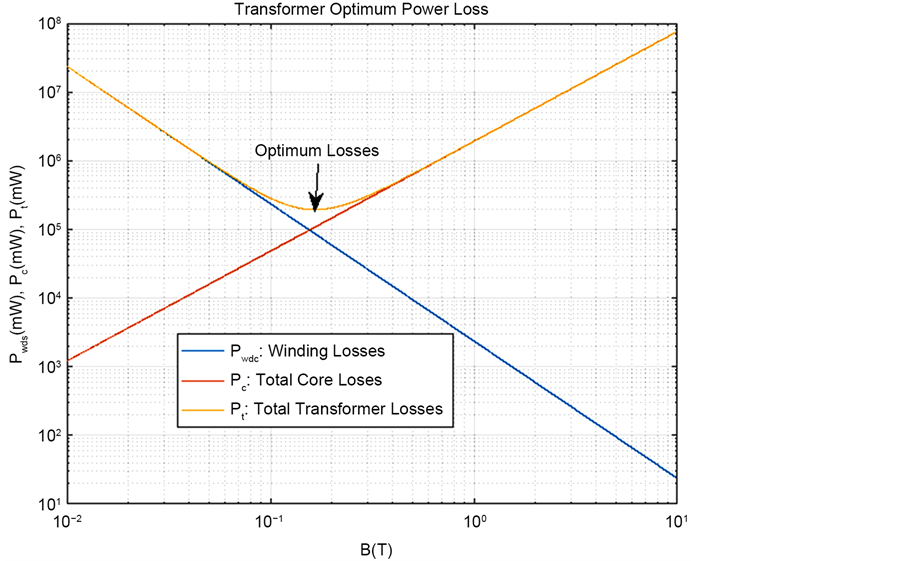
Figure 7. Optimum transformer power losses.
capacitance may have an effect on changes in voltage phase angle and may also contribute to surge phenomena during system switching [3] .
The capacitance between windings can be calculated by the formula;
 (7.2.1)
where  is permittivity through space,
  is mean diameter between two windings, H is the height of the winding,
  is the thickness of the insulation between the conductors and
  is the permittivity of the insulation.
The capacitance between cylindrical conductors and ground plane is [3]
 (7.2.2)
where R is the radius of the cylindrical conductor, H is the length of the cylindrical conductor and S is the distance of center of cylindrical conductor from the plane.
The capacitance between the primary and secondary windings is given by;
 (7.2.3)
where  is the average diameter of the winding, w is the width of the bare conductor,
  is the total thickness of the insulation.
Electrical energy stored in a capacitor is;
 (7.2.4)
For the RF transformers, resonance frequency,  is achieved when inductive reactance is equal to the capacitive reactance. Thus
 (7.2.5)
7.3. Phase Shift
The series elements like winding resistance and leakage reactance cause phase shift. The out-of-phase component of voltage drop across these series elements is usually caused by in-phase load current flowing through the leakage inductance or out-of-phase load current flowing through the winding resistance or a combination [3]
 (7.3.1)
Therefore, the transformer phase shift is;
 (7.3.2)
8. Transformer Core Losses
The main causes of the transformer core losses are eddy current and Hysteresis losses. The other losses in a transformer are stray losses which are difficult to calculate precisely due to their complexity.
8.1. Hysteresis Loss
For the core to be magnetized there is a continuous alignment and reversal of magnetic dipoles in the core material. This process requires energy hence contributes to the core loss called hysteresis loss. The hysteresis loss is frequency dependent loss. Energy lost per cycle is;
 (8.1.1)
where  is cross-sectional area of the core and
  is the length of the core.
Empirical equation (Steinmetz equation)
 (8.1.2)
where  is hysteresis loss in watts,
  (
( for a sine voltage) is a Hysteresis constant,
  is frequency in Hertz and
  is maximum flux density.
8.2. Eddy Currentlosses
Based on Faraday’s Law, changing magnetic flux induces voltage in a conducting material which in return causes current flow in that material.
 (8.2.1)
Since the core is within the vicinity of magnetic flux, there will be an induced voltage in the core which will cause current circulation in the core. This circulating current will cause power loss in the core in form of heat due to the resistance of the core. The formula for calculating Eddy current is;
 (8.2.2)
where  the cross-sectional area of the core is,
  is the resistivity of the core,
  and
and  is the frequency.
There are other transformer losses called stray losses. Some of the stray losses may be caused by some of the magnetic flux inked to the transformer tank. Stray losses in a transformer are difficult to estimate, hence this paper will only cover hysteresis and eddy current losses for the core.
Estimated total core losses will the sum of hysteresis and eddy current losses, thus.
8.3. Inductive Reactance Power
When ac voltage is applied to the windings, the magnetic fields built up in the windings. Some of the input power to the transformer is used up for this magnetic field built-up.
The magnetic field on the primary are supposed to link the secondary winding so the secondary voltage is induced in the coil. Not all the primary magnetic flux is linked to the secondary. Therefore, this also contributes to energy losses in the transformer.
 (8.3.1)
8.4. Estimated Total Core Losses
 (8.4.1)
That is,
 (8.4.2)
9. Transformer Resistive and Reactive Components Circuit Representation
Having calculated the transformer winding resistance, inductance and capacitance, they can now be represented in a transformer circuit diagram.
Where Rp is primary winding resistance, Lp is primary leakage reactance, Cp is inter-turn primary capacitance, Re is core resistance, Cw is winding to wind- ing capacitance, Ls is secondary leakage reactance, Rs is secondary winding resistance, and Cs is secondary inter-turn winding (Figure 8).
The traditional presentation of the transformer excludes the capacitance for easy calculation since it is not easy to calculate the exact values of the transformer capacitance (Figure 9).
Referred Transformer Resistance and Inductive Reactance
To calculate the total resistance and the total inductive reactance of the transformer, both the secondary resistance and inductive reactance must be referred to the primary or vise-versa (Figure 10, Figure 11).
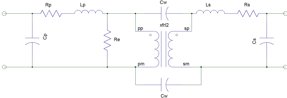
Figure 8. Transformer circuit showing resistances, capacitances and inductances.
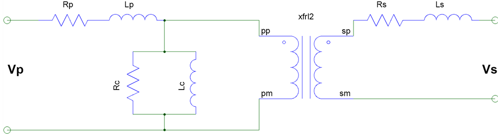
Figure 9. Transformer circuit omitting capacitive effects.
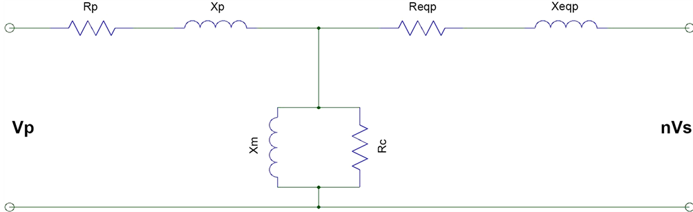
Figure 10. Showing primary impedance referred to the secondary.
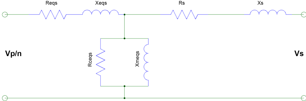
Figure 11. Showing secondary impedance referred to primary.
 (9.1.1)
 (9.1.2)
where,  , is the transformer turns ratio.
The primary impedances referred to the secondary can be translated by the formulas;
 (9.1.3)
 (9.1.4)
 (9.1.5)
 (9.1.6)
10. Voltage Regulation
As we have analyzed in chapter 6, the transformers have series impedances. Once the transformer is on load, there is a voltage drop in the transformer due to these series impedances. Therefore, the actual-] output voltage is not exactly as the one assumed to be based on the turns ratio. The actual output voltage of the transformer is therefore dependent on the load current [1] .
Calculation and Phasor Representation of Voltage Regulation
The comparison of the transformer output voltage at no load to that of full load voltage is defined as Voltage Regulation, VR.
 (10.1.1)
Applying turns ratio and transformer primary and secondary voltage relationship, we can also calculate voltage regulation as follows,
 (10.1.2)
Voltage regulation can also be represented in the formula by the total transformer impedance and the load impedance.
 (10.1.3)
It is important to have as small voltage regulation as possible. For the ideal transformer the voltage regulation, VR = 0.
The actual output voltage on the secondary transformer output terminals is
 (10.1.3)
Note that  is the voltage drop,
  due to transformer total resistance and inductive reactance.
  is the voltage measured at the output terminals of the transformer.
The phase angle displacement between input and output voltage of the transformer is;
 (10.1.4)
Figure 12 is the phasor diagram for the transformer with lagging power factor (Figure 13).
The voltage regulation is also affected by the power factor besides the loading. Figure 14 shows the variation in voltage regulation at different loads and at a specified power factor.
As shown in Figure 14, as the loading on the transformer increases, while at the same time maintaining the constant power factor, the percentage voltage
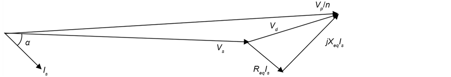
Figure 12. Phasor diagram for transformer voltages with lagging power factor.
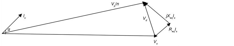
Figure 13. Phasor diagram for transformer voltages with lagging power factor.
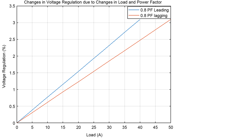
Figure 14. Effect of power factor on voltage regulation.
regulation of the transformer increases linearly. The amount of change of percentage voltage regulation differs between leading power factor and lagging power factor. The percentage voltage regulation change for a leading power factor is more than the percentage voltage regulation change for a lagging power factor for the same value of load change.
11. Transformer Efficiency
Transformer designers may also specify how good the design is based on minimum power loss. The ratio of the output power from the transformer to the input power to the transformer is defined as efficiency, .
.
 (11.1)
Since the input power to the transformer is the some of the total transformer losses and the power output, the efficiency equation can also be represented as;
 (11.2)
The total transformer losses  are caused by the following:
・ Winding losses due to winding resistances, 
・ Hysteresis losses in the transformer core.
・ Eddy current losses due to core resistance,  and the currents circulating in the core.
Note that the total output transformer
 (11.3)
Therefore, the transformer efficiency is
 (11.4)
12. Transformer Prototype Test Processes
Transformers go through different types of tests to verify that they will operate according to design specifications. This paper will discuss the more important tests all the transformers have to undergo regardless of their transformer class.
12.1. Transformer Turns Ratio Test, TTR
Transformer turns ratio test is one of the most important tests. Since there is a direct relationship between turns ratio and transformer voltage ratio, any huge era in turns ratio will be more damaging to the circuit supplied by such a transformer because the secondary voltage of the transformer will be different. Therefore, every transformer will go under TTR test after being wound. The circuit diagram in Figure 15 demonstrates how TTR test can be done.
Transformers xfmr1 and xfmr2 are both connected in parallel and are supplied by voltages Vsource. Transformer xfmr1 is the transformer under taste. Transformer xfmr2 has a known variable turns ratio.
Set the turns ratio of the transformer xfmr2 to the calculated turns ratio of the transformer xfmr1. Connect the transformers as shown in the circuit diagram in Figure 15. If the output voltages of transformers xfmr1 and xfmr2 are the same then the transformer xfmr1 is wound correctly. If the voltages are different then the transformer xfmr1 is not correctly wound.
12.2. Open Circuit Test
This test is used to measure transformer core losses. The measured values can be used to calculate the active component and reactive components of the transformer core,  and
and  respectively. Figure 16 shows how this test is set up.
In the circuit diagram, xfmr1 is the transformer under test, A is ammeter, W is wattmeter with both current and voltage probes connected to the circuit to measure active power, V is the voltmeter.
The primary rated voltage, Vin is applied to the transformer as shown in the circuit. The open circuit current in the primary,  is measured by ammeter A, open circuit voltage,
  is measured by the voltmeter V and active power
  is measured by wattmeter W. It must be noted that
  is the active core power loss [1] .
Therefore, the impedance angle is
 (12.2.1)
Open circuit impedance is
 (12.2.2)
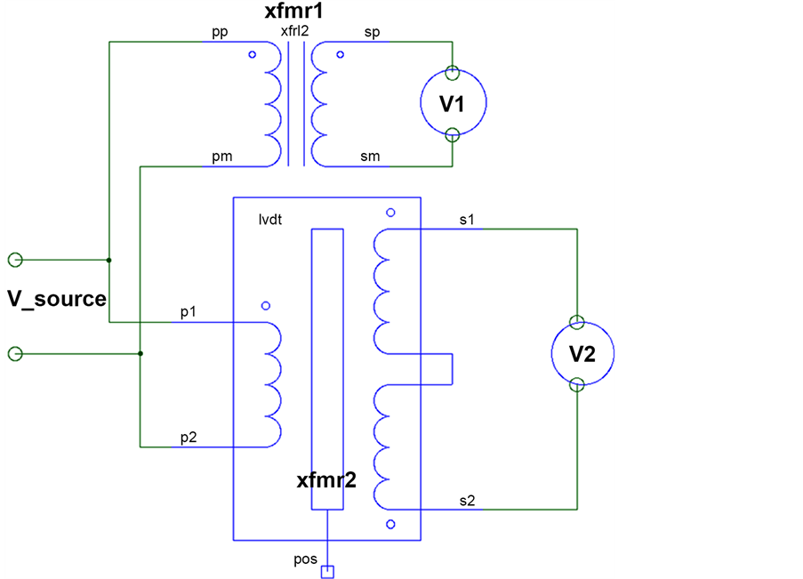
Figure 15. Transformer turns ratio test circuit.
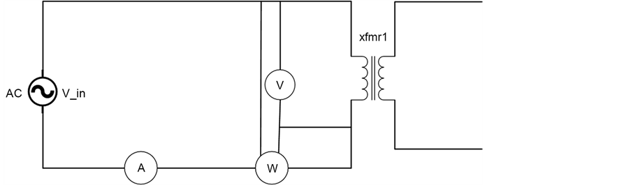
Figure 16. Open circuit test.
Therefore, we can find the values of  and
and  of the transformer core from the short circuit results. Thus
 (12.2.3)
 (12.2.4)
12.3. Short Circuit Test
This test is important because it measures the winding power losses in the transformer. The measured values of the current and voltages can be used to calculate the active and reactive components of the windings. Figure 17 shows the circuit set up of the test.
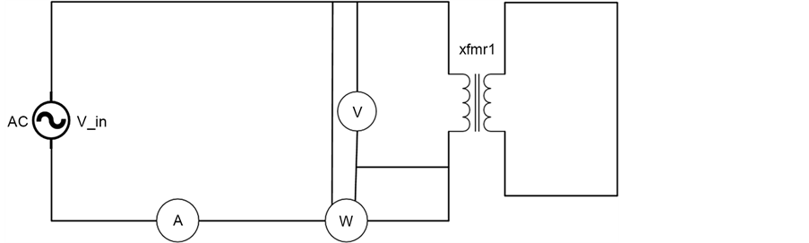
Figure 17. Short circuit test.
The input primary voltage, Vin is gradually increased from zero volts until the ammeter; “A” reading reaches the maximum value of the current rating of the transformer. The voltage reading,  and wattmeter reading,
  are recorded when the maximum current rating,
  is reached. The input voltage
  for the maximum current of the transformer is also recorded by voltmeter V.
The impedance angle is
 (12.3.1)
Therefore, the primary winding total impedance is
 (12.2.2)
Therefore, we can find the values of  and
and  of the primary winding of the transformer from the short circuit test results. Thus
 (12.3.3)
 (12.3.4)
We can do the same short circuit test on the secondary of the transformer to find the winding impedance, .
.
12.4. Winding Resistance Test
The chances to have the insulation of the windings scratched are high during the winding of the transformer. It is therefore necessary to measure the resistance of the winding and compare it with the calculated one. If the measured resistance is very low compared to the calculated one, then some of the turns are shorting due to the damaged winding insulation. This test is not as reliable since it uses DC voltage hence does not take into count skin deep effect. Although this test is not as accurate compared to TTR test, it is very easy to perform.
There are two main methods to measure the winding resistance. It can be measure directly using ohmmeter. The winding resistance can also be measured using voltmeter and ammeter as shown in the circuit in Figure 18.
 (12.4.1)
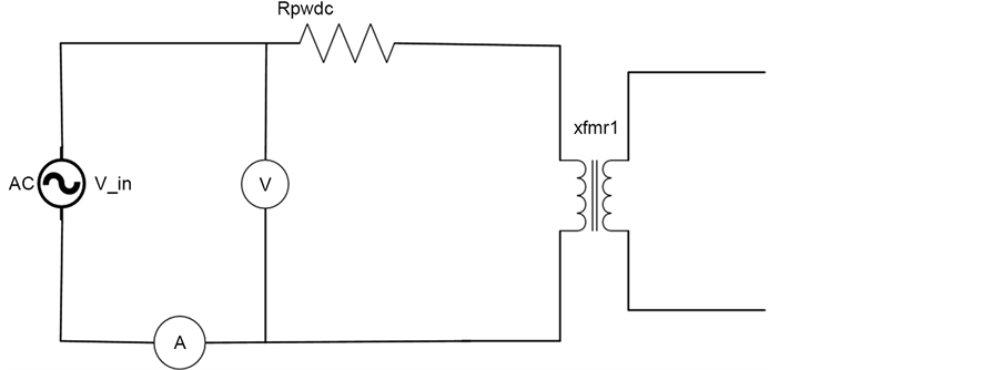
Figure 18. Circuit for winding resistance measurement.
13. Conclusions
This paper has covered the most important concepts of transformer principals which are utilized in transformer design. The chapters are listed so that the reader can easily go step-by-step to apply the technique to design her/his own transformer with a very high efficiency. Most of the designs approach used in this paper are also utilized in transformer industry.
The author has also included the most important tests for the prototype transformers. There are several tests performed by power transformer manufacturers. Most of these tests results are listed on the nameplate of the transformer. The author of this paper has just listed those tests which will help the designer to compare the calculated transformer efficiency and voltages to that of the tests results.
The graphs, circuit diagrams and phasor diagrams have been drawn using estimated transformer parameters to help visional understanding of the design concepts and calculated results of the transformer. The actual measured values will likely be different from the simulated values since some of the stray losses which have less impact on the low frequency transformer have not been considered. Some of the effects which have not been considered in the simulations are; proximity tests and winding capacitance effects. The programs which have been used for simulations and circuit drawings in this paper are; MATLAB, Saber and Visio.
Acknowledgements
The author of this paper would like to thank Dr. Marian K. Kazimierczuk, a professor in the Department of Electrical and Computer Engineering at Wright State University. The author’s knowledge in transformer design is the true reflection of the support he got from Dr. M. K. Kazimierczuk’s classroom and outside classroom time.
Cite this paper
Mgunda, M.C. (2017) Optimization of Power Transformer Design: Losses, Voltage Regulation and Tests. Journal of Power and Energy Engineering, 5, 45-74. https://doi.org/10.4236/jpee.2017.52004
References
- 1. Chapman, S.J. (1999) Electrical Machinery Fundamentals. 4th Edition, McGraw Hill Companies Inc., New York.
- 2. Kazimierczuk, M.K. (2009) High-Frequency Magnetic Components. John Wiley & Sons, Hoboken.
- 3. DelVecchio, R.M., Poulin, B., Feghali, P.T., Shah, D.M. and Ahuja, R. (2010) Transformer Design Principles. 2nd Edition, CRC Press, Boca Raton.
https://doi.org/10.1201/EBK1439805824