Journal of Power and Energy Engineering
Vol.04 No.03(2016), Article ID:65220,16 pages
10.4236/jpee.2016.43004
Comparative Analysis between Single Diode and Double Diode Model of PV Cell: Concentrate Different Parameters Effect on Its Efficiency
Tanvir Ahmad*, Sharmin Sobhan, Md. Faysal Nayan
Department of Electrical and Electronic Engineering, Ahsanullah University of Science and Technology, Dhaka, Bangladesh

Copyright © 2016 by authors and Scientific Research Publishing Inc.
This work is licensed under the Creative Commons Attribution International License (CC BY).
http://creativecommons.org/licenses/by/4.0/


Received 3 February 2016; accepted 28 March 2016; published 31 March 2016
ABSTRACT
This research appraises comparative analysis between single diode and double diode model of photovoltaic (PV) solar cells to enhance the conversion efficiency of power engendering PV solar systems. Single diode model is simple and easy to implement, whereas double diode model has better accuracy which acquiesces for more precise forecast of PV systems performance. Exploration is done on the basis of simulation results and MATLAB tool is used to serve this purpose. Simulations are performed by varying distinct model parameters such as solar irradiance, temperature, value of parasitic resistances, ideality factor of diode and number of series and parallel connected solar cells used to assemble PV array. Conspicuous demonstration is executed to analyze effects of these specifications on the efficiency curve and power vs. voltage output characteristics of PV cell for specified models.
Keywords:
Photovoltaic Cell, Single Diode Model, Double Diode Model, Efficiency, Simulation

1. Introduction
The globe gains an unbelievable supply of solar energy. The sun is an average star, a fusion reactor. It has been lighting over 4 billion years. It contributes sufficient energy in one minute to supply the world’s energy demands for one year [1] . Directly sunlight can be converted into electricity using a solar cell, which is an electronic device. Both a current and a voltage are produced from shining light on the solar cell to generate electric power [1] .
Global energy requirement and environmental issues are the compelling force for use of sustainable, alternative, and clean energy resources [2] . Solar energy is a promising renewable energy source that will contribute to secure future energy demands without emitting CO2 [3] .
A solar/PV cell is formed by fabricating a p-n junction in a thin wafer of semiconductor. These cells depend on photovoltaic effect for converting solar radiation into electricity [4] [5] . Material property of semiconductor is the reason of photovoltaic phenomena, which enables consumption of distinct type of photons from sunlight and these photons have higher energy than the band-gap energy of the semiconductor [5] . This leads to formation of a few free electron-hole pairs in the cell which are precisely proportional to input solar irradiance. The intramural electric field of p-n junction isolates these electron-hole pairs; as a result photocurrent is generated. Consequently this photocurrent is also proportional to solar radiation. Accordingly, I-V and P-V; the output characteristics of a PV cell are nonlinear and fluctuate with solar radiation, cell temperature [4] as well as other parameters of mathematical model.
Recently a new era for PV cell material has been launched with the study of perovskite, which is a mineral found in the Earth’s mantle. Researchers claim that it could be more efficient than conventional cell material by placing it on the top of traditional silicon cells. As well, it presents an economy friendly process. However, stability tests are needed to observe the water and temperature sensitivity of the material. Nevertheless, search for efficient and cost effective material for solar cell is going on [6] .
Typically, Silicon is used to assemble solar cells and an inadequate amount of power is produced by the silicon cell, because of low conversion efficiency [7] . Therefore conversion efficiency improvement study is very important for PV based power. Most crucial elements that affect the accuracy of the simulation are the PV cell modelling, which primarily associates the assessment of the efficiency curve and the non-linear I-V, P-V output characteristics curve. This paper presents a comparison between single-diode model and double-diode model of photovoltaic (PV) module to determine cell accuracy for different changing parameters. Henceforth, both models are implemented in MATLAB environment by adjusting model parameters with similar configurations.
2. Electrical Model of PV Cell
For various commercial operations, distinct types of photovoltaic (PV) cell technologies have been used. These cell technologies can be classified as multicrystalline, mono-crystalline and thin film. Single and double diode PV models have been widely used for modelling the output characteristic of a PV module [8] .
Single diode model is the simplest as it has a current source in parallel to a diode. This model is upgraded by the inclusion of one series resistance, Rs [9] - [13] . In spite of its simplicity, it exhibits acute deficiencies when suffered from temperature deviations. An accretion of the model which introduces a supplementary shunt resistance Rp [14] - [18] exhibited in Figure 1. Although momentous development is attained, this approach claims significant computing exertion. Moreover its precision declines at low irradiance, particularly in the vicinity of open circuit voltage (Voc). Two-diode model (consisting Rp and Rs) shown in Figure 2 is recommended for improved accuracy [19] .
2.1. One Diode Model
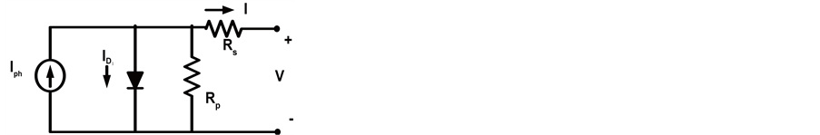
Figure 1. Electrical model of one-diode PV cell [20] - [26] .
 (1)
(1)
 (2)
(2)
 (3)
(3)
 (4)
(4)
 (5)
(5)
2.2. Double Diode Model
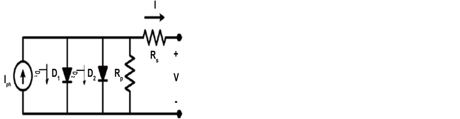
Figure 2. Electrical model of double-diode PV cell [27] - [31] .
 (6)
(6)
 (7)
(7)
 (8)
(8)
 (9)
(9)
 (10)
(10)
 (11)
(11)
2.3. Different Parameters
・ Iph is the current generated by the incident light.
・ ID1 is the Shockley diode equation due to diffusion.
・ ID2 is the Shockley diode equation due to charge recombination mechanisms.
・ I is the output Current of PV cell.
・ I01, I02 [A] are the reverse saturation current of the diodes D1 and D2 respectively.
・ q is the electron charge [1.60217646*10−19 C].
・ k is the Boltzmann constant [1.3806503*10−23 J/K].
・ T [K] is the temperature of the p-n junction.
・ a1 and a2 are ideality factor of the diodes D1 and D2 respectively for two diode model.
・ a is ideality factor of diode for one diode model.
・ VT is the thermal voltage of the module.
2.4. Efficiency
Proportion of output energy of the solar cell to input energy from the sun is described as efficiency. Simultaneously reflecting the capability of the solar cell itself, the efficiency relies upon the spectrum and intensity of the incident sunlight and the temperature of the solar cell [32] . Therefore, conditions, which are used to measure efficiency, must be regulated cautiously in order to correlate the performance of one apparatus to another. Form factor (FF) is delineated as the ratio of the maximum power output from the solar cell to the product of open circuit voltage (Voc) and short circuit current (Isc).
 (12)
(12)
 (13)
(13)
 (14)
(14)
・ VOC is open circuit voltage & ISC is the short circuit current and
・ Gn is the irradiance, Tn is the temperature, all at standard test conditions.
・ KV is the open circuit voltage temperature coefficient & KI is the short circuit current temperature coefficient. η is efficiency.
The dominant phenomena that confine cell efficiency are [33] :
Ø Reflection from the cell’s exterior.
Ø Light that is not enough dynamic to isolate electrons from their atomic bonds.
Ø Light that has excess energy beyond that required to isolate electrons from bonds.
Ø Light-produced electrons and holes (empty bonds) that casually collide with each other and recombine before they can promote to cell performance.
Ø Light-produced electrons and holes that are brought together by exterior and material blemishes in the cell.
Ø Resistance to current movement.
Ø Self-shading ensuing from upper-surface electric contacts.
Ø Performance degradation at non optimal (high or low) conducting temperatures.
3. Simulation and Observation
In order to analyze the behavior of both PV model, simulation is operated in MATLAB environment [5] [8] [34] - [36] . To compare PV models & to inspect the effect of various parameters, same specifications are used. These specifications are summarized in Table 1.

Table 1. Specifications for PV cell.
3.1. Irradiance
The efficiency of a PV appliance is contingent on the spectral distribution of the solar radiation. The Sun is a source of light and its radiation spectrum may be examined with the spectrum of a blackbody near 6000 K. Radiation of electro magnet in all wavelengths are absorbed and emitted by a black body [37] .
The study of the effect of the solar radiation on PV devices is difficult because the spectrum of the sunlight on the Earth’s outward is affected by components such as the variation of temperature on the solar disc and the impact of the ambient [38] .
 (a) (b)
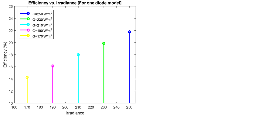
Figure 3. Different values of irradiance (G) for one diode model. (a) Efficiency vs. irradiance; (b) Output power vs. output voltage.

 (a) (b)
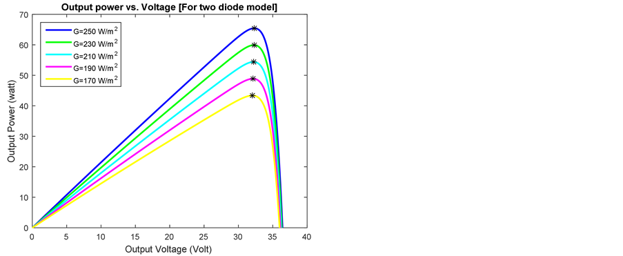
Figure 4. Different values of irradiance (G) for two diode models. (a) Efficiency vs. irradiance; (b) Output power vs. output voltage.
As demonstrate in Figure 3(b) and Figure 4(b), an increase in solar irradiance causes the power curves to move upward. Along with this, Table 2 demonstrates that maximum power and efficiency are increased at a significant amount with increasing value of solar irradiance for both models of PV cell. When irradiance is 170 watt/m2, efficiency of two diode models is 2.4% higher than one diode model. Consequently when irradiance is 250 watt/m2, efficiency of two diode models is 3.4% higher than one diode model. Hence Table 2 clearly shows that two diode models provide better efficiency.
Table 2. Efficiency & Pmax for different values of irradiance (G).
3.2. Temperature
 (a) (b)
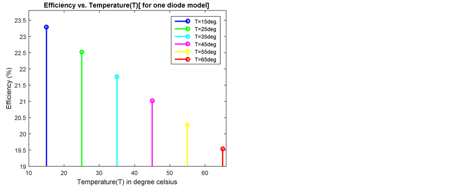
Figure 5. Different values of temperature (T) for one diode model. (a) Efficiency vs. temperature (T); (b) Output power vs. output voltage.
Increasing temperature increases the intrinsic carrier concentration. This urges the Fermi level adjacent to the intrinsic Fermi level (the middle of the band gap). Inequality between Fermi-levels of the p-type and n-type regions determines the built-in potential of a diode. As temperature increases, the Fermi level in each region shifts closer to the center of the gap, hence the built-in potential is decreased [39] [40] .

 (a) (b)
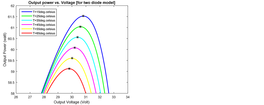
Figure 6. Different values of temperature (T) for two diode model. (a) Efficiency vs. temperature (T); (b) Output power vs. output voltage.
Table 3. Efficiency & Pmax for different values of temperature (T).
Diode’s built-in potential is relevant with the conducting voltage of a solar cell. As a solar cell gets hot, the voltage is reduced, and therefore the output power and efficiency both are reduced. Thus the performance of solar cells decreases at high temperatures. Figure 5(b) and Figure 6(b) clearly illustrate this fact for simulated mathematical models [41] .
Table 3 pageants that, at low temperature both model provide approximately same efficiency whereas at high temperature, double diode model provide better efficiency.
3.3. Shunt Resistance (Rp)
Power dissipation across internal resistances affects efficiency as well as maximum output power of solar cells. These parasitic resistances can be modelled as a parallel shunt resistance (Rp) and series resistance (RS) [42] [43] . For an ideal cell, Rp would be infinite and would not provide an alternate path for current to flow, while RS would be zero, resulting in no further voltage drop before the load.
As shunt resistance declines, current passed through it increases for a given level of junction voltage. Consequence is that the voltage-controlled portion of the I-V curve begins to sag far from the origin, producing a remarkable devaluation in the terminal current I and a minor reduction in VOC. Hence output power is reduced. Very inferior amount of Rp will attain a significant deflation in VOC. Much as in the case of a large value of series resistance, a poorly shunted solar cell will take on operating attributes analogous to those of a resistor [44] .

 (a) (b)
Figure 7. Different values of shunt resistance (Rp) for one diode model. (a) Efficiency vs. shunt resistance (Rp); (b) Output power vs. output voltage.
 (a) (b)
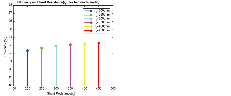
Figure 8. Different values of shunt resistance (Rp) for two diode model. (a) Efficiency vs. shunt resistance (Rp); (b) Output power vs. output voltage.
Table 4. Efficiency & Pmax for different values of shunt resistance (Rp).
PV cell efficiency as well as maximum power is increased with increasing value of shunt resistance. Figure 7 and Figure 8 expose this fact. Scrutinizing Table 4, it is examined that, PV cell efficiency will become almost constant after a certain value of shunt résistance. And this constant point occurs earlier (considering value of shunt resistance) for one diode model comparing with double diode model.
3.4. Series Resistance (Rs)
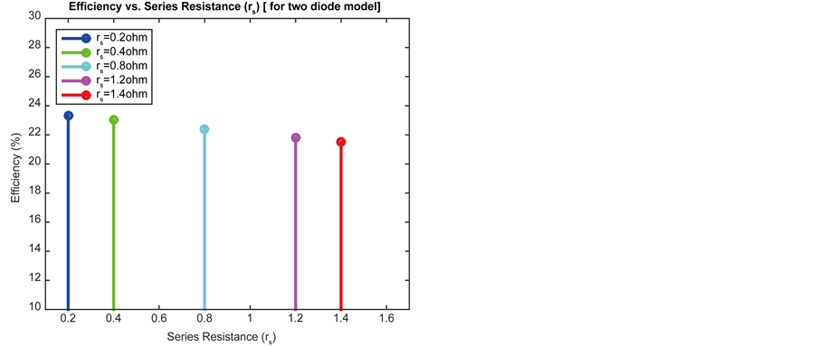
For the same amount of current, the voltage drop between the junction voltage and the terminal voltage becomes greater as series resistance increases [44] . As a result, current-controlled segment of the I-V curve initiates to sag toward the origin, causing a remarkable decrease in the terminal voltage and a minor contraction in ISC, the short-circuit current. Tremendous values of RS will also generate a significant reduction in ISC; in these regimes, series resistance governs and the behavior of the solar cell resembles that of a resistor [44] .
Inspecting Figure 9 and Figure 10, it is detected that maximum Power as well as cell efficiency reduced with increasing value of series resistance for both models. Therefore, Table 5 presents that, double diode model furnish better performance for changing values of series resistance.
3.5. Number of Series Connected Cells (Ns)
Multiple numbers of solar cells are connected to form panels. Therefore panels can be connected in series string

 (a) (b)
Figure 9. Different values of series resistance (Rs) for one diode model. (a) Efficiency vs. series resistance (Rs); (b) Output power vs. output voltage.
 (a) (b)
Figure 10. Different values of series resistance (Rs) for two diode model. (a) Efficiency vs. series resistance (Rs); (b) Output power vs. output voltage.
Table 5. Efficiency & Pmax for different values of series resistance (Rs).

 (a) (b)
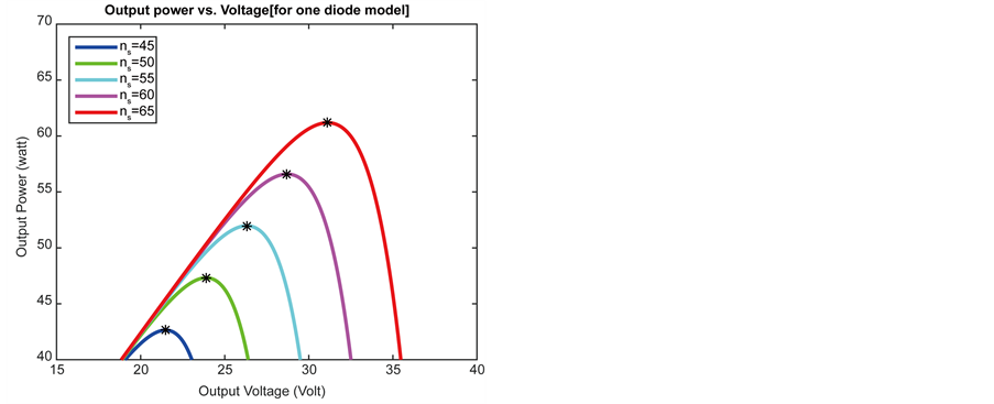
Figure 11. Different values of number of series connected cells (Ns) for one diode model. (a) Efficiency vs. number of series connected cells (Ns); (b) Output power vs. output voltage.
to increase the voltage level and in parallel to increase the current level or in a consolidation of the two. The accurate configuration depends on the current and voltage load prerequisites. Efficiency of the array can be maximized by coordinating interconnected panels in respect of their outputs [45] .
Imbalance in the short-circuit current of series connected solar cells can, contingent upon the conducting point of the module and the degree of conflict, have a severe repercussion on the PV module.
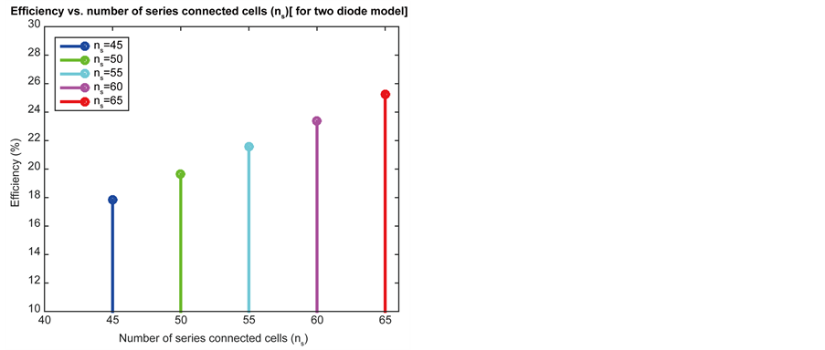
Series connections increase output power because voltage output is increased whereas output current remains almost constant. Figure 11 and Figure 12 clearly justify this fact. Efficiency of solar panel is increased with increasing number of series connected cells. For different values of series connected cell, double diode model serve with higher efficiency than single diode model. This evaluation is clearly exhibited in Table 6.
 (a) (b)
Figure 12. Different values of number of series connected cells (Ns) for two diode model. (a) Efficiency vs. number of series connected cells (Ns); (b) Output power vs. output voltage.
3.6. Parallel Connected Cells (Np)
Parallel mismatch is not an issue for small modules, because in these cases cells are connected in series. Large arrays are generated by combining modules in parallel. So conflict mostly contributes at a module level rather than at a cell level.
Table 6. Efficiency & Pmax for different values of number of series connected cells (Ns).

 (a) (b)
Figure 13. Different values of number of parallel connected cells (Np) for one diode model. (a) Efficiency vs. parallel connected cells (Np); (b) Output power vs. output voltage.

 (a) (b)
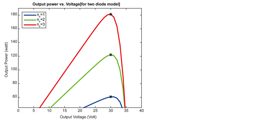
Figure 14. Different values of parallel connected cells (Np) for two diode model. (a) Efficiency vs. number of series connected cells (Ns); (b) Output power vs. output voltage.
Expanded number of parallel connected cells causes the output current to increase and the horizontal part of the I-V curve moves upward. Along with this, Figure 13(b) and Figure 14(b) show that maximum power moves upward with respective changing parameter. Also Figure 13(a) and Figure 14(a) clearly show that efficiency increased proportionally with increasing number of parallel connected cells. Similar with other parameters, two diode models contribute improved performance than either model. With percentage values of efficiency for both models shown in Table 7 confirms authenticity of this finding.
Table 7. Efficiency & Pmax for different values of parallel connected cells (Np).
3.7. Diode Ideality Factor
Ideality factor of a diode is an assessment of how intimately the diode pursues the conceptual diode equation. It is also evaluate the junction feature and the type of recombination in a solar cell [46] .
A constant value for the ideality factor is assumed for single diode equation. Practically, ideality factor is a function of voltage across the device. At high voltage, when surfaces and the bulk provinces command the recombination in the device, the ideality factor (a1) is approximately one. However the ideality factor (a2) approaches two when recombination in the junction dominates at lower voltages. The junction recombination is designed by including a second diode in parallel with the first and locating the ideality factor typically to two [47] .
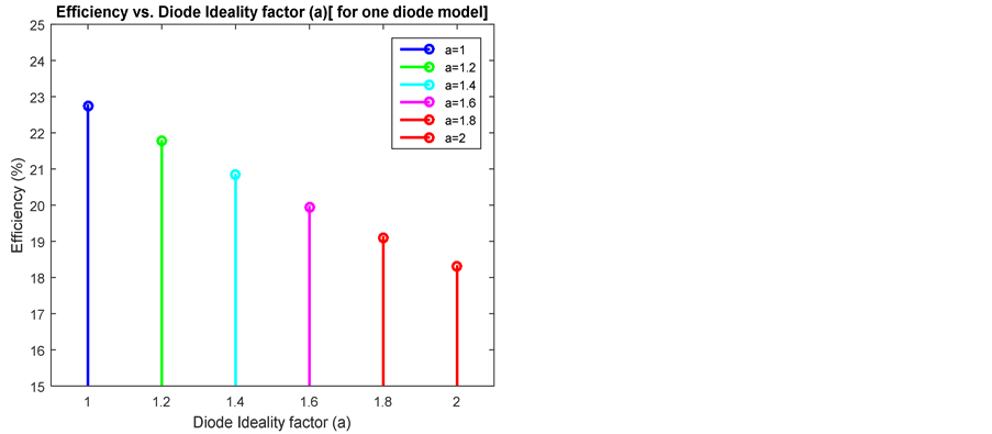
A superior value of diode ideality factor degrades the FF and efficiency for a single diode model. However it usually signals high recombination and gives low open-circuit voltages [48] . Figure 15 justifies this theoretical assumption properly.
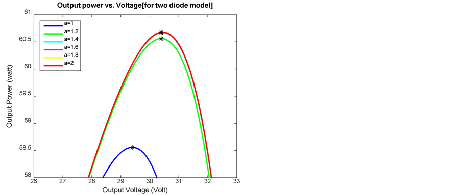
Diode ideality factors a1 and a2 respectively represent the diffusion and recombination current components for a double diode model. In accordance with Shockley’s diffusion theory, the diffusion current, a1 must be unity [49] . Nevertheless, the value of a2 is malleable. Figure 16 describes that, Pmax and efficiency are almost constant after a2 reaches the value of (1.2). Hence this will be the appropriate ideality actor for diode (D2) to have maximum cell efficiency. Table 8 validates theoretical recognitions for both models regarding diode ideality factor.
 (a) (b)
Figure 15. Different values of diode ideality factor (a) for one diode model. (a) Efficiency vs. diode ideality factor; (b) Output power vs. output voltage.

 (a) (b)
Figure 16. Different values of diode ideality factor (a2) for two diode model. (a) Efficiency vs. diode ideality factor (a2); (b) Output power vs. output voltage.
Table 8. Efficiency & Pmax for different values of diode ideality factor.
4. Concluding Remarks
Because of the large expenditure of PV modules, optimal utilization of the accessible solar energy has to be assured in PV power generation. This desires an authentic, detailed, dependable and extensive investigation of the designed scheme prior to initiation. Inclusion of the additional diode for double diode model increases model parameters. To achieve desired performance, prime challenge is to compute the values of all the model specifications. Using this MATLAB simulation-based comparative analysis, double diode model is found to contribute superior performance compared to single diode model. Accordingly selected model could be effective for professionals who require easy, understandable and accurate PV models with most desired performance to design their system. Influence of air pollutants, dirt and many other climate factors are not considered in this research. It will be appealing to investigate how these components will affect the entire energy delivered from the Sun. Additional approach specifies two-diode model by inspecting its physical attributes such as the electron diffusion coefficient, minority carrier’s lifetime, intrinsic carrier density and other semiconductor properties.
Cite this paper
Tanvir Ahmad,Sharmin Sobhan,Md. Faysal Nayan, (2016) Comparative Analysis between Single Diode and Double Diode Model of PV Cell: Concentrate Different Parameters Effect on Its Efficiency. Journal of Power and Energy Engineering,04,31-46. doi: 10.4236/jpee.2016.43004
References
- 1. Bagher, A.M., Vahid, M.M.A. and Mohsen, M. (2015) Types of Solar Cells and Application. American Journal of Optics and Photonics, 3, 94-113.
http://dx.doi.org/10.11648/j.ajop.20150305.17 - 2. Hosenuzzaman, M., Rahim, N.A., Selvaraj, J., Hasanuzzaman, M., Malek, A.B.M.A. and Nahar, A. (2015) Global Prospects, Progress, Policies, and Environmental Impact of Solar Photovoltaic Power Generation. Renewable and Sustainable Energy Reviews, 41, 284–297.
http://dx.doi.org/10.1016/j.rser.2014.08.046 - 3. Yue, C.D. and Huang, G.R. (2011) An Evaluation of Domestic Solar Energy Potential in Taiwan Incorporating Land Use Analysis. Energy Policy, 39, 7988-8002.
http://dx.doi.org/10.1016/j.enpol.2011.09.054 - 4. Tsai, H.-L., Tu, C.-S. and Su, Y.-J. (2008) Development of Generalized Photovoltaic Model Using Matlab/Simulink. Proceedings of the World Congress on Engineering and Computer Science, October 2008, 1-6.
- 5. Suthar, M., Singh, G.K. and Saini, R.P. (2013) Comparison of Mathematical Models of Photo-Voltaic (PV) Module and Effect of Various Parameters on Its Performance. 2013 International Conference on Energy Efficient Technologies for Sustainability (ICEETS), 10-12 April 2013, 1354-1359.
http://dx.doi.org/10.1109/ICEETS.2013.6533584 - 6. Senthilingam, M. (2014) A Brighter Future: Five Ideas That Will Change Solar Energy.
http://edition.cnn.com/2014/09/18/tech/innovation/solar-cells-of-the-future/ - 7. Das, N., Al Ghadeer, A. and Islam, S. (2014) Modelling and Analysis of Multi-Junction Solar Cells to Improve the Conversion Efficiency of Photovoltaic Systems. Power Engineering Conference (AUPEC), Perth, 28 September-1 October 2014, 1-5.
http://dx.doi.org/10.1109/aupec.2014.6966482 - 8. Soon, J.J., Low, K.-S. and Goh. S.T. (2014) Multi-Dimension Diode Photovoltaic (PV) Model for Different PV Cell Technologies. 2014 IEEE 23rd International Symposium on Industrial Electronics (ISIE), Istanbul, 1-4 June 2014, 2496-2501.
http://dx.doi.org/10.1109/ISIE.2014.6865012 - 9. Gow, A. and Manning, C.D. (1999) Development of a Photovoltaic Array Model for Use in Power-Electronics Simulation Studies. IEE Proceedings—Electric Power Applications, 146, 193-200.
http://dx.doi.org/10.1049/ip-epa:19990116 - 10. Gow, J.A. and Manning, C.D. (1996) Development of a Model for Photovoltaic Arrays Suitable for Use in Simulation Studies of Solar Energy Conversion Systems. Sixth International Conference on Power Electronics and Variable Speed Drives, 23-25 September 1996, 69-74.
http://dx.doi.org/10.1049/cp:19960890 - 11. Chowdhury, S., Taylor, G.A., Chowdhury, S.P., Saha, A.K. and Song, Y.H. (2007) Modeling, Simulation and Performance Analysis of a PV Array in an Embedded Environment. 42nd International Universities Power Engineering Conference, Brighton, 4-6 September 2007, 781-785.
http://dx.doi.org/10.1049/cp:19960890 - 12. Hovinen, A. (1994) Fitting of the Solar Cell/V-Curve to the Two Diode Model. Physica Scripta, T54, 175-176.
http://dx.doi.org/10.1049/cp:19960890 - 13. Hyvarinen, J. and Karila, J. (2003) New Analysis Method for Crystalline Silicon Cells. 3rd World Conference on Photovoltaic Energy Conversion, 2, 1521-1524.
- 14. Kurobe, K. and Matsunami, H. (2005) New Two-Diode Model for Detailed Analysis of Multicrystalline Silicon Solar Cells. Japanese Journal of Applied Physics, 44, 8314-8321.
http://dx.doi.org/10.1143/JJAP.44.8314 - 15. Nishioka, K., Sakitani, N., Kurobe, K., Yamamoto, Y., Ishikawa, Y., Uraoka, Y. and Fuyuki, T. (2003) Analysis of the Temperature Characteristics in Polycrystalline Si Solar Cells Using Modified Equivalent Circuit Model. Japanese Journal of Applied Physics, 42, 7175-7179.
http://dx.doi.org/10.1143/JJAP.42.7175 - 16. Nishioka, K., Sakitani, N., Uraoka, Y. and Fuyuki, T. (2007) Analysis of Multicrystalline Silicon Solar Cells by Modified 3-Diode Equivalent Circuit Model Taking Leakage Current through Periphery into Consideration. Solar Energy Materials and Solar Cells, 91, 1222-1227.
http://dx.doi.org/10.1016/j.solmat.2007.04.009 - 17. Patel, H. and Agarwal, V. (2008) MATLAB-Based Modeling to Study the Effects of Partial Shading on PV Array Characteristics. IEEE Transactions on Energy Conversion, 23, 302-310.
http://dx.doi.org/10.1109/TEC.2007.914308 - 18. Alonso-Gracia, M.C., Ruiz, J.M. and Chenlo, F. (2006) Experimental Study of Mismatch and Shading Effects. Solar Energy Materials and Solar Cells, 90, 329-340.
http://dx.doi.org/10.1016/j.solmat.2005.04.022 - 19. Kawamura, H., Naka, K., Yonekura, N., Yamanaka, S., Kawamura, H., Ohno, H. and Naito, K. (2003) Simulation of I-V Characteristics of a PV Module with Shaded PV Cells. Solar Energy Materials and Solar Cells, 75, 613-621.
http://dx.doi.org/10.1016/S0927-0248(02)00134-4 - 20. Carrero, C., Amador, J. and Arnaltes, S. (2007) A Single Procedure for Helping PV Designers to Select Silicon PV Modules and Evaluate the Loss Resistances. Renewable Energy, 32, 2579-2589.
http://dx.doi.org/10.1016/j.renene.2007.01.001 - 21. Liu, S. and Dougal, R. (2002) Dynamic Multiphysics Model for Solar Array. IEEE Transactions on Energy Conversion, 17, 285-294.
http://dx.doi.org/10.1109/TEC.2002.1009482 - 22. Yadir, S., Benhmida, M., Sidki, M., Assaid, E. and Khaidar, M. (2009) New Method for Extracting the Model Physical Parameters of Solar Cells Using Explicit Analytic Solutions of Current-Voltage Equation. 2009 International Conference on Microelectronics (ICM), Marrakech, 19-22 December 2009, 390-393.
http://dx.doi.org/10.1109/icm.2009.5418599 - 23. Aazou, S. and Assaid, E.M. (2009) Modelling Real Photovoltaic Solar Cell Using Maple. 2009 International Conference on Microelectronics (ICM), Marrakech, 19-22 December 2009, 394-397.
http://dx.doi.org/10.1109/ICM.2009.5418600 - 24. Ramos Hernanz, J., Campayo Martín, J.J., Zamora Belver, I., Larrañaga Lesaka, J., Zulueta Guerrero, E. and Puelles Pérez, E. (2010) Modelling of Photovoltaic Module. International Conference on Renewable Energies and Power Quality, Granada, 23-25 March 2010.
- 25. Ahmad, T. and Sobhan, S. (2015) Perfoemance Study of Photovoltaic Solar Cell. International Journal of Research in Engineering and Technology, 4, 12-18.
http://dx.doi.org/10.15623/ijret.2015.0410003 - 26. Nayan, M.F. and Safayet Ullah, S.M. (2015) Modelling of Solar Cell Characteristics Considering the Effect of Electrical and Environmental Parameters. 2015 3rd International Conference on Green Energy and Technology (ICGET), Dhaka, 11 September 2015, 1-6.
http://dx.doi.org/10.1109/icget.2015.7315096 - 27. Xiao, W., Dunford, W.G. and Capel, A. (2004) A Novel Modeling Method for Photovoltaic Cells. 2004 IEEE 35th Annual Power Electronics Specialists Conference, PESC 04, 3, 1950-1956.
http://dx.doi.org/10.1109/PESC.2004.1355416 - 28. Alboteanu, L., Manolea, G. and Ravigan, F. (2008) Metods of Modeling for Photovoltaic Cells. Annals of the University of Craivo, Electrical Engineering Series, No. 32.
- 29. Ishaque, K., Salam, Z. and Taheri, H. (2011) Accurate MATLAB Simulink PV System Simulator Based on a Two-Diode Model. Journal of Power Electronics, 11, 179-187.
http://dx.doi.org/10.6113/JPE.2011.11.2.179 - 30. Alsayid, B. (2012) Modeling and Simulation of Photovoltaic Cell/Module/Array with Two-Diode Model. International Journal of Computer Technology and Electronics Engineering (IJCTEE), 1, 6-11.
- 31. Salam, Z., Ishaque, K. and Taheri, H. (2010) An Improved Two-Diode Photovoltaic (PV) Model for PV System. 2010 Joint International Conference on Power Electronics, Drives and Energy Systems (PEDES) & 2010 Power India, New Delhi, 20-23 December 2010, 1-5.
http://dx.doi.org/10.1109/pedes.2010.5712374 - 32. Azim, M.I., Rahman, M.R. and Rahman, M.F. (2013) Integration of the Output of a Silicon Solar Cell to the Grid System. European Scientific Journal, 9, 261-271.
- 33. Basic Photovoltaic Principles and Methods, SERI/SP-290-1448, Solar Information Module 6213 (1982).
- 34. Villalva, M.G. and Gazoli, J.R. (2009) Comprehensive Approach to Modeling and Simulation of Photovoltaic Arrays. IEEE Transactions on Power Electronics, 24, 1198-1208.
http://dx.doi.org/10.1109/TPEL.2009.2013862 - 35. Shannan, A.A., Yahaya, N.Z. and Singh, B. (2013) Single-Diode Model and Two-Diode Model of PV Modules: A Comparison. 2013 IEEE International Conference on Control System, Computing and Engineering (ICCSCE), Mindeb, 29 November-1 December 2013, 210-214.
http://dx.doi.org/10.1109/ICCSCE.2013.6719960 - 36. Pavan Kumar, A.V., Parimi, A.M. and Rao, K.U. (2014) Performance Analysis of a Two-Diode Model of PV Cell for PV Based Generation in MATLAB. 2014 International Conference on Advanced Communication Control and Computing Technologies (ICACCCT), Ramanathapuram, 8-10 May 2014, 68-72.
http://dx.doi.org/10.1109/icaccct.2014.7019191 - 37. Guechi, A. and Chegaar, M. (2007) Effects of Diffuse Spectral Illumination on Microcrystalline Solar Cells. Journal of Electron Devices, 5, 116-121.
- 38. Villalva, M.G. and Gazoli, J.R. (2009) Comprehensive Approach to Modeling and Simulation of Photovoltaic Arrays. IEEE Transactions on Power Electronics, 24, 1198-1208.
http://dx.doi.org/10.1109/TPEL.2009.2013862 - 39.
http://electronics.stackexchange.com/ - 40. Ahmad, T., Sobhan, S. and Arif, S. (2016) MATLAB Simulation Based Efficiency Study for Two Diode Model of Photovoltaic Solar Cell l. International Journal of Engineering and Technology (IJET), 6, 28-35.
- 41. Dubey, S., Sarvaiya, J.N. and Seshadri, B. (2013) Temperature Dependent Photovoltaic (PV) Efficiency and Its Effect on PV Production in the World—A Review. Energy Procedia, 33, 311-321.
http://dx.doi.org/10.1016/j.egypro.2013.05.072 - 42. Ginley, D.S. and Cahen, D., Eds. (2011) Fundamentals of Materials for Energy and Environmental Sustainability. Cambridge University Press, Cambridge.
http://dx.doi.org/10.1017/CBO9780511718786 - 43. Abd El-Basit, W., Abd El-Maksood, A.M. and Soliman, F.A.E.-M.S. (2013) Mathematical Model for Photovoltaic Cells. Leonardo Journal of Sciences, 23, 13-28.
- 44. Yan, J. (2015) Handbook of Clean Energy Systems, 6 Volume Set. Vol. 5, John Wiley & Sons, Hoboken.
http://dx.doi.org/10.1002/9781118991978 - 45. Ramabadran, R. and Mathur, B. (2009) Matlab Based Modelling and Performance Study of Series Connected SPVA under Partial Shaded Conditions. Journal of Sustainable Development, 2, 85-94.
http://dx.doi.org/10.5539/jsd.v2n3p85 - 46. Jeng, M.-J., Lee, Y.-L. and Chang, L.-B. (2009) Temperature Dependences of InxGa1–xN Multiple Quantum Well Solar Cells. Journal of Physics D: Applied Physics, 42, Article ID: 105101.
http://dx.doi.org/10.1088/0022-3727/42/10/105101 - 47. Koirala, B.P., Sahan, B. and Henze, N. (2009) Study on MPP Mismatch Losses in Photovoltaic Applications. 24th European Photovoltaic Solar Energy Conference and Exhibition, Hamburg, 21-25 September 2009, 3727-3733.
- 48. Green, M.A. (1981) Solar Cell Fill Factors: General Graph and Empirical Expressions. Solid-State Electronics, 24, 788-789.
http://dx.doi.org/10.1016/0038-1101(81)90062-9 - 49. Sah, C., Noyce, R.N. and Shockley, W. (1957) Carrier Generation and Recombination in p-n Junctions and p-n Junction Characteristics. Proceedings of the IRE, 45, 1228-1243.
http://dx.doi.org/10.1109/JRPROC.1957.278528
NOTES

*Corresponding author.