Journal of Materials Science and Chemical Engineering
Vol.1 No.6(2013), Article ID:39491,10 pages DOI:10.4236/msce.2013.16004
The Effect of Heat Treatment Atmosphere on Hardening of Surface Region of H13 Tool Steel
Department of Mechanical Engineering, Auckland University of Technology, Auckland, New Zealand
Email: *maziar.ramezani@aut.ac.nz
Copyright © 2013 Timotius Pasang et al. This is an open access article distributed under the Creative Commons Attribution License, which permits unrestricted use, distribution, and reproduction in any medium, provided the original work is properly cited.
Received August 21, 2013; revised September 21, 2013; accepted September 28, 2013
Keywords: Carburization; H13 Tool Steel; Hardening; Heat Treatment Atmosphere; Nitriding
ABSTRACT
The main objective of the die heat treatment is to enhance the surface hardness and wear properties to extend the die service life. In this paper, a series of heat treatment experiments were conducted under different atmospheric conditions and length of treatment. Four austenitization atmospheric conditions were studied and although each heat treatment condition resulted in a different hardness profile, it did not affect the results for gas nitriding. All samples subjected to the nitriding process produced similar thicknesses of hardened case layer with average hardness of 70 - 72 HRC if the initial carbon content is not too low. It was shown that heat treatment without atmospheric control results in a lower hardness on the surface since the material was subjected to decarburization effect. The stainless steel foil wrapping around the sample and heat treatment in a vacuum furnace could restrict the decarburization process, while pack carburization heat treatment resulted in a carburization effect on the material.
1. Introduction
Heat treatment is an important process to the manufacturing industry, as the mechanical properties of metals can be improved in various ways during the process. This modification has significant influence on the performance of the die material [1]. There are different ways to perform heat treatment hardening, such as pack carburization, gas carburization, vacuum heat treatment, induction heat treatment, and salt bath [2]. Heat treatment is a process consisting of four main stages: preheat cycle, austenite formation stage, quenching and tempering. The target of heat treatment hardening is to harden the material by changing the structure from austenite structure, which is large, shape-edged, coarse and irregular structure to martensite structure, which is fine grain structure of hardened carbide.
In the world of aluminium extrusion industry, heat treatment of steel plays a major role on the determination of process efficiency and product quality. This is because the die, which is made of tool steel, must undergo a series of heat treatment processes to obtain the desired properties. As the extrusion die covers around 35% - 50% of the total manufacturing cost [3], it is essential to obtain thorough understanding on the effectiveness and the kinetics of the die heat treatment, so precise process design can be achieved with a good quality control.
Bjork et al. [4] stated the main issue of extending the service life time of extrusion die is by delaying the removal of surface layer. Surface coating technology is always applied on H13 steel as extrusion die material,to achieve better wear and corrosion resistance to counter the consequence of exposure to severe mechanical, chemical and thermal conditions during the extrusion process. Nowadays, one of the most common surface hardening technologies applied on extrusion die material is nitriding [5]. Nitriding of steel should be conducted at temperature around 500˚C to give the highest diffusion rate of nitrogen in steel [6]. Normally, the nitrated layer should not be thicker than 0.3 mm because it increases its brittleness and lowers the thermal fatigue resistance [7].
Many researches have been conducted related to the heat treatment of steel (see e.g. [8-11]); however, understanding of the decarburization during heat treatment is still limited, especially for H13 tool steel. Although Arain [12] investigated the difference between the open atmosphere heat treatment and the vacuum heat treatment, his focus was mainly on the toughness behaviour and the effect of the atmosphere condition on the hardness of the H13 tool steel is still not clear.
Although the cost of the heat treatment process is only a minor portion of the total production cost, it is arguably the most important and crucial stage on the determination of material quality. This paper investigates how the surrounding condition during heat treatment process influences the material hardness profile. The influence of carbon content of the quenched material on the response of the tempering and the performance of the nitriding is also studied. Samples of the H13 steel with specific sizes would be subjected to heat treatment process with different duration time and under different atmospheric conditions. Hardness profile of each sample would then be measured. It is also of interest to investigate the difference in effectiveness of the gas nitriding process on the samples heat treated without atmospheric control and the samples heat treated with atmospheric control. The heat treated samples would further be subjected to nitriding case hardening process with hardness profile being measured and compared.
2. Experimental Procedures
The four different heat treatment and atmospheric conditions investigated in this study are: 1) heat treatment without atmospheric control, 2) heat treatment with stainless steel foil wrapping, 3) pack carburizing heat treatment, and 4) vacuum heat treatment. Further treatment would also be conducted to investigate the effect of carbon content on the efficiency of the nitriding case hardening process. After quenching, the samples were subjected to two tempering processes followed by gas nitriding. Between each process, a sample was collected for analysis. Table 1 lists the summary of the experimental plan.
Specimens with size of 20 × 10 × 60 mm3 were cut from an H13 circular log which was provided by EXCO Limited, NZ under annealed condition, with the initial hardness of ~12 HRC. The circular log was divided into six equal sections and four of them were used for this research. Each section was dedicated to one heat treatment atmosphere condition as mentioned above. Metal strips with thickness of 10 mm were machined from each section and rectangular samples of size 7 × 10 × 60 mm3 were then sectioned from the metal strip. All specimens were then surface machined and the new specimen dimensions were then measured to ensure similar surface finish as industrial practice and to produce fairly flat surfaces for carbon diffusion modelling.
For the heat treatment without atmospheric control, the specimen was heated in a muffle furnace, at austenitizing temperature of 1020˚C for a specified time period. The samples were positioned at the centre region of the muffle furnace and were in direct contact with the surrounding atmosphere. For this atmospheric condition, carbon in steel could freely react with the ambient atmosphere. An electrical heated open atmosphere furnace (muffle furnace) was used for all heat treatment processes except vacuum heat treatment process. Data logger with a thermocouple was used to monitor and ensure the right treatment temperature was maintained during the process.
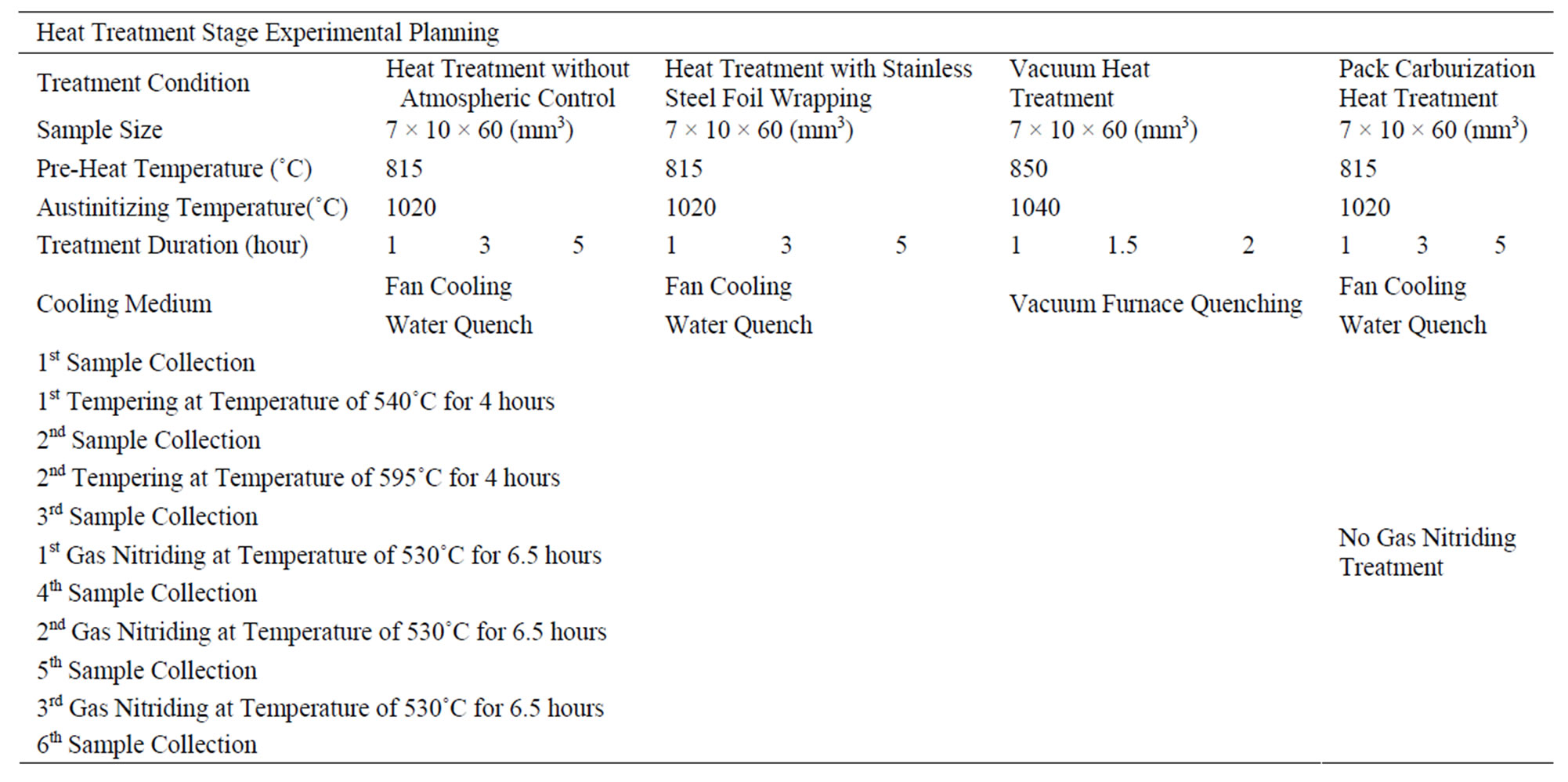
Table 1. Experiments summary.
In the heat treatment with stainless steel foil wrapping, the specimens were fully wrapped with a piece of stainless steel foil to reduce the rate of chemical diffusion between the specimen and the furnace atmosphere. This method is commonly used in industry and the suggested wrapping procedures can be found in Bryson [13]. For this research, each sample was first wrapped with the long side (the length) double folded, then double folded inwardly from the other two ends (the widths). This experiment setting aimed to minimise the continuous carbon reaction and oxidation between the sample and the ambient atmosphere by the existence of stainless steel foil. The stainless steel foil acts as a barrier to restrict the carbon reaction between the specimen and the surroundings.
In pack carburizationheat treatment, a steel box holding a specimen was fully packed with charcoal with case hardening crystal, barium salt, chemical formula of Ba(ClO3)2 and was heated to a temperature of 1020˚C. The specimen is located at the centre of the steel box and is fully covered by barium salt, so each specimen surface is in contact with the same carburized atmosphere condition.
The vacuum treatment was conducted in an Abar vacuum furnace at approximate 25 microns and preheated at temperature of 650˚C and 850˚C. Each preheating stage took 1 hour. Then it was heated up to 1040˚C and held for either 60, 90 or 120 minutes, and finally cooled to room temperature in a rate of 30˚C per minutes.
Once the austenitizing time is reached, the specimen must be rapidly cooled from the austenite state to the room temperature to form martensite. Two different cooling methods were applied with the first three atmospheric conditions, i.e. fan cooling and water quenching. For the fan cooling, the specimens were taken out from the furnace and were cooled in front of a running fan. The specimens were kept rotating so the cooling rate would be even on all surfaces. In the water quenching, the specimens were put into a pool of water, and kept stirring in the water for 2 minutes. Due to practical difficulties, the vacuum heat treated samples were only cooled in the vacuum furnace with 2 bar of nitrogen gas and the cooling rate of 30˚C/minute. After the cooling, the specimen dimensions were measured again to look for the size changes during the process. A small sample with the size of 7 × 10 × 10 mm3 was then cut from each quenched specimens for hardness test and metallographic analysis.
The remaining part of the specimens was then subjected to two tempering processes which were held at temperature of 540˚C and 595˚C respectively in a vacuum furnace for four hours. To investigate the dynamics of the carbon content on the efficiency of case hardening by gas nitriding, the last part of the remaining treated samples were cut into three different pieces and subjected to once, twice or thrice times of nitriding case hardening process. Samples from pack carburization experiment were not subjected to case hardening process because this is not a usual practice in industry. The gas nitriding process was conducted at 530˚C under controlled atmosphere for 6.5 hours.
The microhardness test method used for this research was Vicker’s hardness test and the load applied was 300 gf. Hardness measurements were conducted from the sample edge to the centre of samples, which was approximately 5000 µm from the edge using the Vicker’s microhardness machine. The hardness measurements were measured in step of 50 µm until 1000 µm, with one extra measurement at 20 µm. For regions between 1000 µm and 5000 µm, the measurements are measured in step of 250 µm. After microhardness tests, the samples would be subjected to surface polishing again and were etched with Nital solution, 3% HNO3 in ethanol. The polished surface was washed with alcohol and dried with warm air immediately after etching, to expose the microstructure details. Metallographic pictures would be taken for the measurement of the depth of the carburization/decarburization layer or the case hardening layer, and for the microstructure examination.
3. Results and Discussions
Hardness profile of each heat treatment stage, including as quenched state, the first tempered state, the second tempered state, and all of the three nitrided states are presented in this section. It must be noted that although the microhardness tests were conducted with Vicker’s measurement, during the process of analysis, the data was converted into Rockwell (HRC) scale. It is because Rockwell scale is the common scale used in steel industries.
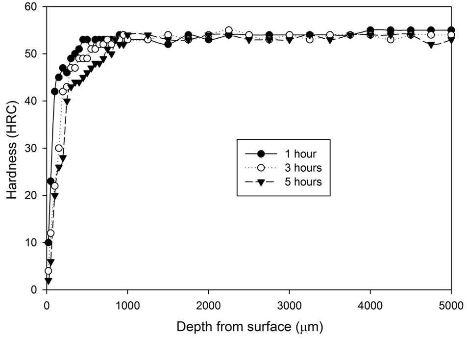
Figure 1 shows the hardness profile for all samples heat treated without atmospheric control. Hardness decrease can be found towards the surface region of all samples heat treated without any atmospheric control. The hardness at the region 100 μm underneath the surface increases progressively, then the hardness slowly increases toward the constant state. The figure shows that samples cooled by water generally have higher hardness (54 - 57 HRC) than samples cooled by fan air (53 - 54 HRC). The decarburized layer is found to be thicker as treatment time increases. Another notable difference is that the surface hardness (20 μm below sample surface) of the fan cooled samples is lower than those of the water quenched samples. The fan cooled samples had a surface hardness of 2 - 10 HRC compared to the surface hardness of 14 - 22 HRC for the water quenched samples.
Figure 2 shows the tempering characteristics of samples
 (a)
(a)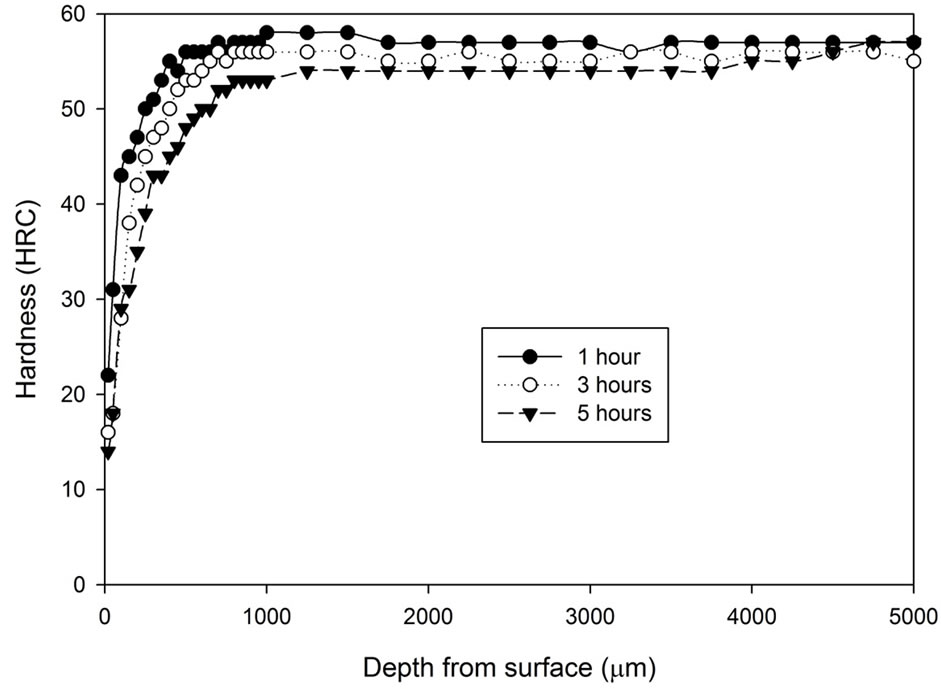 (b)
(b)
Figure 1. Hardness profiles of samples heat treated at 1020˚C in an uncontrolled atmosphere for 1, 3 and 5 hours followed by: (a) Fan cooling; (b) Water quench.
 (a)
(a)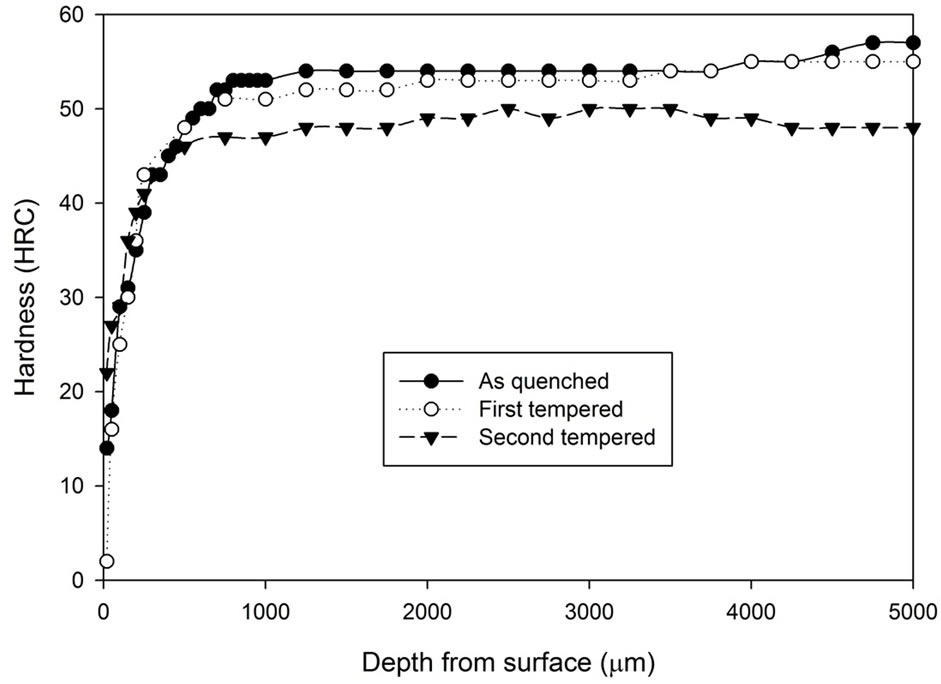 (b)
(b)
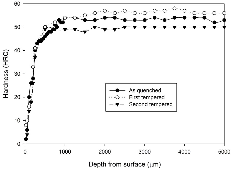
Figure 2. Comparison of hardness profiles of sample heat treated without atmospheric control at 1020˚C for 5 hours in the as quenched, first tempered and second tempered conditions: (a) Fan cooling; (b) Water quench.
after 5 hours of heat treatment without atmospheric control. It can be seen that the fan cooled specimens had hardness increase after the first tempering stage while the water quenched specimens do not show any hardness increase. However, after the second tempering stage, hardness of both fan cooled samples and water quenched samples dropped to around 46 to 48 HRC. Note that the tempering process does not appear to have any effect on the decarburising zone.
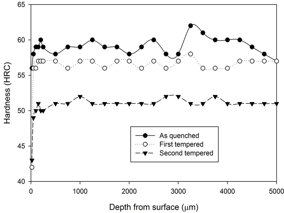
The hardness profile as shown in Figure 3 for all the samples heat treated with the stainless steel foil wrapping shows a distinct characteristic. Such heat treatment method gives a reasonably constant hardness profile throughout. Although there are variations in terms of hardness, the variations are only 1 - 2 scale points from the average value, which is acceptable in the industry. The treatment time did not seem to have any direct influence on the hardness profile. The results also show that a slight drop of the hardness can be found around 20 µm from the surface.
The hardness profiles of the tempered samples are presented in Figure 4. The graphs show that the first tempering process decreases the hardness of the as quenched samples from an average of 59 HRC to 57 HRC, while the second tempering process further decreases the hardness to around 48 - 50 HRC.
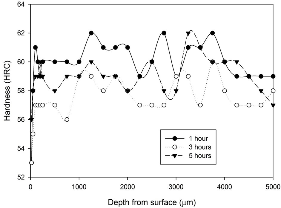
From the results shown in Figure 5, all the samples heat treated with the pack carburization experienced a hardening effect on the surface. Beyond the carburized layer, the hardness of all pack carburized samples was approximately the same. It must be noticed that the hardness at the region between 500 μm to 1000 μm was comparably lower than its core hardness for the samples heat treated for 1 hour. By studying the hardness profile of the surface region up to 500 µm from the edges, it can be seen that as the treatment time increases, the surface
 (a)
(a)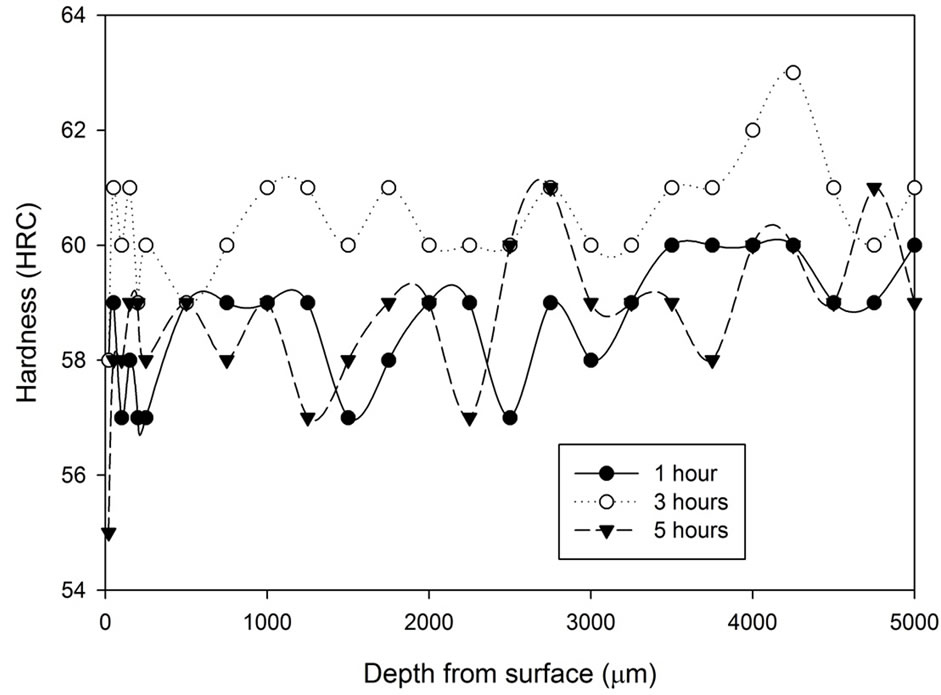 (b)
(b)
Figure 3. Hardness profiles of samples heat treated at 1020˚C with stainless steel foil wrapping for 1, 3 and 5 hours followed by: (a) Fan cooling; (b) Water quench.
 (a)
(a)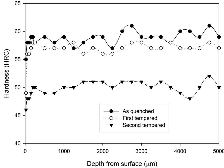 (b)
(b)
Figure 4. Comparison of hardness profiles of samples heat treated with stainless steel foil wrapping at 1020˚C for 5 hours in the as quenched, first tempered and second tempered conditions: (a) Fan cooling; (b) Water quench.
 (a)
(a)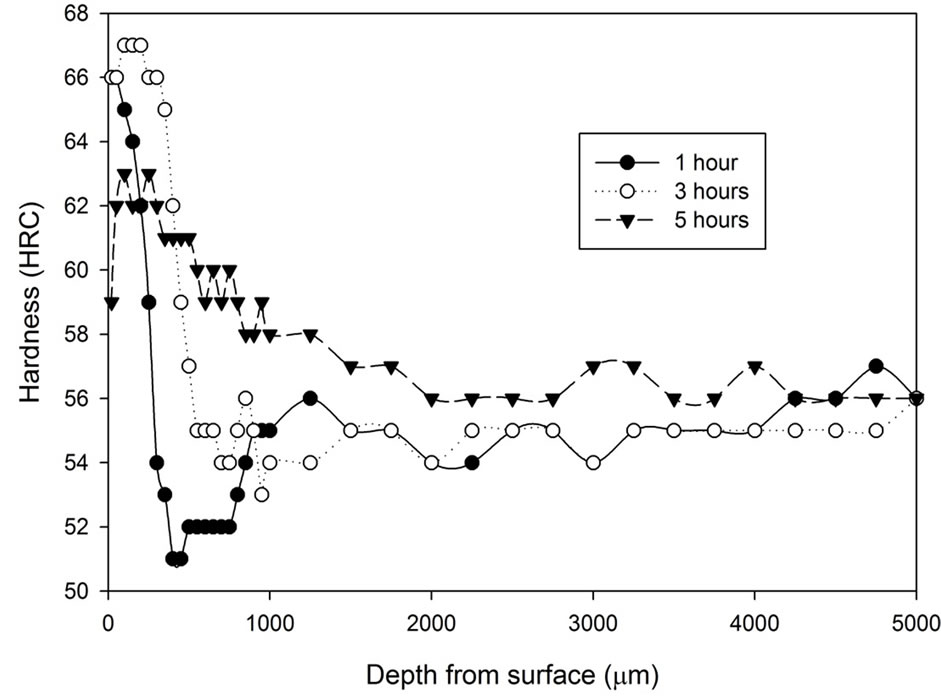 (b)
(b)
Figure 5. Hardness profiles of samples of pack carburization heat treated at 1020˚C for 1, 3 and 5 hours followed by: (a) Fan cooling; (b) Water quench.
hardness increases respectively. The graphs also show that the samples cooled by water in fact have lower surface hardness than the samples cooled by fan cooling.
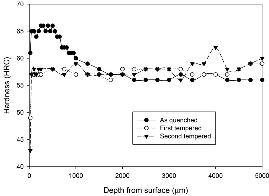
The first tempered and the second tempered hardening characteristic for the pack carburized heat treatment is shown in Figure 6. Hardness increase can be found in the carburized samples cooled by fan after the first tempering stage. The improvement in hardness after the first tempering process is especially significant at the central region of the sample and was increased from 56 HRC to 58 HRC. The second tempering stage does not show any effect on the hardness change. However, if the carburized samples were cooled by water, after the first tempering stage, secondary hardening effect can be found throughout the samples and is especially dominant at the surface region. Great amount of hardness improvement can be found at the region 1000 µm underneath the surface. After the second tempering process, the hardness profile became constant with the hardness of around 59 HRC,
 (a)
(a)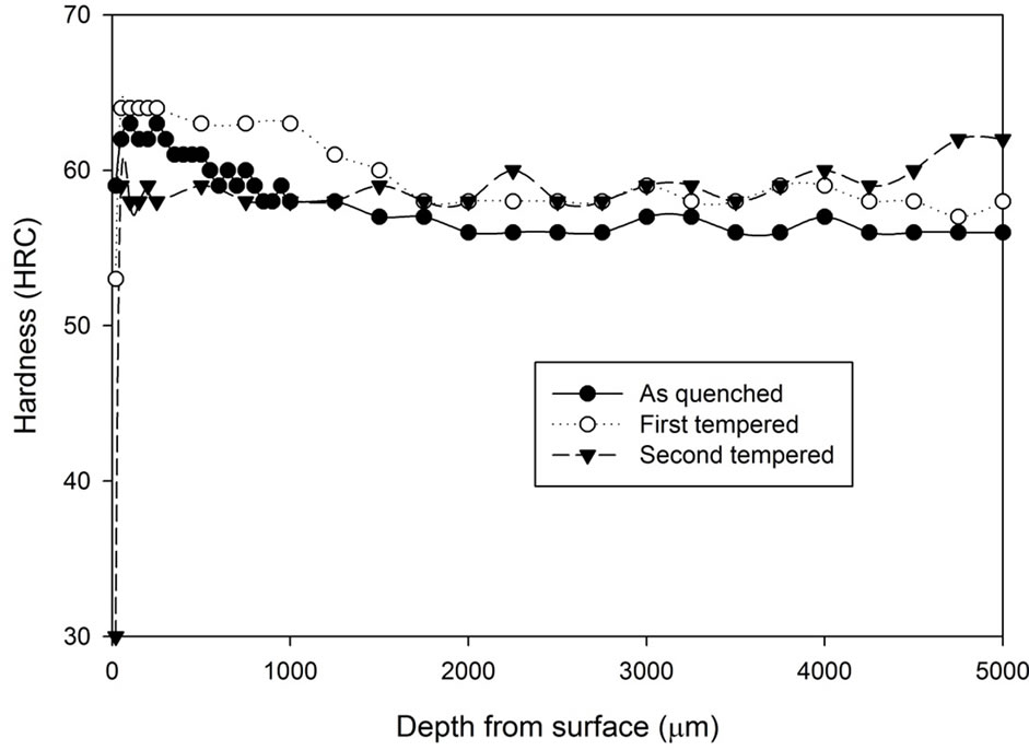 (b)
(b)
Figure 6. Comparison of hardness profiles of samples pack carburized heat treated at 1020˚C for 5 hours in the as quenched, first tempered and second tempered conditions: (a) Fan cooling; (b) Water quench.
the similar hardness as the core hardness of the first tempered condition.
As mentioned previously, the samples from the vacuum heat treatment experiments were obtained by withholding the samples in a vacuum furnace at 1040˚C for 1 hour, 1.5 hours and 2 hours followed by vacuum furnace cooling under 2 bar pressure of N2 at a rate of 30˚C /minute. As shown in Figure 7, there is no indication suggesting the time of heat treatment has remarkable effect on the hardness of the as quenched samples and the hardness profile of each sample is reasonably constant. No decarburization layer or carburization layer is found. The hardness varies one or two scale points around 57 HRC. There is only a slight indication, if any, that if the treatment duration increases, the level of hardness variation is lower.
The hardness results obtained from the first tempered and the second tempered samples are analysed and are presented in Figures 8-10. At first, all three graphs express similar characteristics. After the first tempering, the material hardness increased, and then it decreased below the as quenched hardness after the second tempered process. Comparing the three graphs, it can be concluded that the hardness variation between the first tempered stage and the second tempered stage becomes narrower as treatment time increases.
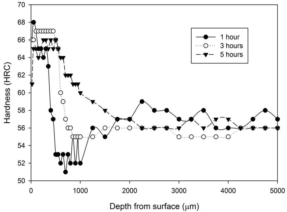
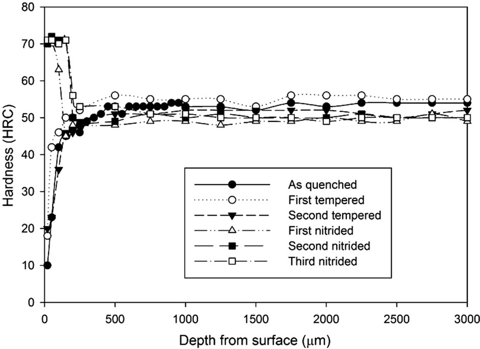
For each heat treating condition, the samples were further hardened by the gas nitriding process. The hardness profiles of each heat treated and nitrided sample are shown in Figures 11-13 according to their hardening process atmospheric conditions. Figure 11 shows that even with a decarburized layer, the nitriding process can still increase the surface hardness significantly up to a certain depth from the surface. The peak hardness is somewhere at 70 - 73 HRC. Results indicate that except for the third nitriding process, both the first nitriding and the second nitriding processes result in hardness enhancement.
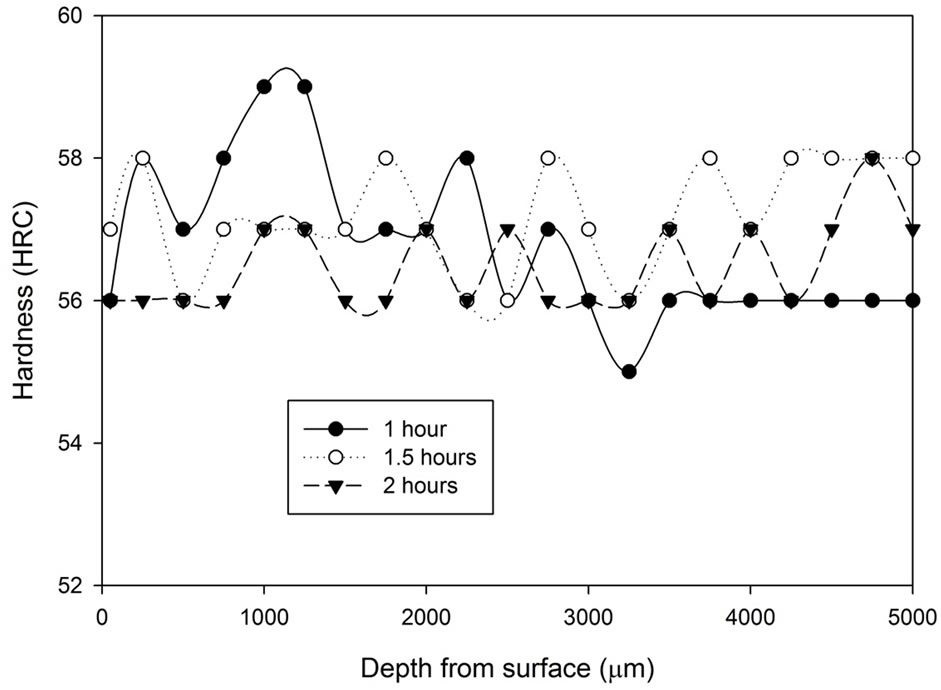
Figure 7. Hardness profiles of samples vacuum heat treated at 1, 1.5 and 2 hours followed by vacuum cooling.
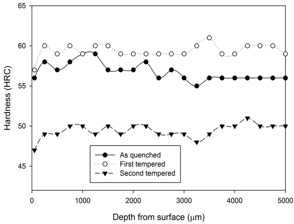
Figure 8. Comparison of hardness profiles of samples heat treated in vacuum furnace at 1040˚C for 1 hour in the as quenched, first tempered and second tempered conditions.
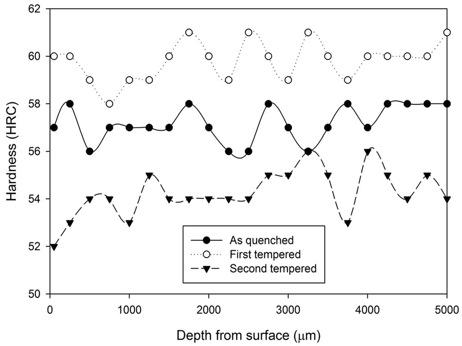
Figure 9. Comparison of hardness profiles of samples heat treated in vacuum furnace at 1040˚C for 1.5 hours in the as quenched, first tempered and second tempered conditions.
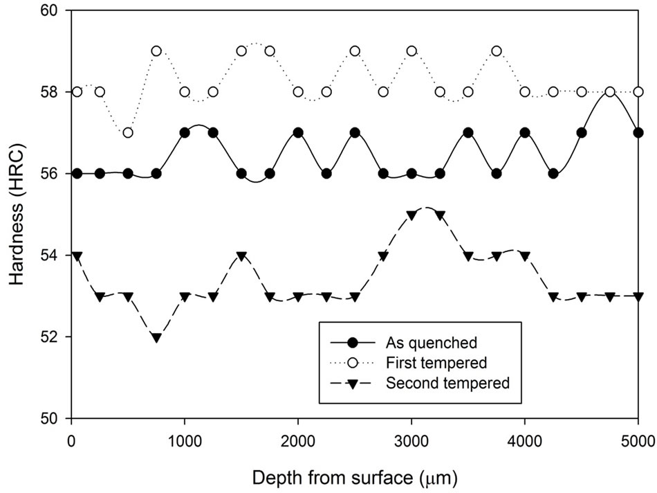
Figure 10. Comparison of hardness profiles of samples heat treated in vacuum furnace at 1040˚C for 2 hours in the as quenched, first tempered and second tempered conditions.
 (a)
(a)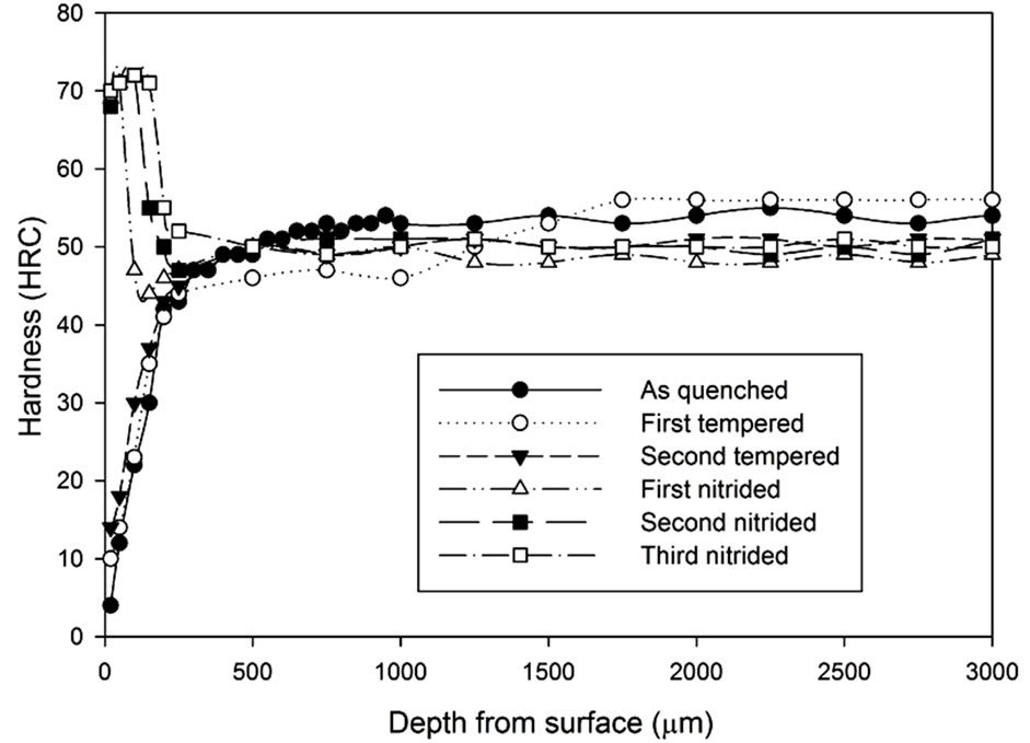 (b)
(b)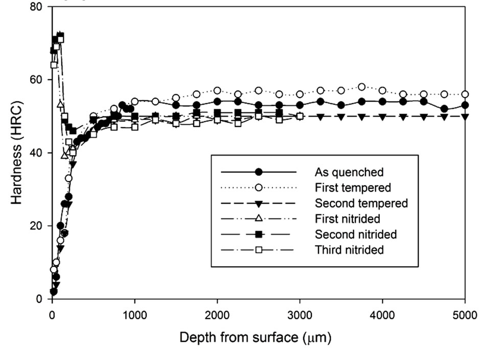 (c)
(c)
Figure 11. Hardness profiles of gas nitrided sample heat treated without atmospheric control at 1020˚C followed by fan cooling: (a) 1 hour heat treatment; (b) 3 hours heat treatment; (c) 5 hours heat treatment.
By increasing the heat treatment duration, the surface hardness (20 μm underneath the surface) became lower respectively. However, the surface hardness was increased with the number of times of nitriding process.
 (a)
(a) (b)
(b)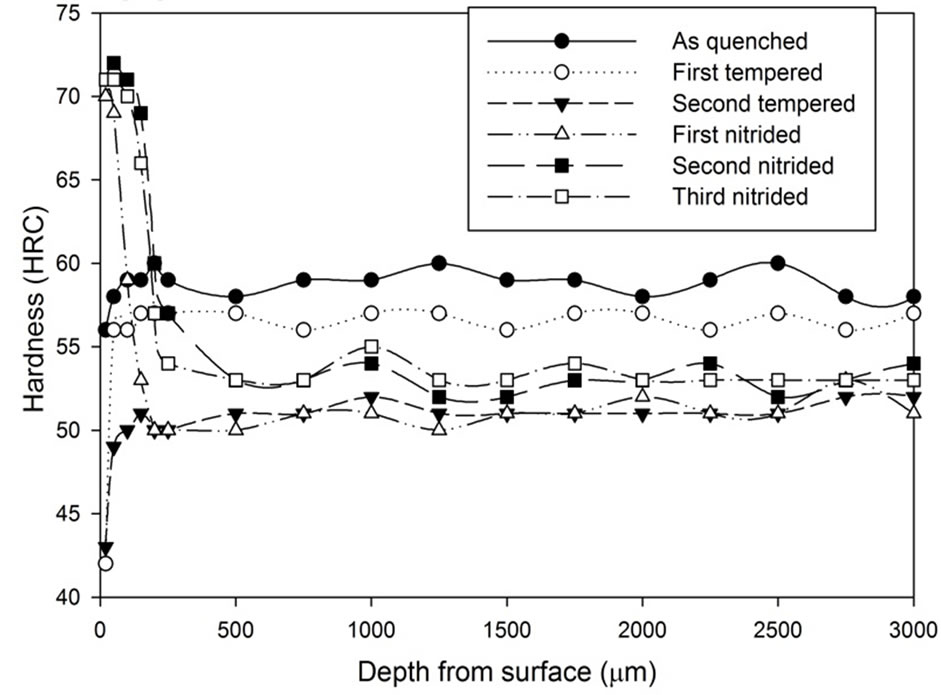 (c)
(c)
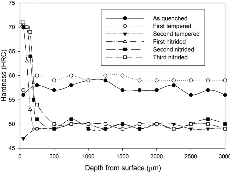
Figure 12. Hardness profiles of gas nitrided sample heat treated Stainless Steel Foil Wrapping at 1020˚C followed by fan cooling: (a) 1 hour heat treatment; (b) 3 hours heat treatment; (c) 5 hours heat treatment.
Such as the result presented in Figure 11(c), the surface hardness was increased from 55 HRC to 71 HRC after two times of extra nitriding processes.
 (a)
(a) (b)
(b)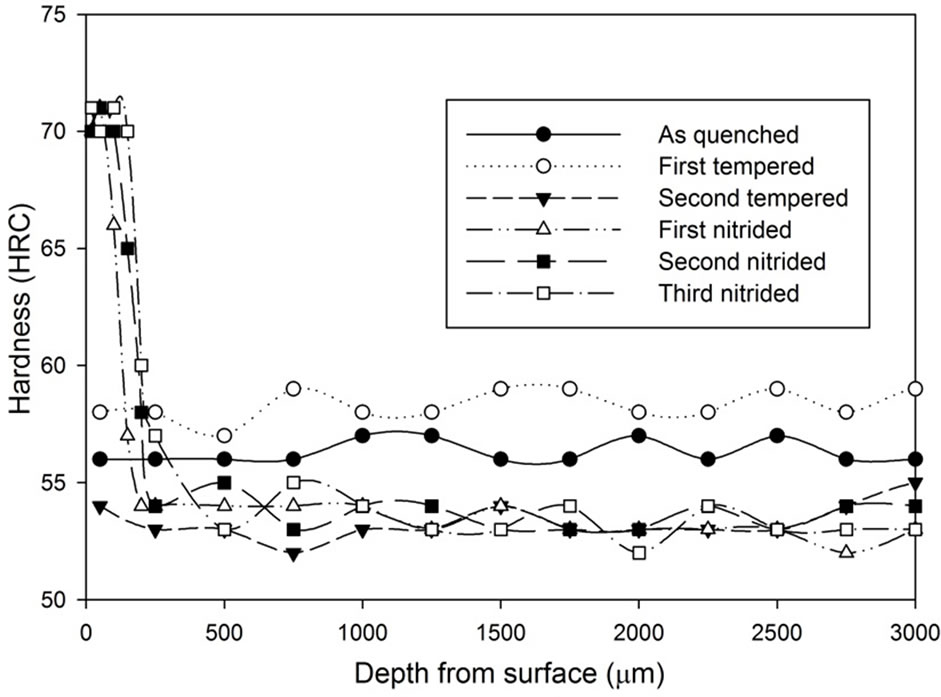 (c)
(c)
Figure 13. Hardness profiles of gas nitrided sample heat treated with vacuum furnace at 1040˚C followed by fan cooling for: (a) 1 hour heat treatment; (b) 1.5 hours heat treatment; (c) 2 hours heat treatment.
It can be seen that after the nitriding process, the hardness at the region 500 µm from the surface increased dramatically. All results show that there is an improvement on surface hardness after the nitriding process except for the third nitriding. Compared to the hardness profile of the second nitriding process, there is no indication of significant improvement in terms of hardness property for the third nitriding process. Except for the results of the 3 hours heat treatment, the core hardness of nitrided samples are around the same as the hardness of the second tempered samples.
The three graphs in Figure 12 show the increase in hardness on the surface region after the gas nitriding process was conducted. The hardened surface layer being thicker as more gas nitriding process was conducted. However, if the graphs are studied closely, they show that the hardened layer difference in thickness between the third nitrided and the second nitrided samples is smaller than the difference in thickness between the second nitrided and the first nitrided samples. Results also show the hardness below the hardened layer remains the same level as the hardness at the second tempered condition.
Results have shown that both the vacuum heat treatment and the heat treatment with the stainless steel foil wrapping produce a reasonably constant hardness profile on the as quenched samples. This suggests that the carbon neither diffuses into or out from metal substrate during austenitization. This is understandable for treatment in vacuum furnace because carburization cannot be initiated due to the absence of the carbon monoxide. Neither can decarburization proceed because the oxide layer cannot be formed in the vacuum condition. For heat treatment with stainless steel foil wrapping without continuous supply of carbon dioxide, it is believed the samples were in decarburization during austenitization. This can be supported by the drop in hardness at 20 µm underneath the samples surface. However, with the negligible amount of carbon dioxide inside the wrapping, the decarburization process reaches equilibrium after a short period of time.
Although both the vacuum heat treatment and the heat treatment with stainless steel foil wrapping are able to prevent the decarburizaiton process, they perform different tempering characteristic to each other. In the vacuum heat treatment process, secondary hardening can be found after the first temper stage and between the tempering temperature of 500˚C and 550˚C, a secondary hardening effect was founded. This secondary hardening effect is the fourth stage of the tempering process.
After the gas nitriding, all samples present peak hardness within 70 - 73 HRC. However, significant hardness decrease was found on the surface (20 μm underneath the surface) for samples heat treated without atmospheric control. The slight drop in the surface hardness can also be found in samples heat treated with stainless steel foil wrapping. From the above observations, this suggests that the performance of gas nitriding process is independent of the initial carbon content if it is not too low in value.
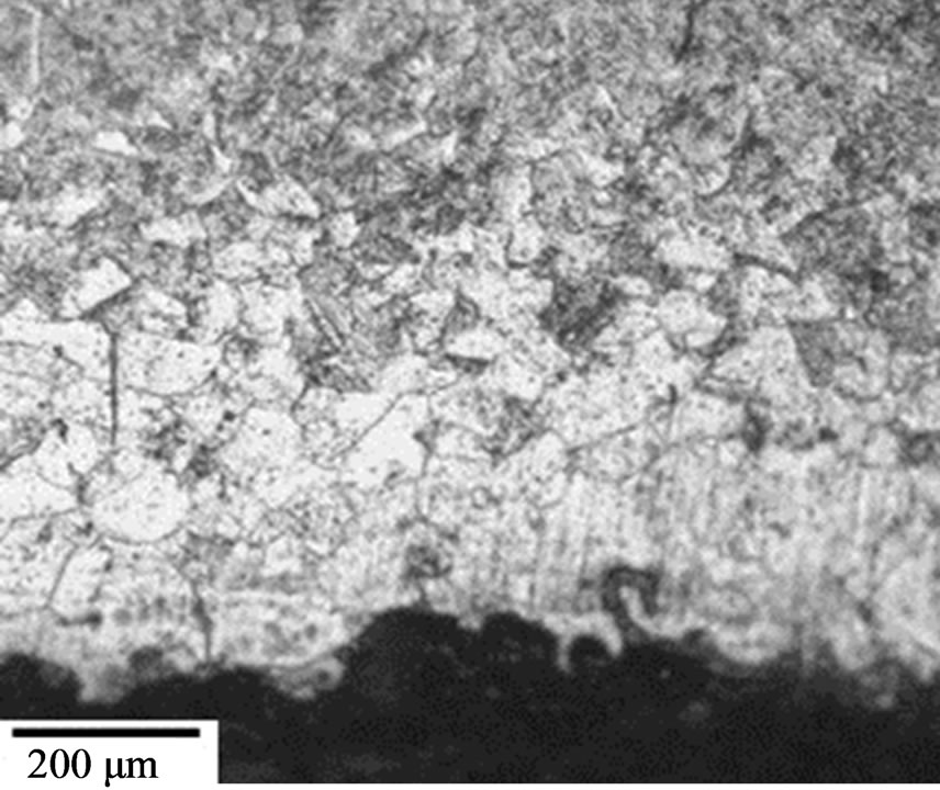
Moreover, similar thickness of hardened layer was produced no matter which austenitizing atmospheric condition the sample experienced. All samples have the hardened case thickness of ~0.15 mm after the first nitriding process. The hardened case thickness was then increased to ~0.25 mm after the second nitriding process. However, the third nitriding process does not provide any significant hardened case thickness improvement for all samples. For each individual heat treatment method, if the hardness profile nitrided samples are compared with the hardness profile of its second tempered state, the hardness profile beyond the nitrided layer is similar to each other. Through these results, it indicates the gas nitriding process does not alter the microstructure other than within the nitrided region. This can be supported by the micrographs shown in Figure 14. These micrographs
 (a)
(a)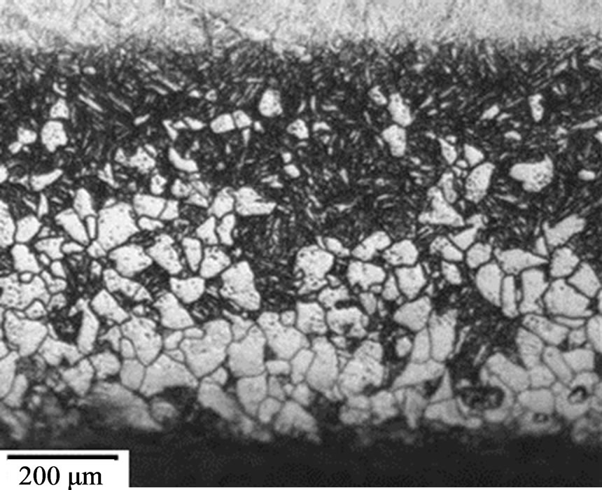 (b)
(b)
Figure 14. Micrographs of sample heat treated at 1020˚C in an uncontrolled atmosphere for 5 hours (a) as quenched state, (b) third nitrided state.
show the comparison between as quench state and nitrided state for samples heat treated without atmosphere control.
The micrographs show the gas nitriding process introduce the harden layer within the decarburized layer by letting nitrogen to diffuse into the core region and alter the surface composition [14]; however, the compound layer cannot be found on the surface. The results suggest the gas nitriding itself does not have any direct influence on the hardness profile of the inner part of the samples. It is because beyond the nitrided zone, the hardness profile closely matches the hardness profile of the respective second tempered condition. From this, it shows the advantage of using vacuum furnace over the muffle furnace. If the nitrided layer does not cover the decarburizing zone, there is a significant hardness drop below the nitrided layer, which may result in mechanical failure.
4. Conclusion
The effect of the heat treatment atmosphere on H13 tool steel hardness has been investigated in this paper. It was shown that proper stainless steel foil wrapping on the heat treating specimen can restrict decarburization process, resulting in a constant hardness profile similar to vacuum heat treatment. However the tempering characteristic between these two heat treatment methods are different. For the pack carburization heat treatment, it was noted that the samples suffered from decarburization at early stage of the heat treatment as the carbon monoxide level was not adequate for carburization process. Results from the gas nitrided samples showed that the thickness and the hardness of the nitrided layer are independent to the carbon content in H13 steel. After two rounds of the gas nitriding process, further nitriding seemed to have no significant effect on the hardness and the thickness of the nitrided layer.
REFERENCES
- M. L. Fares, M. Athmani, Y. Khelfaoui and A. Khettache, “An Investigation into the Effects of Conventional Heat Treatments on Mechanical Characteristics of New Hot Working Tool Steel,” IOP Conference Series: Materials Science and Engineering, Vol. 28, No. 1, 2012, Article ID: 012042.
- J. Zhang, Y. Zhong, S. Sun and J. Yin, “Heat Treatment of H13 Hot Working Die Steel for Die Casting,” Special Casting and Nonferrous Alloys, Vol. 29, No. 3, 2009, pp. 237-239.
- C. Zhang, R. Chen, F. Luo, C. Du and W. Shi, “Effect of Heat Treatment Process on Microstructure and Properties of H13 Steel,” Heat Treatment of Metals Vol. 37, No. 10, 2012, pp. 119-121.
- T. Björk, R. Westergård and S. Hogmark, “Wear of Surface Treated Dies for Aluminium Extrusion—A Case Study,” Wear, Vol. 249, No. 3-4, 2011, pp. 316-323. http://dx.doi.org/10.1016/S0043-1648(01)00550-6
- S. S. Akhtar, A. F. M. Arif and B. S. Yilbas, “Influence of Multiple Nitriding on the Case Hardening of H13 Tool Steel: Experimental and Numerical Investigation,” International Journal of Advanced Manufacturing Technology, Vol. 58, No. 1-4, 2012, pp. 57-70. http://dx.doi.org/10.1007/s00170-011-3387-2
- G.-Y. Lin, X.-Y. Zheng, D. Feng, W. Yang and S.-H. Zhang, “Effects of Heat Treatment on Nitrided Layer of H13 Tool Steel,” Iron and Steel (Peking), Vol. 43, No. 12, 2008, pp. 63-66.
- S. S. Akhtar, A. F. M. Arif and B. S. Yilbas, “Evaluation of Gas Nitriding Process with in-Process Variation of Nitriding Potential for AISI H13 Tool Steel,” International Journal of Advanced Manufacturing Technology, Vol. 47, No. 5-8, 2010, pp. 687-698. http://dx.doi.org/10.1007/s00170-009-2215-4
- L.-P. Wang and X.-C. Wu, “Influencing Factors of Performance for Austenitic Hot Die Work Steel,” Kang Iron and Steel (Peking), Vol. 43, No. 11, 2008, pp. 78-81.
- G. H. Yan, X. M. Huang, Y. Q. Wang, X. G. Qin, M. Yang, Z. M. Chu and K. Jin, “Effects of Heat Treatment on Mechanical Properties of H13 Steel,” Metal Science and Heat Treatment, Vol. 52, No. 7-8, 2010, pp. 393-395. http://dx.doi.org/10.1007/s11041-010-9288-4
- Y.-L. Chen, B. Liu and J.-Y. Li, “Study on Heat Treatment of Nitrogen H13 Steel,” Advanced Materials Research, Vol. 146-147, 2011, pp. 1885-1888. http://dx.doi.org/10.4028/www.scientific.net/AMR.146-147.1885
- M. L. Fares, M. Belaid, O. Chahaoui, H. Ghous and Y. Khelfaoui, “An Investigation on the Usefulness and Performance of New Hot Working Tool Steel by Nitrocarburizing Process,” e-Journal of Surface Science and Nanotechnology, Vol. 10, 2012, pp. 1-11. http://dx.doi.org/10.1380/ejssnt.2012.1
- A. Arain, “Heat Treatment and Toughness Behavior of Tool Steels (D2 and H13) for Cutting Blades,” M.Sc. Thesis, University of Toronto, Toronto, 1999.
- W. E. Bryson, “Heat Treatment, Selection, and Application of Tool Steels,” 2nd Edition, Hanser Publications, Cincinnati, 2005.
- J. Vatavuk, L. C. F. Canale, G. E. Totten and S. G. Cardoso, “The Effect of Nitriding on the Toughness and Bending Resistance of Tool Steels,” International Journal of Microstructure and Materials Properties, Vol. 3, No. 4-5, 2008, pp. 563-575. http://dx.doi.org/10.1504/IJMMP.2008.022036
NOTES
*Corresponding author.