Open Journal of Acoustics
Vol.04 No.04(2014), Article ID:52030,19 pages
10.4236/oja.2014.44019
Theory and Simulation Analysis of the Mode Shape and Normal Shape Actuators and Sensors
Jwo Ming Jou
Department of Mechanical Engineering, Cheng Shiu University, Kaohsiung City, Taiwan
Email: joujm@csu.edu.tw
Copyright © 2014 by author and Scientific Research Publishing Inc.
This work is licensed under the Creative Commons Attribution International License (CC BY).
http://creativecommons.org/licenses/by/4.0/


Received 16 October 2014; revised 5 November 2014; accepted 2 December 2014
ABSTRACT
In this paper, we will try to find a universal theoretical model and approximate solutions which can be applied to both mode shape and normal shape actuators and sensors, and which can be predicted the gain of the first three modes of the mode shape and normal shape actuators and sensors, finally through computer simulation analysis to validate. In order to prove the feasibility of the theory and as well as convenient to use on the electro-mechanical engineering, we will try to simplify the three-dimension structure problem into an one-dimension structure problem. Furthermore we will design one kind of bimorph type piezoelectric cantilever beam, so that it can be used as with the actuator and sensor simultaneously, but also conducive to the theory and simulation analysis. As for the simulation analysis, we will use the ANSYS code.
Keywords:
Mode Shape, Normal Shape, Actuator, Sensor, Gain, The First Three Modes, ANSYS Code

1. Introduction
Due to the piezoelectric materials (such as PZT or PVDF) have the advantages of fast response and high actuating force, so they are very suitable made for sensors and actuators to sense and control the vibration of the flexible structures, especially to sense or control the low frequency vibration, because the high-frequency vibration is very easy to be absorbed by the structure itself. So that the most piezoelectric sensors and actuators are used to sense and control the low frequency vibration of flexible structures. And since the design concept and theory of the modal sensors and actuators have been proposed by C.K., Lee [1] [2] , making them to sense and control the low frequency vibration of flexible structures are more rapid, sensitive, precise, accurate and efficient. In which the main design concepts and methods of the modal sensors and actuators are based on the coating of the effective electrode surface and changing of the polarization direction with specific modal or mode shape, shown as Figure 1. As for the theoretical model, it is entirely based on the mode shape functions or spatial distribution methods. It is successfully pulled out the transverse vibration displacement of the coupling multi-modal by the mode shape functions or spatial distribution methods. Next, it uses the coating methods or the functions of effective electrode surface to sense or control the low frequency vibration of the flexible structures. Since the relevant theoretical analysis, computer simulation and experimental eleven were uncovered or presented [3] - [9] . In addition, the theoretical model of modal or mode shape actuator is also applied to the different types of piezoelectric transformers, thereby to enhance their step-up ratio and conversion efficiency [10] [11] .
However, the theoretical model is only applicable to modal sensors and actuators, but it can’t be applied on the normal shape sensors and actuators. If the theoretical model of modal sensors and actuators used in the normal shape sensors and actuators, we could not find the correct approximate solution. That is, so far, we still can’t find one kind of universal equation to simultaneously describe or predict the behavioral of the mode shape and normal shape sensors and actuators, or to compare the gain or to distinguish the difference between the mode shape and normal shape sensors and actuators from past studies.
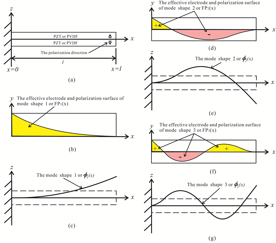
Figure 1. (a) The side view of the polarization direction of the bimorph piezoelectric cantilever beam; (b) The top view of the effective electrode surface of mode shape 1; (c) The side view of the mode shape 1; (d) The top view of the effective electrode surface of mode shape 2; (e) The side view of the mode shape 2; (f) The top view of the effective electrode surface of mode shape 3; (g) The side view of the mode shape 3.
In this paper, we will try from the original actuator and sensor equation, and electromechanical boundary conditions to find one kind of universal theoretical model and reasonable approximate solutions to compare the gain and difference between the mode shape and normal shape sensors and actuators. Furthermore we will also through the analysis results of computer simulation to verify the correctness and feasibility of the universal theoretical model and approximate solutions.
2. Actuator Equation
In order to understand the differences between the mode shape and normal shape actuators and sensors, we just start from the one-dimension actuator equation of bimorph type piezoelectric cantilever beam. The main contribution of this equation comes from the bending effect, so the membrane effect can be completely ignored. Therefore, the equation can be simplified to as follows [12] :
 . (1)
. (1)
where the moment M1 can be divided into two terms of the mechanical  and electrical moment
  as follow:
 . (2)
. (2)
As for the constants in the above Equations (1) and (2) can be defined as follow:
 . (3)
. (3)
 . (4)
. (4)
 . (5)
. (5)
wherein above the symbols of c11, D11, h, w, t, x, z and  are defined as the Young’s modulus, bending stiffness constant per unit width, thickness, transverse displacement, time, longitudinal coordinate, transverse coordinate and density.
Furthermore the electrical moment  of Equation (2) can be divided into two terms of time domain and space domain as follow:
 . (6)
. (6)
And
 . (7)
. (7)
wherein above the symbols of FPn, l,  are defined as the function of effective electrode surface of the nth mode shape, length, natural angular velocity (natural frequency), mode shape eigenvalues, mode shape constant and mode shape function.
Let Equations (2)-(7) substituted into Equation (1), and after finishing, we can get a non-homogeneous partial differential equation of motion with transverse displacement of mode shape actuator as follows:
 . (8)
. (8)
When the surface is uniformly coated and normal polarization with the bimorph type piezoelectric cantilever beam, that is, the function of effective electrode surface of Equation (7) can be redefined as:
 . (9)
. (9)
Then, the second derivative of electrical moment becomes zero.
 (10)
(10)
So for the normal shape actuator, Equation (8) can be simplified as:
 . (11)
In order for the mode shape and normal shape actuator equations can be applied to structures of different lengths, we can try to make Equation (8) and Equation (11) become the dimensionless equations:
 . (12)
And
 . (13)
where the dimensionless mode shape constant can be redefined as:
 . (14)
where the solution form of Equation (12) and Equation (13) can be expressed as:
 . (15)
And
 . (16)
Furthermore let the homogeneous solution of Equation (16) and Equation (17) are assumed to be as follows:
 . (17)
As for the particular solution of Equation (15) is assumed to be as follows:
 . (18)
where the symbols of  are defined as the undetermined coefficient and dimensionless homogeneous transverse displacement.
We can take Equation (17) into Equation (12) and Equation (13), then after finishing, we can get a dimensionless homogeneous four-order ordinary differential equation, as:
 . (19)
where the dimensionless natural eigenvalue of mode shape is defined as:
 . (20)
And the ith natural resonance frequency of piezoelectric beam multilayer or mode shape or normal shape actuator can be derived by Equation (20), as:
 . (21)
We can further get a dimensionless homogeneous solution from Equation (19)
 . (22)
In addition, we can take Equation (18) into Equation (12), so get the undetermined coefficient as:
 . (23)
where the relationship of the fourth-order differential function and zero-order function is:
 . (24)
So Equation (23) can be rewritten as:
 . (25)
Thus we can get the solution of the undetermined coefficient.
 . (26)
where  or
or  in normal or natural state.
At this point, we can find the general solution of mode shape and normal shape actuator, as:
 . (27)
And
 . (28)
Next, we can find the special solutions of the bimorph type piezoelectric cantilever beam from the electro- mechanical boundary conditions as follow:
 . (29)
And
 . (30)
Or
 . (31)
And
 . (32)
where the dimensionless mode shape function of mode shape actuator under clamped-free boundary conditions as:
 . (33)
And the dimensionless eigenvalues  and parameters
  of mode shape can be obtained from the following transcendental equation and formula:
 . (34)
And
 . (35)
According to the electro-mechanical and clamped-free boundary conditions, we can determine the constants of Equation (27) and Equation (28), as follow:
 . (36)
And
 . (37)
where the constants of mode shape actuator are defined as
 . (38)
And
 . (39)
where the second-order and third-order derivative mode shape function on the free boundary as follow:
 . (40)
And
 . (41)
As for the constants of normal shape actuator were defined as
 . (42)
And
 . (43)
which let  for the function of the effective electrode surface of normal shape actuator.
Until now, we can get a dimensionless general solution of the mode shape and normal shape actuator as follow:
 . (44)
And
 . (45)
Due to the high frequency vibrations can easily be absorbed by the structure itself, so we are only interested in low-frequency vibration. And in order to understand the difference between the mode shape and normal shape actuators, we analyzed only for the first three resonant modes of the structures. And according to Equation (34) and Equation (35), we can get the eigenvalues and parameters of the first three modes, shown as Table 1. As the same time, we can get the dimensionless mode shape functions of the first three resonant modes by Equation (33) and Table 1, shown as Figure 2. And we can also get the dimensionless function of the effective electrode surface of first three modes when let Equation (33) take into Equation (7), shown as Figure 3. In addition, we can

Figure 2. The dimensionless mode shape function of the first three modes of mode shape actuator relative to the unit length of structure when i = n.

Figure 3. The dimensionless function of the effective electrode surface of the first three modes of mode shape actuator relative to the unit length of structure when i = n.

Table 1. The eigenvalues and parameters of the first three modes of mode shape actuator under clamped-free boundary conditions.
get a dimensionless transverse displacement of the mode shape and normal shape piezoelectric stator under steady state and the same driving conditions as shown in Figure 2.
Another according to Equation (40) and Equation (41), we can get the second and third derivative of mode shape function of the first three modes of mode shape actuator relative to the unit length of structure, shown as Figure 4 & Figure 5. And we can further that  of the first three modes of mode shape actuator at free end. Therefore in, we can let Equation (44) further simplified as follows:
 . (46)
So far, Equation (46) of mode shape actuator appeared to be consistent with the particular solution of previously papers [1] [10] [11] .
Furthermore, we can make Equation (45) of normal shape actuator simplifies to
 . (47)
where the dimensionless mode shape function of normal shape actuator is defined as
 (48)
(48)
And the dimensionless parameters  of normal shape actuator is defined as
 (49)
(49)
According to Equation (46) and Equation (47), we can get the ratio of dimensionless transverse displacement

Figure 4. The second derivative of mode shape function of the first three modes of mode shape actuator relative to the unit length of structure when i = n.

Figure 5. The third derivative of mode shape function of the first three modes of mode shape actuator relative to the unit length of structure when i = n.
of mode shape and normal shape actuator under conditions of steady state, constant driving voltage and the same bending stiffness constant per unit width as follows:
 . (50)
In order to facilitate understanding of the difference between mode shape and normal shape actuator, we can
set the above ratio at the free end, that is,  , shown as Figure 2. There-
fore Equation (50) can again be expressed as
 . (51)
3. Sensor Equation
For the bimorph type piezoelectric cantilever beam under condition of constant electric potential, the sensor or current equation per unit length and width of the mode shape and normal shape sensor can be expressed as [12] :
 . (52)
And we can further take Equation (46) and Equation (47) into Equation (52) respectively, let Equation (52) be divided into two types of sensor or current equations as follow:
 . (53)
And
 . (54)
where the first derivative of dimensionless mode shape function of the first three modes can be obtained from clamped-free boundary conditions, or known from Figure 6. Therefore the ratio of dimensionless current of the mode shape and normal shape sensor dependent of eigenvalues under conditions of clamped-free, steady state, the same driving voltage and bending stiffness constant per unit width as follows:
 . (55)
where the first derivative of dimensionless mode shape function of the mode shape and normal shape sensor can

Figure 6. The first derivative of dimensionless mode shape function of the first three modes relative to the unit length of structure when i = n.
be expressed as follow:
 . (56)
And
 . (57)
Since the current is proportional to voltage under condition of the same load RL, So Equation (55) can also be expressed the ratio of dimensionless voltage of the mode shape and normal shape sensor as follows:
 . (58)
4. Case Study: Theory and Simulation Analysis
In order to understand the differences between mode shape and normal shape actuators and sensors by theory and simulation analysis, we specially design a series of one-dimension bimorph type piezoelectric cantilever beams, including the mode shape and normal shape actuators and sensors, shown as Figure 7. Wherein the size and physical properties of the one-dimension bimorph type piezoelectric cantilever beam can refer to Table 2. In addition, we will use the ANSYS code to simulate analysis the mode shape and normal shape actuators and sensors. Where we have chosen the element type is the scalar tetragonal 98 of couple field. Furthermore we will do the most sophisticated cutting of mesh, so that the analysis of the results can be quickly converged. As for the analysis types, we were selected the modal, static and steady state.
Wherein the step of theoretical analysis is as follows:
(1-1) Using different frequency spacing  to analyze the dimensionless transverse displacement and current or voltage of the first three modes of the mode shape and normal shape actuators and sensors from Equations (46) and (47) and Equations (52) and (53).
(1-2) Selecting the minimum frequency spacing  to analyze the ratio of the dimensionless transverse displacement and current or voltage and the mode shape function of the first three modes of the mode shape and normal shape actuators and sensors from Equation (50) and Equation (58).
As for the step of simulation analysis is as follows:
(2-1) Modeling of the mode shape and normal shape actuators and sensors respectively, including select element type, enter the physical properties, as well as coordinate system conversion, as shown Figure 8.
(2-2) Meshing of the mode shape and normal shape actuators and sensors respectively, including select the most sophisticated cutting of mesh or select the smart size 1, as shown Figure 9.
(2-3) Solving of the mode shape and normal shape actuators and sensors respectively, including setting boundary conditions of electro-mechanical, as shown Figure 10. All of which driving voltage on the effective electrode surface is 1.0 V.
(2-4) Post-processing of the mode shape and normal shape actuators and sensors respectively, includes processing the first three modes, the maximum deformation or electric potential, as shown Figures 11-13.

Figure 7. The schematic diagram of the mode shape and normal shape actuators and sensors.
Table 2. The size and physical properties of one-dimension bimorph type piezoelectric cantilever beam.
5. Results and Discussion
According to the results of theory analysis, we found:
1) Under condition of the frequency spacing of 100 Hz, the maximum dimensionless transverse displacement of the second modal of the normal shape and mode shape actuators is smaller than the first and the third modals’, as shown in Table 3 and Figure 14-(a-3). In addition, the maximum dimensionless voltage of the normal shape and mode shape sensors is proportional to the modal, as shown in Table 3 and Figure 14-(b-1).
2) Under condition of the frequency spacing of 10 Hz, the maximum dimensionless transverse displacement of the normal shape actuators is inversely proportional to the modal, as shown in Table 4 and Figure 14-(a-2). Furthermore, the maximum dimensionless transverse displacement of the second modal of the mode shape actuator is smaller than the first and the third modals’, as shown in Table 4 and Figure 14-(a-2). As for the normal shape and mode shape sensors, the maximum dimensionless voltage is proportional to the modal un-
 (a) (b)
 (c) (d)
Figure 8. Modeling and setting physical properties of the mode shape and normal shape actuators and sensors. (a) The normal shape actuator and sensor; (b) The mode shape 1 actuator and sensor; (c) The mode shape 2 actuator and sensor; (d) The mode shape 3 actuator and sensor.
Table 3. The maximum dimensionless transverse displacement and voltage of the first three modes of the mode shape and normal shape actuators and sensors under condition of the frequency spacing of 100 Hz.
Table 4. The maximum dimensionless transverse displacement and voltage of the first three modes of the mode shape and normal shape actuators and sensors under condition of the frequency spacing of 10 Hz.
 (a) (b)
 (c) (d)
Figure 9. Meshing the mode shape and normal shape actuators and sensors. (a) The normal shape actuator and sensor; (b) The mode shape 1 actuator and sensor; (c) The mode shape 2 actuator and sensor; (d) The mode shape 3 actuator and sensor.
der condition of the frequency spacing of 10 Hz, as shown in Table 4 and Figure 14-(b-2).
3) Under condition of the frequency spacing of 1 Hz, the maximum dimensionless transverse displacement of the second modal of the normal shape and mode shape actuators is larger than the first and the third modals’, as shown in Table 5 and Figure 14-(a-1). As for the maximum dimensionless voltage of the normal shape and mode shape is proportional to the modal under condition of the frequency spacing of 1 Hz, as shown in Table 5 and Figure 14-(b-1).
4) Overall, in addition to the modal 1 or the first modal and under condition of the frequency spacing of 100 Hz, the gain or ratio of the second and third modal of the mode shape actuators and sensors are better than normal shape actuators and sensors, as shown in Table 6.
5) In terms of the resonance frequency, the approximate solutions through theoretical derivation are consistent with the analysis results by computer simulations, as shown in Table 7.
6) Under conditions of the simulation analysis of static, steady state and modal types, the first modal of the normal shape and mode shape actuators and sensors are the same gain or ratio, as shown in Table 8, Table 9 and Figure 15.
7) Furthermore, the gain or ratio of the second and third modal of the mode shape actuators and sensors are better than the normal shape actuators and sensors, as shown in Table 8, Table 9 and Figure 15.
6. Conclusion
According to the results of the theory and simulation analysis, on the whole, we found the first modal of the
 (a) (b)
 (c) (d)
Figure 10. Solving Process_ Setting boundary conditions of electro-mechanical the mode shape and normal shape actuators and sensors. (a) The normal shape actuator and sensor; (b) The mode shape 1 actuator and sensor; (c) The mode shape 2 actuator and sensor; (d) The mode shape 3 actuator and sensor.
Table 5. The maximum dimensionless transverse displacement and voltage of the first three modes of the mode shape and normal shape actuators and sensors under condition of the minimum frequency spacing (Δfi = 1 Hz).
Table 6. The gain or ratio of dimensionless transverse displacement and voltage of the mode shape and normal shape actuators and sensors relative to the frequency under condition of different frequency spacing (Δfi = 1 Hz, 10 Hz & 100 Hz).
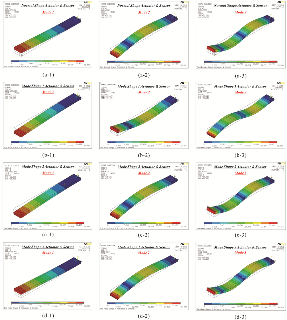
Figure 11. Post-processing the first three modes and the maximum deformation of the mode shape and normal shape actuators and sensors. (a) The first three modes of the normal shape actuator and sensor; (b) The first three modes of the mode shape 1 actuator and sensor; (c) The first three modes of the mode shape 2 actuator and sensor; (d) The first three modes of the mode shape 3 actuator and sensor (analysis type: modal).
normal shape and mode shape actuators and sensors are the same gain. Or in other words, the design concept of the first modal of mode shape actuator or sensor is not necessarily better than of the first modal of normal shape actuator or sensor, or even worse. However, the gain of the second and third modal of the mode shape actuators

Figure 12. Post-processing the first three modes and the maximum electric potential of the mode shape and normal shape actuators and sensors. (a) The first three modes of the normal shape actuator and sensor; (b) The first three modes of the mode shape 1 actuator and sensor; (c) The first three modes of the mode shape 2 actuator and sensor; (d) The first three modes of the mode shape 3 actuator and sensor (analysis type: modal).
and sensors are better than the normal shape actuators and sensors under any operating states. Most importantly, we have to find a universal theoretical model and approximate solutions in this paper, which can predict the gain of the first three modes of normal shape and mode shape actuators and sensors, and through the analysis results
 (a) (b)
 (c) (d)
Figure 13. Post-processing the electric potential output state of the mode shape and normal shape actuators and sensors. (a) The normal shape actuator and sensor; (b) The mode shape 1 actuator and sensor; (c) The mode shape 2 actuator and sensor; (d) The mode shape 3 actuator and sensor (analysis type: steady state).
Table 7. The resonance frequency and the ratio of resonance frequency of the first three modes of the mode shape and normal shape actuators and sensors by theory and simulation analysis (analysis type: modal).
Table 8. The maximum deformation and the ratio of maximum deformation of the mode shape and normal shape actuators by simulation analysis (analysis type: static & steady state).

Figure 14. (a-1)-(a-3) The dimensionless transverse displacement  of the mode shape and normal shape actuators relative to the frequency under condition of different frequency spacing; (b-1)-(b-3) The dimensionless current
  or voltage
  of the mode shape and normal shape sensors relative to the frequency under condition of different frequency spacing.
Table 9. The maximum sensing or output voltage and the ratio of maximum sensing or output voltage of the first three modes of the mode shape and normal shape sensors by simulation analysis (analysis type: modal).

Figure 15. (a-1)-(a-3) The maximum dimensionless transverse displacement  of the first three modes of the mode shape and normal shape actuators relative to the dimensionless length under condition of different frequency spacing; (b-1)-(b-3) The maximum dimensionless current
  or voltage
  of the first three modes of the mode shape and normal shape sensors relative to the dimensionless length under condition of different frequency spacing.
of computer simulation to confirm.
Acknowledgements
This study can be finished smoothly, I especially want to thank MOST of Taiwan of ROC sponsor on funding, (Project No.: MOST103-2221-E-230-007).
References
- Lee, C.-K. (1987) Piezoelectric Laminates for Torsional and Bending Modal Control: Theory and Experiment. Ph.D. Dissertation, Cornell University, Ithaca.
- Chiang, W.-W. and Lee, C.-K. (1989) Critical Active Damping Control of a Flexible Slender Plate Using a Distributed Modal Actuator and Sensor. American Control Conference, 700-706.
- Vaz, A.F. and Farr, T.J. (1997) Experimental Validation of Analytical Models of Flexible Structures with Bonded Piezoelectric Film Actuators and Sensors. IEEE Instrumentation and Measurement Technology Conference, 2, 887-892.
- Vat, A.F. (1998) Composite Modeling of Flexible Structures with Bonded Piezoelectric Film Actuators and Sensors. IEEE Transactions on Instrumentation and Measurement, 47, 513-520. http://dx.doi.org/10.1109/19.744200
- Takagi, K., Nagase, K., Oshima, K. and Hayakawa, Y. (2001) Modal Filtering for Simply Supported Plate Using Equally Segmented Piezoelectric Film. American Control Conference, 2, 1593-1598.
- Ballato, A. and Kim, Y.K. (2002) Displacements and Rotations of Practical Vibrational Modes of Piezoelectric Bimorph Cantilever Beams. Proceedings of IEEE Sensors, 2, 1294-1297.
- Gou, X.K. and Tian, H.M. (2007) Active Vibration Control of a Cantilever Beam Using Bonded Piezoelectric Sensors and Actuators. 8th International Conference on Electronic Measurement and Instruments, 4, 85-88.
- Rios-Gutierrez, M. and Silva-Navarro, G. (2009) Finite Element and Modal Modeling of a Cantilever Beam with Piezoelectric Patch Actuator for Vibration Absorption. 6th International Conference on Electrical Engineering Computing Science and Automatic Control, 1-6.
- Sanchez-Rojas, J.L., Hernando, J., Donoso, A., Bellido, J.C., Gutierrez, L.M., Ababneh, A., Seidel, H. and Schmid, U. (2009) Piezoelectric Modal Sensors/Actuators Based on Microplates Applying Surface Electrode Patterning. Solid-State Sensors, Actuators and Microsystems Conference, 2346-2349.
- Hsu, Y.-H., Lee, C.-K. and Hsiao, W.-H. (2005) Electrical and Mechanical Fully Coupled Theory and Experimental Verification of Rosen-Type Piezoelectric Transformers. IEEE Ultrasonics, Ferroelectrics and Frequency Control, 52, 1829-1839. http://dx.doi.org/10.1109/TUFFC.2005.1561639
- Huang, Y.-T., Wu, W.-J., Wang, Y.-C. and Lee, C.-K. (2007) Multilayer Modal Actuator-Based Piezoelectric Transformers. IEEE Ultrasonics Ferroelectrics and Frequency Control, 52, 359-367. http://dx.doi.org/10.1109/TUFFC.2007.249
- Jou, J.M. (2003) Piezoelectricity Mechanics. Chuan Hwa Book Co. Ltd., Taipei.