Open Journal of Acoustics
Vol.3 No.4(2013), Article ID:41093,7 pages DOI:10.4236/oja.2013.34018
Unidirectional Sound Signage for Speech Frequency Range Using Multiple-Loudspeaker Reproduction System
Graduate School of Science and Technology, Kumamoto University, Kumamoto, Japan
Email: vecky@hicc.cs.kumamoto-u.ac.jp, koshiro@hicc.cs.kumamoto-u.ac.jp, chisaki@cs.kumamoto-u.ac.jp, tuie@cs.kumamoto-u.ac.jp
Copyright © 2013 Vecky Canisius Poekoel et al. This is an open access article distributed under the Creative Commons Attribution License, which permits unrestricted use, distribution, and reproduction in any medium, provided the original work is properly cited.
Received November 7, 2013; revised December 7, 2013; accepted December 17, 2013
Keywords: Uni-directional; Reproduction System; Multiple-Loudspeaker System; Adaptive Filter; Propagation; Low Frequency
ABSTRACT
Human safety is the most important issue in disaster management. Speech is a sound signal containing information that is easily and quickly understood by humans. Using speech as sound signage in emergency systems can effectively increase human safety in low or poor visibility conditions such as in smoke-filled situations. However, reflections of sound through walls, floor surfaces, and ceilings will affect clarity of speech. Unfortunately, because of the characteristics of sound reproduction systems, a single loudspeaker propagates sound waves omni-directionally at low frequencies. This paper proposes a simple multiple-loudspeaker system for reproducing sound with uni-directional characteristics. The proposed system consists mainly of a primary loudspeaker for introducing sound in the desired beam, a secondary loudspeaker for reducing gain in the undesired direction, and digital filters. An adaptive finite-impulse-response (FIR) filter is used to produce the controlling sound by implementing a filtered-x least-mean-square algorithm, and a delay filter for adjusting the time alignment of sound propagation between primary and secondary sources at the control point. Several operational conditions for illustrating real situations and reflections were considered in an anechoic chamber. Experimental results show the directivity patterns of the proposed multiple-loudspeaker system for the required conditions. In a low frequency range, the system is able to control unidirectional propagation; there is a sound beam in the desired direction and, conversely, reduction of gain in the undesired direction around the control point.
1. Introduction
Emergency systems use alarms to sound emergency alerts and visual signs to show the direction of evacuation gates. The light emitted provides clear evacuation directions, but in smoke-filled situations, it may not be possible for people to see the emergency exit signs. In such situations, the alarm sound is effective in identifying the state of emergency, but it can not provide evacuation directions. One solution is an emergency system that has added directional sound. Directional sound has been designed by combining multiple tones and speech, which are separated by an appropriate time-delay. This sound is effective in guiding people to find emergency exits in tunnels [1]. In the tunnel or hallway, the sound field is highly reverberant because reflections of sound through walls and ceiling surfaces negatively affect the ease of hearing and understanding the content of speech. A time-delay technique has previously been proposed [2,3] that is used to delay the array of loudspeaker sounds alternately. Through this technique, directional sound can be produced and speech intelligibility in tunnels can be improved simultaneously. The speech from an array of loudspeakers that are alternately sounded can provide a clear picture of the direction, and thus the speech itself can be easily and quickly understood. Unfortunately, a single loudspeaker reproduces sound or speech omni-directionally in the low frequency range. Consequently, an undesired sound beam in the opposite direction to the primary loudspeaker may be produced which will disturb the development of unidirectional characteristics. Therefore, the effectiveness of a directional sound system may be further improved by applying multiple loudspeakers at multiple observation points.
A multiple-loudspeaker system has previously been developed to control the unidirectional radiation pattern. The system is composed of horn-type primary and secondary loudspeakers that configured face-to-face with the radiation pattern resembling a point source. Each loudspeaker is designed to radiate sound waves in the opposite direction. The system also has a unique sound reflector between the loudspeakers and a signal processor for controlling the secondary loudspeaker. The system is able to produce a unidirectional pattern effectively in a frequency range between 500 and 4000 Hz [4].
A unidirectional reproduction system that is focused on the low frequencies has previously been investigated [5]. The system consists of two loudspeakers that are configured back-to-back without a sound reflector between them, an adaptive digital filter (ADF) as a controller, and a microphone for adapting the ADF coefficients at adaptation stage. The primary loudspeaker faces to 0˚ in the desired sound direction, and the secondary loudspeaker is set to +180˚ for sound controlling. Experimental results show that the proposed system is effective in controlling unidirectional sound propagation by reducing undesired gain at low frequencies in the opposite beam direction. Another study developed unidirectional characteristics in the low frequency range for other configurations, that is, the secondary loudspeaker is set in the +130˚ direction [6]. The results show that the system is capable of sounding the beam in the 0˚ direction and reducing an undesired beam in the +130˚ direction at the target frequency. Multiple-loudspeaker systems have been verified in investigations into the effectiveness of the proposed unidirectional production systems [7,8].
We developed a unidirectional sound reproduction system for the low frequency range of speech with two ordinary loudspeakers configured back-to-back using several schemes with no sound reflector between the loudspeakers. In considering application of the system for hemisphere implementation, we also investigated its performance in terms of unidirectional propagation in situations where sound reflections occurred. The results of this study should benefit the development of emergency evacuation systems in hallways as a form of evacuation directional guidance.
2. Proposed Mulitple-Loudspeaker System
2.1. System Components
The proposed unidirectional sound reproduction system is shown in Figure 1. The main components of the system are a primary loudspeaker (LS-P) as the primary source, a secondary loudspeaker (LS-S) as the secondary source, a residual signal sensor (Mic-E), a delay filter L(z), an adaptive filter H(z), a model of the secondary path , electro-acoustic paths for primary and secondary sounds, and an On/Off switch for switching between modeling and control stages.
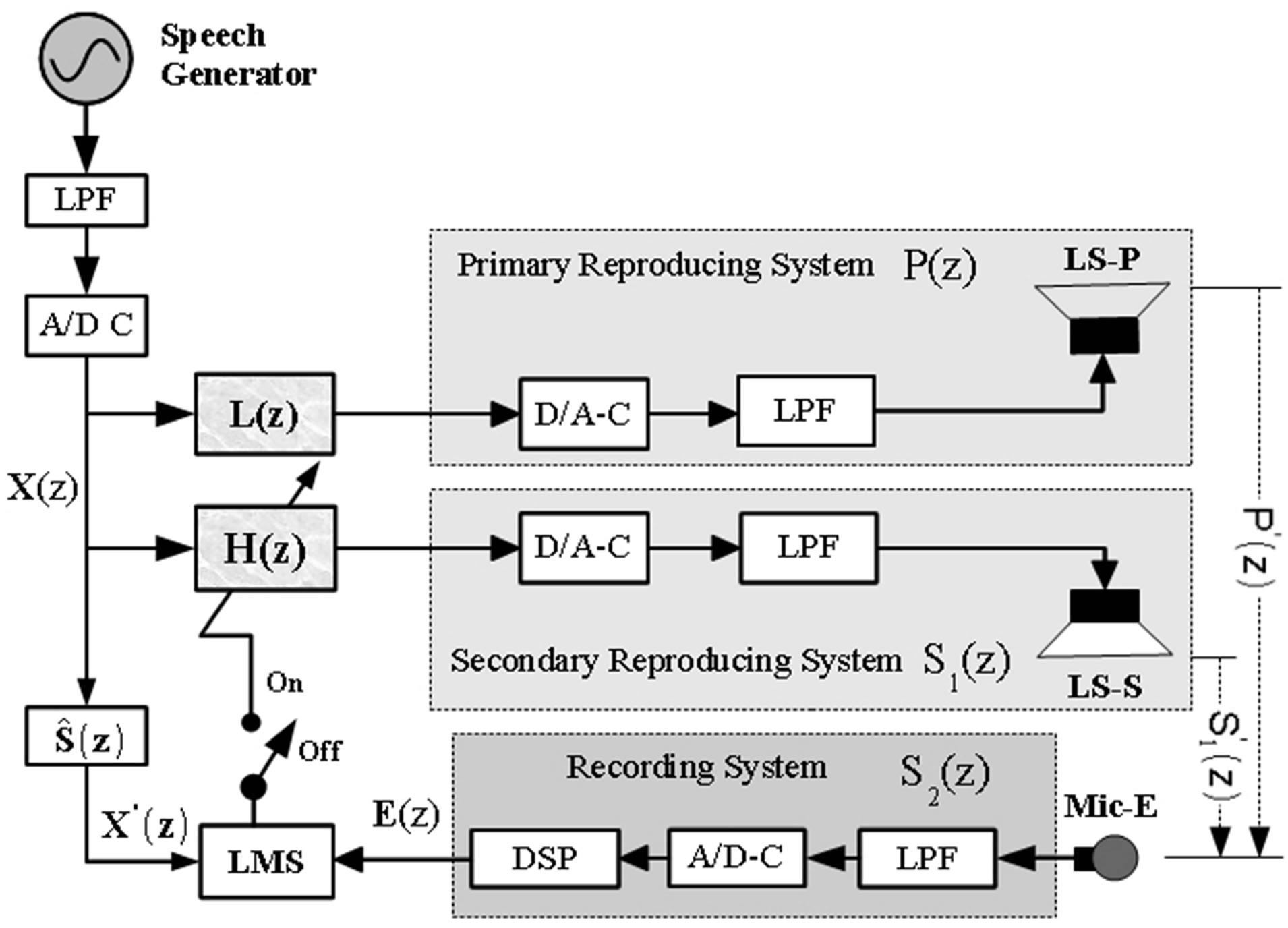
Figure 1. Proposed simple multiple-loudspeaker system for unidirectional reproduction system.
2.2. Electro-Acoustic Paths
The primary path is the electro-acoustic path from D(z) to E(z), which reproduces the desired sound in the LS-P direction as the desired beam direction. The other path is the secondary path, which is from Y(z) to E(z), for reproducing the control sound toward the secondary loudspeaker LS-S as the direction of the undesired sound beam. It is necessary to model both primary and secondary paths to obtain the characteristics. The characteristics of the primary path will be used to estimate the delay of the primary sound and to adjust the time alignment between primary and secondary propagation at the microphone side. Furthermore, the model obtained of the secondary path,  , is used to compensate for pure delay or causality constraint, for adapting the coefficients of the ADF, H(z), using a filtered-x least-mean square (FxLMS) algorithm at adaptation stage, because of the electroacoustic path
 , as in Equation (1).
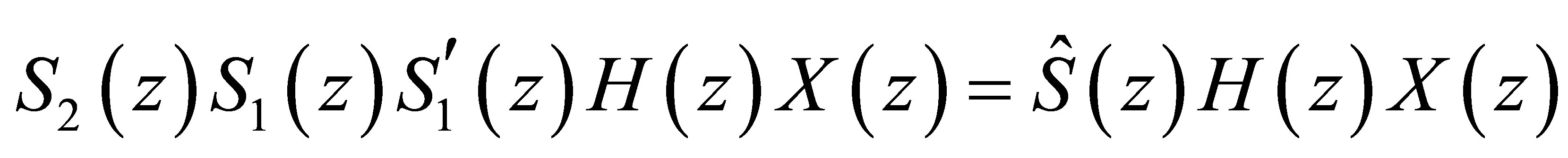 (1)
(1)
In order to estimate the impulse response of the secondary path, s(n), the output of the electro-acoustic path, y(n), is shown in Equation (2), where tsp(n) is the timestretched pulse, and m(n) is noise.
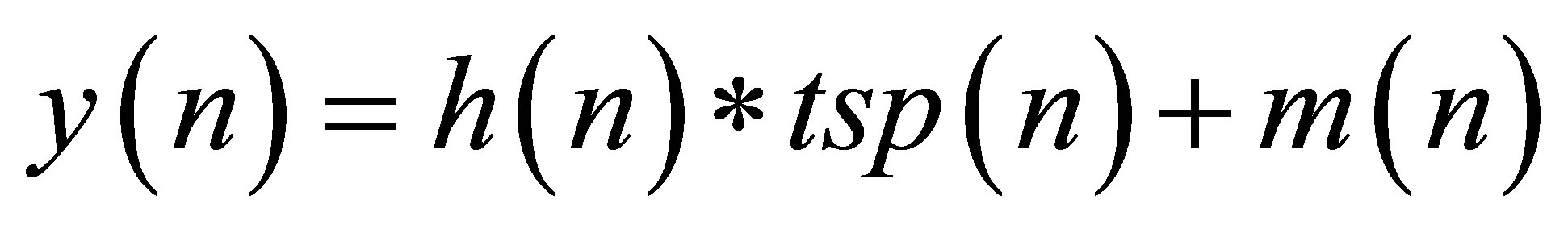 (2)
(2)
To observe the characteristics of both paths with a very long impulse response and wide dynamic range characteristics, we used optimized Aoshima’s time-stretched pulse (OATSP) [9]. With the OATSP method, we can generate a signal, tsp(n), and its inverse signal, intsp(n), simultaneously, which enables measurement of impulse responses longer than N (N = 2^i, I = integer), and its linear convolution between tsp(n) and intsp(n) is almost ideal with a flat power distribution in the frequency range. We averaged 1000 TSPs to obtain the electro-acoustic system output. Then the characteristics of the observed electroacoustic path were obtained after convolution between the obtained output signal, y(n), and the inverse of the OATSP signal, intsp(n), as in Equation (3), where (n-M) = tsp(n)*intsp(n) is the ideal impulse response, y(n) is the output obtained from 1000 TSPs, and m(n) is the noise that will reduce by increasing the signal-to-noise ratio, in this case by generating a 16-bit tsp(n) signal as the input.
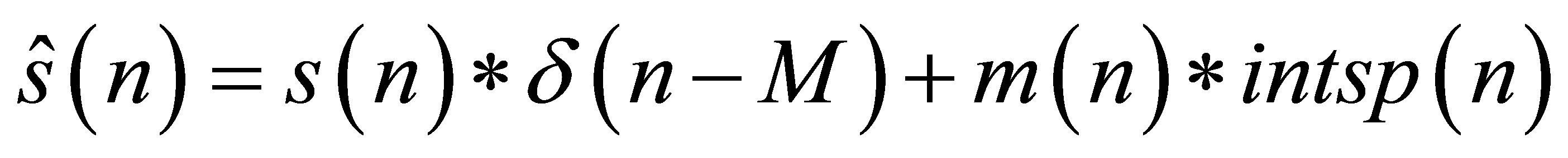 (3)
(3)
2.3. Performance of ADF Adaptation
The obtained secondary path model filters the input system, X(z). On the other side, Mic-E senses peaks in the residual sound pressure level as error signals as in Equation (4). Then the output of the secondary path model filter X'(z) together with the error signal E(z) are used to adapt the coefficients of the adaptive filter, H(z), by moving the switch (Figure 1) to the “On” position. The adaptation process adopts an active noise control (ANC) technique using the FxLMS algorithm.
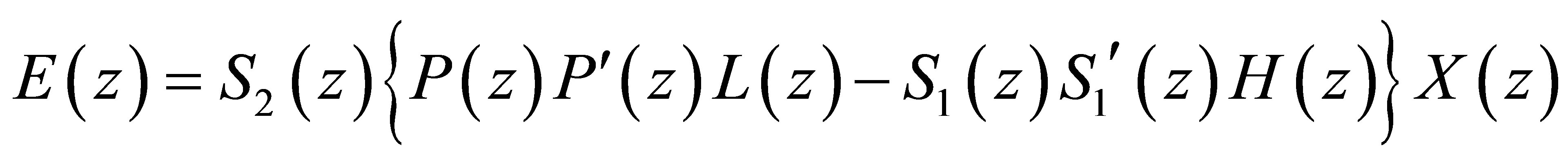 (4)
(4)
After the ADF has converged, the switch is moved to the “Off” position to obtain optimum ADF coefficients for controlling unidirectional propagation.
3. Directivity Control
The modeling and adaptation stages are preparation stages for calibrating acoustic environments or whenever there are characteristic changes. At the directivity control stage, the switch is in the “Off” position, and so configuration of the proposed system uses the delay filter, L(z), ADF, H(z) with fixed coefficients, analog interfacing, and primary and secondary loudspeakers. The direction of the primary loudspeaker is determined in order to highlight the desired sound or speech as the desired direction at 0˚ (P0). Then the direction of the secondary loudspeaker is adjusted in accordance with the direction of undesired sound gain, which will be reduced around the MicE position, such as around +230˚ (“S230” signifies that the sensor microphone is set to 230˚) for front-rear configuration. At this stage, white noise is generated to be introduced toward the primary source for the desired sound.
3.1. Directivity Pattern of Single Loudspeaker
Naturally, a single loudspeaker propagates sound waves omnidirectionally at a low frequency, and thus it will be unidirectional at higher frequencies as shown in Figure 2.
3.2. Multiple-Loudspeaker Reproduction System
We experimentally investigated, unidirectional propagation control using several loudspeaker configurations and variations in the parameters of FIR ADF, H(z), in accordance with its delay filter lengths L(z) in order to satisfy Equation (5).
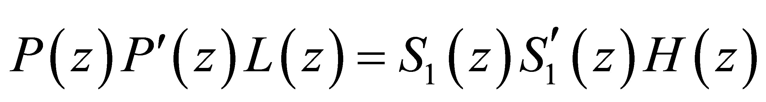 (5)
(5)
The primary loudspeaker was set to 0˚ as the desired beam, while the direction of the secondary was adjusted to the desired angle direction for gain reductions. Snapshots of the multiple-loudspeaker configurations are shown in Figure 3. Specifications of the equipment used to control unidirectional propagation are shown in Table 1, and parameter settings are shown in Table 2.
4. Results and Discussions
4.1. Directivity Control without Reflection
In observing the experimental results that are shown in Figures 4 and 5, it is clear that there were reductions of
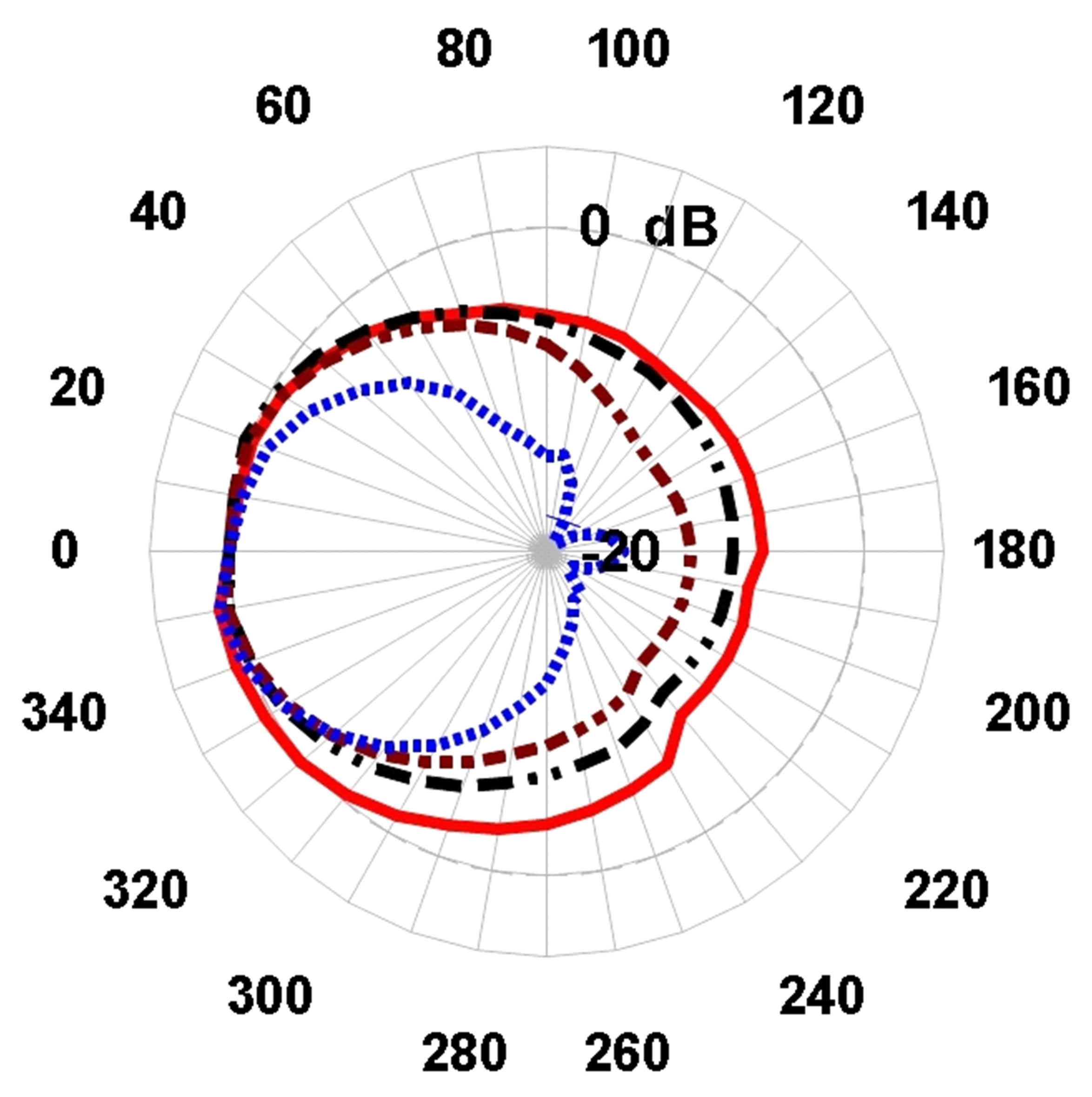
Figure 2. Propagation characteristics of a single loudspeaker, i.e., primary loudspeaker; red solid line denotes 100 Hz, black dash-dotted line denotes 300 Hz, brown dash-dotted line denotes 500 Hz, and blue dotted line denotes 1000 Hz.
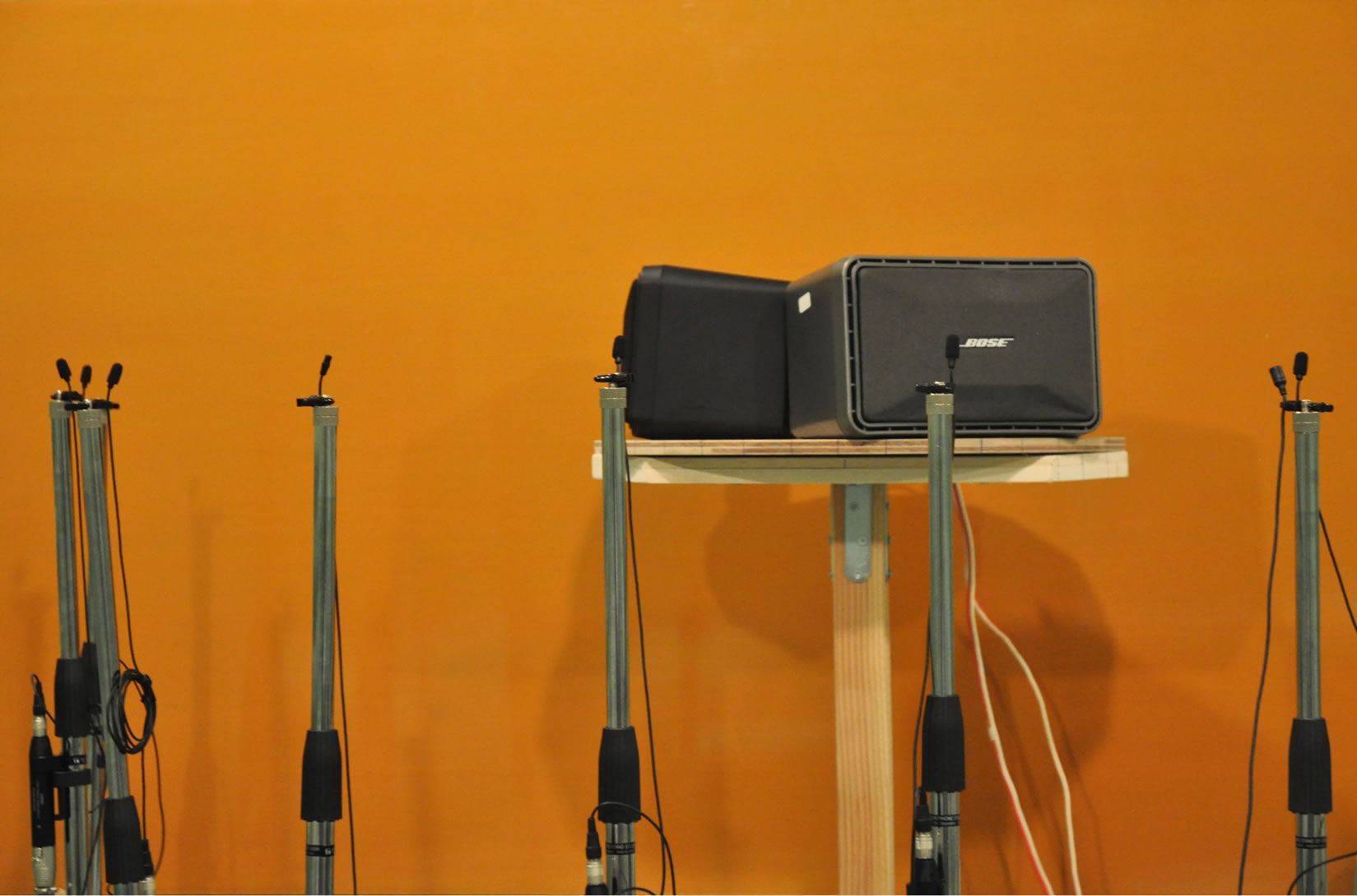
Figure 3. Loudspeaker configurations with reflection for uni-directional propagation control; back loudspeaker is the primary, 0˚ direction, and gray one is the secondary with adjusted angle direction.

Figure 4. Unidirectional pattern of multiple-loudspeaker system in the front-back configuration, or P0-S180, at 100 Hz, 300 Hz, and 600 Hz; red dashed line denotes performance without control and black solid line denotes performance under control.
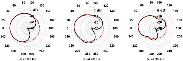
Figure 5. Unidirectional pattern of multiple-loudspeaker system in the front-rear configuration or P0-S230, at 200 Hz, 400 Hz, and 500 Hz; red dashed line denotes performance without control and black solid line denotes performance under control.
undesired gain in the direction of either S180 or S230 as the desired target, and on the other side there occurred a sound beam in the direction of P0 as the desired beam.
The direction of the secondary loudspeaker can be set as desired flexibly. In this case, the direction was S230 with the assumption that the loudspeakers would be placed on the ceiling, and so around the S230 direction was centered as the reduced coverage area.
Figure 4 shows the performance obtained using the P0- S180 configuration at frequencies of 100 Hz, 300 Hz, and 600 Hz.
There were undesired gain reductions centered at the +180˚ direction. By comparing the pattern of propagation between the reproduction system without and with control, there were gain reductions at 100 Hz for gain above 10 dB, from +110˚ to +250˚. However, there was a bump at +170˚ to +200˚ at a beam width of approximately 30˚. Here, at 300 Hz, reduction occurred for gain above 10 dB from +150˚ to +210˚, and above 7 dB from 160˚ to 200˚ at 600 Hz.
In order to investigate the ability and flexibility of control, experiments were performed using the P0-S230
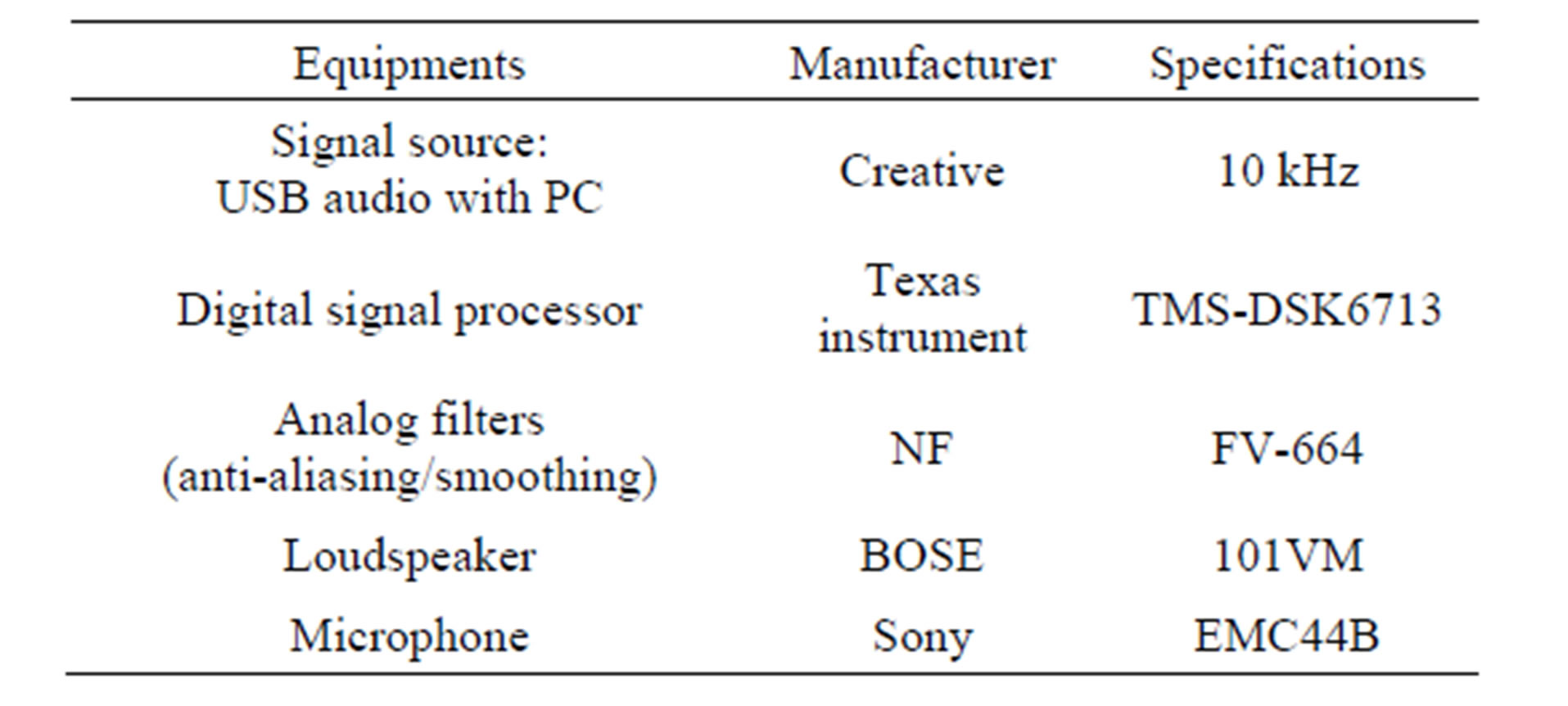
Table 1. List of equipment.

Table 2. Parameter settings.
configuration, and appropriate adaptive filter parameters corresponding to the delay system. Experimental results are shown in Figure 5, where the proposed system was still able to consistently control the unidirectional propagation as in previous tests. At 100 Hz, the reduction occurred for gain of above 5 dB, from +170˚ to +270˚ or at a beam width of approximately 100˚, without any bump. Further reduction occurred at 200 Hz above 10 dB from +180˚ to +250˚, and above 8 dB from +190˚ to +240˚ at 500 Hz.
4.2. Directivity Control with Reflection
For public address application, the proposed system consisting of a pair of loudspeakers can be placed on the ceiling or wall of a hallway, where the direction of the primary and secondary loudspeakers can be adjusted as desired. The direction of the primary loudspeaker is set as the desired sound beam, which is defined as the 0˚ direction, and the secondary loudspeaker can be directed in the desired direction flexibly for reducing undesired sound gain, to obtain characteristics of expected unidirectional propagation of the sound reproduction system.
In the following, we assume that the pair of loudspeakers is placed on the ceiling, which may reflect sound waves. In the reflection condition, experiments were carried out in an anechoic room by placing a sound reflecting surface on one side to represent the reflected ceiling. The distance between the sound reflector surface and pair of loudspeakers was approximately 45 cm. The primary loudspeaker was directed to highlight the desired sound, 0˚, and the secondary loudspeaker was set to +240˚, which is towards the bottom of the rear primary loudspeaker, to reduce low-frequency gain due to the omnidirectional propagation of the primary loudspeaker, shown in Figures 3 and 6. In the +240˚ direction, sound waves arrived directly from propagation of the primary loudspeaker and reflected by the ceiling surface.
On the signal processing side, the primary sound reproduction system was set to introduce the desired sound in the speech frequency range by using a low-pass filter set to cut-off frequency, fc = 3200 Hz. The other side, the secondary reproduction system for controlling the undesired sound gain at low frequencies, was set to fc = 1000 Hz, as the target. Measurements were made of the unidirectional propagation pattern using the microphone at intervals of +10˚ from +180˚ to +360˚ (0˚).
To investigate the directivity control performance of the proposed system in more detail in the reflection condition, Figure 7 shows the spectrum frequency of directivity control at +10˚ intervals from +180˚ to 0˚ (+360˚), and the unidirectional propagation obtained at interesting target frequencies with in the sound reflection condition in the hemisphere is shown in Figure 8.
The reflection affected directivity control for frequency components whose frequency was higher than 300 Hz, and interferences of waves had the same phase. There was gain control at approximately +240˚, which was the controlled target direction. There were gain reductions at approximately +240˚ at low frequencies up to 1000 Hz, and without control there was no reduction, i.e., at 2000 Hz and 3000 Hz.
Significant gain reductions with wide “lobes” were obtained at frequencies of 100 Hz and 200 Hz, which occurred at 100 Hz with an approximate 10 dB gain reduction from +180˚ to +310˚, and at 200 Hz with an approximate 17 dB from +190˚ up to +290˚. With other frequencies as controlled targets, there were not only reductions because of control but also gain at certain points due to the interference of waves. In these cases, there were attenuation and significant gain, where at 300 Hz, there
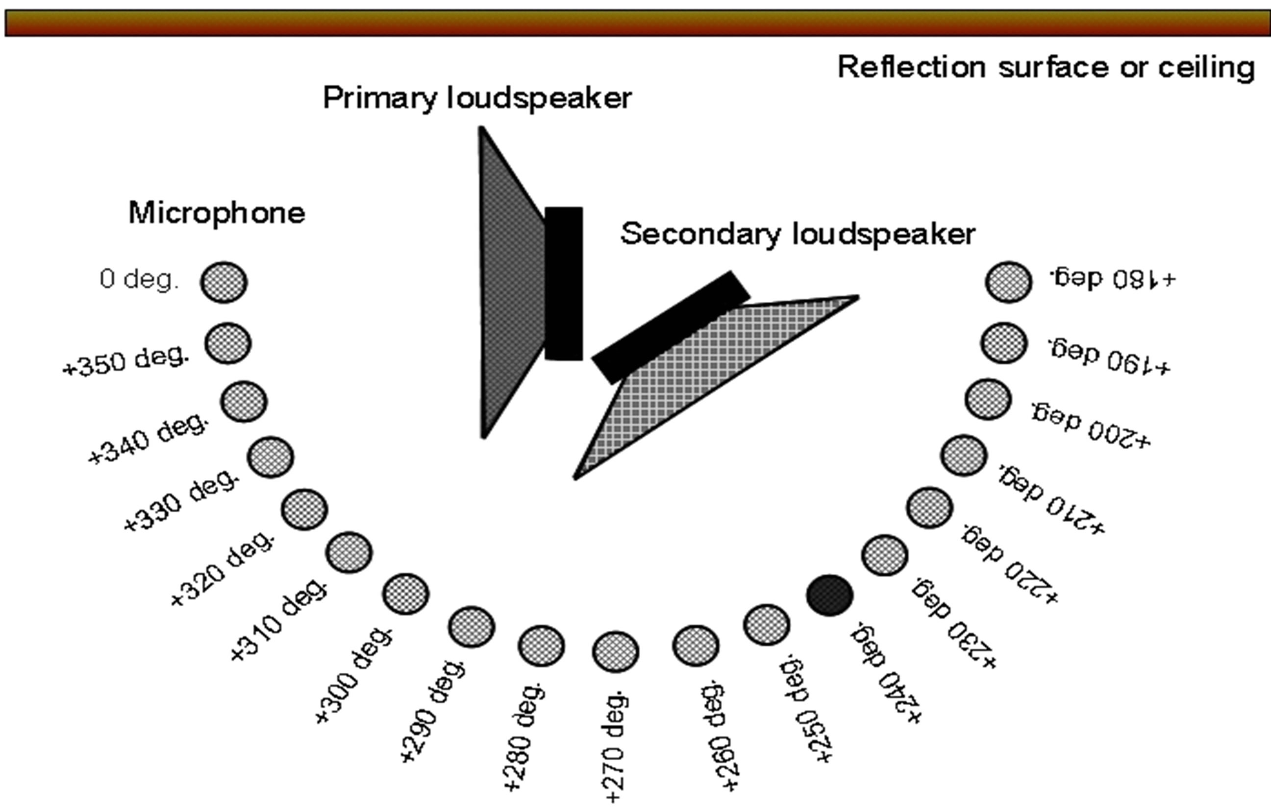
Figure 6. Configuration of unidirectional propagation measurement in hemisphere.
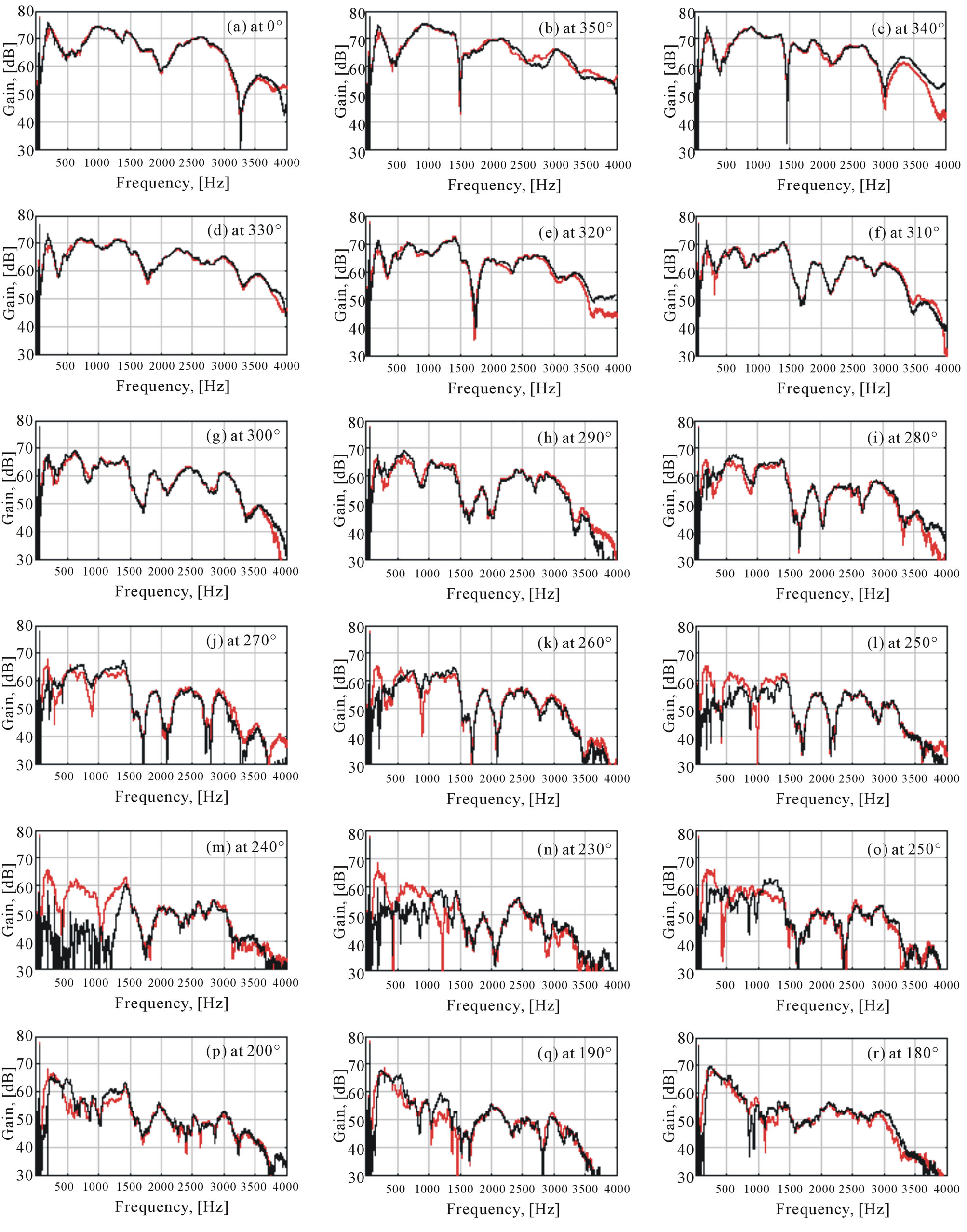
Figure 7. Response frequency of unidirectional control at +10˚ intervals from +180˚ to +360˚ (0˚) in hemisphere; black solid line denotes frequency response under control using the proposed system, and red solid line denotes frequency response without control.
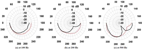
Figure 8. Unidirectional pattern of proposed multiple-loudspeaker system in the front-rear configuration, P0-S240 in hemisphere with sound reflection surface, at 100 Hz, 200 Hz, and 500 Hz; red dashed line denotes performance without control and black solid line denotes performance under control.
were reductions up to 23 dB at approximately +230˚ to +250˚ and approximately +210˚ to 230˚; there were gains up to 10 dB at +260˚ to +310˚; at 400 Hz, there were reductions up to 14 dB at approximately +230˚ to +250˚; at 500 Hz there were reductions up to 24 dB at approximately +230˚ to +270˚ and gain up to 13 dB at approximately +180˚ to +230˚; and finally at 600 Hz, there were reductions up to 28 dB at approximately +210˚ to +260˚.
5. Conclusions
A sound reproduction system to deal with a unidirectional propagation pattern in the low frequency range was proposed. The proposed system provides a unidirectional directivity pattern that works for target frequencies up to 600 Hz.
The proposed system is able to control the gain in the direction of the desired angle, +240˚, for each target in the low frequency range in a hemisphere.
Wider reductions occur at a frequency of 100 Hz and 200 Hz; there are reductions up to 10 dB with 150˚ width at 100 Hz, and up to 17 dB with 100˚. With other frequencies, magnitude reductions are larger, approximately 23 dB, 14 dB, 24 dB, and 23 dB, respectively, at 300 Hz, 400 Hz, 500 Hz, and 600 Hz, with 20˚ up to 50˚ beam width reductions.
The proposed system may be effectively implemented as a public address system for the development of an evacuation system.
REFERENCES
- L. C. Broer and S. J. Wijngaarden, “Directional Sound Evaluation from Smokefilled Tunnels,” Proceedings of First International Symposium Safe and Reliable Tunnels Innovative European Achievements, Prague, 2004, pp. 33- 41.
- S. Yokohama, H. Tachibana, S. Sakamoto and S. Tazawa, “Subjective Experiment on Speech-rate of Emergency Evacuation Announcement in a Tunnel,” Proceedings of Euronoise, 30 May - 1 June 2006, Tampere.
- S. Yokohama, S. Sakamoto, H. Tachibana and S. Tazawa, “Study on the Application of Time-delay Technique to Public Address System in a Tunnel,” Proceedings of Inter-noise, Rio de Janeiro Brazil, 2005.
- I. Kakuhari, H. Hashimoto and K. Terai, “Development of a Loudspeaker System with a Unidirectional Radiation Pattern in a Speech Frequency Range,” Journal of Acoustic Society of Japan, Vol. 21, No. 6, 2002, pp. 369-373.
- T. Usagawa, S. Murakami, V. C. Poekoel and Y. Chisaki, “On a Unidirectional Loudspeaker System for Low Frequency Range Reproduction Using ANC Technique,” Proceedings of Inter-Noise, Osaka, 4-7 September 2011, pp. 1-5.
- V. C. Poekoel, Y. Chisaki and T. Usagawa, “Uni-Directional Characteristics Developing in Low Frequencies Using Two Loudspeakers with Adaptive FIR Filter,” Proceedings of Youngnam ASK-Kyushu ASJ Joint Conference on Acoustics, 26 January 2013, pp. 66-69.
- V. C. Poekoel, Y. Chisaki and T. Usagawa, “Directivity Control of Loudspeaker System in Low Frequency Range,” Proceedings of the 7th International Conference on Information and Communication Technology, ICTS, Bali Indonesia, 15-16 May 2013, pp. 257-261.
- V. C. Poekoel, K. Hira, Y. Chisaki and T. Usagawa, “Effectiveness of Multiple Loudspeaker System for Developing a Low Frequency Uni-Directional Sound Reproduction System,” Proceedings of the 66th Joint Conference of Electrical and Electronics Engineers in Kyushu, JCEEE, Kumamoto, 25-26 September 2013.
- Y. Suzuki, F. Asano, H. Y. Kim and T. Sone, “An Optimum Computer-Generated Pulse Signal Suitable for the Measurement of Very Long Impulse Responses,” Journal of Acoustic Society of America, Vol. 97, No. 2, 1995, pp. 1119-1123. http://dx.doi.org/10.1121/1.412224