Open Journal of Acoustics
Vol.3 No.3(2013), Article ID:36742,8 pages DOI:10.4236/oja.2013.33012
A New Concept of Calculation Coefficietns of Reflection and Passage Sound Waves on the Boundary of Liquid Spaces
Institute of Applied Physics, Russian Academy of Sciences, Nizhny Novgorod, Russia
Email: ivg@hydro.appl.sci-nnov.ru
Copyright © 2013 V. P. Ivanov G. K. Ivanova. This is an open access article distributed under the Creative Commons Attribution License, which permits unrestricted use, distribution, and reproduction in any medium, provided the original work is properly cited.
Received July 14, 2013; revised August 16, 2013; accepted August 22, 2013
Keywords: Sound running waves; trajectory; phase; reflection; passage; liquid space; wave-guide
ABSTRACT
It is consider that, from the standpoint of the law of conservation of energy, the process of converting sound wave falls on the boundary between two spaces in two, leaving the boundary, reflected and passage. It is assumed that the simultaneous presence of three waves is impossible, and that the process of converting one wave in two waves occurs instantaneously. Based on this concept, enter the following boundary conditions for the calculation of amplitudes (coefficients) of the reflected and passage waves. The initial phases of the reflected and passage waves coincide with the phase of the falling wave. The energy of the falling wave is equal to the sum of the energies of the reflected and passage waves. The normal component velocity amplitude of the particle of the liquid under the influence of the falling wave is equal to the sum of the normal component of particle velocity amplitudes of the reflected and passage waves. It was found that the character of dependence of the reflection coefficient on the angle of departure of the initial wave is the same as in the traditional formulas, but the coefficient of passage does not exceed unity. Calculations of reflection and passage coefficients for different values of the refractive coefficient at the boundary between two homogeneous spaces as well as the canonical form of the waveguide, wherein the speed of sound which is minimum at predetermined depth is carried out.
1. Introduction
One of the problems is still causing a number of questions; it is the calculation of the coefficients of reflection and passage of sound waves at the boundary of two liquid homogeneous spaces with different densities and speeds of sound. The fundamental works on the determination of the coefficients of reflection and passage with ray method can be considered works [1-4]. However, received there coefficients of reflection (CR) and passing (CP) of the sound waves at the boundary cause a number of questions. Let us consider some of them.
It is seen, from formula for the CR, that under certain conditions it can be negative despite the fact that CR is actually the amplitude of the reflected sound wave, which the amplitude of any periodic function is always positive. To make a positive value CR some authors carried out the following mathematical operation—instead of the minus sign in front of the CR wave phase increase (or decrease) in the value of π, which makes the value of CR positive [1]. From this mathematical operation is concluded that when the sound wave reflects, there is occur jump of its phase at value π. But the jump in the phase sound waves to π in a fixed point in space (time) does ray acoustic not valid [2]. Note that the same situation exists in optics, the loss (or increase) in the phase of the electromagnetic wave to half the wavelength in the time of the reflection—a recognized result [5]. It is, in our view, an incorrect result, as will be shown below. Another discrepancy with the expected result is contained in the formula for the CP. In [1-4] CP can take values greater than the amplitude of the incident wave, which is contrary to the law of conservation of energy.
In [6,7], it’s indicated the widespread in literature error in the recording wave phase caused by the wave vector consideration as a scalar quantity, which leads, in particular, to an error in calculating the distance passed by the wave. In these works calculated CR and CP along the path of sound waves in a waveguide with varying speed of sound in depth. It is shown that in all trajectories points excluding the nearest to points of full internal reflections CR is close to zero and CP close to unity. On this basis, it was concluded that the path inversion occurs at the point where the angle of inclination equal to the angle of full internal reflection of the sound wave and not at a point where the path is horizontal, as is taken customary in ray acoustic. Changing the angle of turn trajectory leads to a slight change in it—of shortening the length as a result of reducing the angular range to the exclusion of the horizontal path. Corrections in the recording phase and calculating the trajectory of a sound wave, proposed in [6,7], do not remove shortcomings in the formulas for CR and CP.
In this paper, it is suggested a method of calculation of CR and CP, significantly different from the use of [1-4, 6,7]. The basic idea of the method is that there is either the falling wave or the reflected or passage waves. The simultaneous presence of all three waves contrary to the law of conservation of energy and it is therefore impossible. It is assumed that the transfer of energy of the falling wave to waves of the newly established instantaneously. As in [1-4], the first basic condition for the calculation of CR and CP is the equality of phases of all three waves at the boundary. New condition—equal the energy of the falling wave to sum energies reflected and passed waves. The third condition is the equality of the normal component of the velocity amplitude of motion of particles of the falling wave, the sum of the normal components of the particle velocity amplitude of the reflected and passed waves. This condition is also used in [1-4,6,7]. A brief account of the method of obtaining CR and CP is given in [8].
The fundamental equations of the propagation of sound waves in a compressible fluid are contained in the monograph [2]. These equations are obtained for the oscillation motion of a fluid under the action of an acoustic wave under the assumption that the changes the pressure p and density ρ is much smaller than their equilibrium values. Fluid velocity v, caused by a sound wave, is a small value too as the changes in pressure and density. The average velocity of the fluid is assumed to be zero. It is also assumed that small changes in pressure p and density ρ are related by p = c2ρ, where c—speed of sound in the liquid. This link of changes in pressure p and density ρ is used to exclude from the equations of motion one of the functions—changes in the density ρ. As a result, the equations for determining the functions p and v, describing the propagation of sound waves in the fluid is obtained. After these changes in the equations of motion come in two macroscopic quantities—the average value of the density, which will henceforth be denoted by ρ0, and the speed of sound c. With the help of the equations of motion it is easy to show that the pressure p and the modulus of the particle velocity v are related by: p = ρ0cv. This means that the pressure and particle velocity fluid proportional to each other and changing synchronously. In this paper, formulas for CR and CP are obtained using only the oscillation function of velocity of fluid v.
2. Running Sound Wave
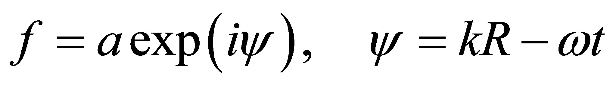
In ocean acoustics, propagation of sound waves is often described by the running wave satisfying the equations of fluid motion. Running sound wave is a function of spatial coordinates and time t:
 (1)
(1)
Running-wave phase ψ has two components—the spatial part of the scalar product (SP) of the vectors kR, and the time—ωt. The vector R is a path along which the energy of sound waves carried by the running wave. Vector k, the wave vector coincides with the direction of the tangent to the trajectory R, ω—angular frequency of the radiation source, t—time of spreading. By definition, a running wave vectors k, R are parallel at any point of the path, so their scalar product is the multiplication of their absolute values (lengths), kR = kR and does not depend on the choice of coordinate system [9,10]. A sound wave creates movement the particles of liquid (there compression and rarefaction) in the direction of propagation, and therefore it is a longitudinal wave. With the function (1) can be described as a sound wave field in the liquid, sources radiating, and the pressure and particle velocity fluid caused by a sound wave. You need to know only the trajectory of the wave and its wave vector. Wave features of the sound wave in that representation is absent. This way of defining the wave process is called the geometric approximation. Its use in place of the wave representation is possible only under the condition that the wave amplitude and direction do not change much over distances of the order of the wavelength [2]. We assume that the absorption of sound in the fluid is absent; the amplitude of the wave does not change, and change the speed of sound in depth such that over the wavelength results in minimal changes in vector k, and its magnitude and direction of propagation, invasive on its periodic nature. Under these conditions, the Expression (1) describes the acoustic field radiated by the source in the direction of the trajectory R in any of its wave characteristics.
Consider the basic properties of the phase ψ of a running wave. Both parts of phase (spatial and time) of the running wave change during its propagation, wherein the difference between them remains constant, equal to the initial phase or zero. Function (1) can be considered as a function of the coordinates (trajectory R) at a fixed time t or as a function of time at a fixed point in space. The amplitude of the “a” function f—is positive and constant determined by the radiation power source and its direction diagram. If the medium is not homogeneous, for including changes vector k along the path should be the calculation of the wave phase sequentially at each point of the trajectory. When the direction of the trajectory R changes, the direction of the wave vector k also changes following a change in direction of the vector R according to the definition of the running wave. In the literature, often considered only one change of direction vector R, and the vector k is regarded as a scalar. First of all this error in the calculation of the wave phase disturb the definition of the running wave and in a number of situations leads to the wrong physical conclusions [6,7].
Direction of propagation of the wave as such is not present in the phase of the wave, but effects on the calculation of the trajectory. If the function (1) describes the rate of fluid particles, the amplitude of the function (1) —vector, which coincides with the direction of the vector R. The velocity vector indicates the direction along which the wave propagates. The oscillating velocity of the fluid is a periodic function and change over time in each point of the trajectory with the frequency ω. At a fixed time, the fluid velocity is a periodic function of R along distance with the wavelength λ = 2π/k. Each part of the phase of the wave, the spatial and temporal increases as the wave propagates and is a carrier of information on distance (passed time). No other changes in the wave phase ψ, is not caused by the change of modules k, R, to the function (1) is not included. However, this property of the wave phase is often violated.
It is well known that CR acoustic wave, in some cases, according to existing formulas [1-4,6,7] becomes negative. It is considered that this should not be, because CR is a part of the energy passed on from the incident wave to the reflected wave can not be negative. Therefore, the negative sign is seen as a phase jump at the boundary by the amount of π due to a change in the direction of normal to the boundary component of the vector R in the opposite direction [1]. In our opinion, the phase jump upon reflection can not be. As noted above, the phase of the wave does not depend on the direction vectors k, R, but only on the path length of the vectors R and k. But the module vector k does not change upon reflection, because the reflected wave is in the same space as the incident. In the derivation of formulas for CR and CP is assumed that the coordinates of the point of reflection and refraction in the formula should not go. For its elimination initial phases of the reflected and refracted waves are equal phase of the incident wave. Age of the incident wave at the interface clearly not equal to zero and does not change. Artificial change of the phase of the reflected wave has the value of π to the point of reflection and breaks the continuity of the periodic structure of the sound field in the transition from the incident wave to the reflected and transmitted, that is, produces the same effect as a negative sign of the CR.
Similarly, unjustified change in the phase of the light reflection wave is made in optics. As in acoustics, it is believed that the reflection of the light wave leads to a jump on the wave phase π. It is known that the electromagnetic (EM) wave is represented by three vectors perpendicular to one another, k, E and H. They are oriented so that they form a group of right-handed or left-handed, depending on initial conditions. In optics, pay attention only to change the direction of the normal component of the electric vector E in the reflection, but do not take into account that the direction of the normal component of the wave vector k is reversed. Thus, the reflection of electromagnetic waves changes the direction of two of the three vectors describing the wave, but their relationship is not changed, they still make the right (or left) the top three. From the above explanation, it follows that in acoustics and optics, the introduction of the phase jump in the reflection caused by the lack of understanding of the process of reflection, namely, when the direction of propagation of the wave changes at the same time simultaneously change the direction of the vector k and vector R, but does not change their scalar product kR, ie phase of the wave.
3. Formulas for the Coefficients of Reflection and Passage of the Sound Wave
We assume that the plane of incidence is the plane (x, z). Since the vectors k, R parallel, their projections on the axes kx, Rx, kz, Rz are also parallel, i.e. have the same sign. Have the same signs and projections of the products kxRx > 0, kzRz > 0. Figure 1 shows the location of the sound rays near the boundary. Let the liquid medium is composed of two homogeneous half-spaces. Their boundary is parallel to the x-axis lies at a depth zb, density and sound velocity ρ, c and ρ1, c1 above and below the boundary. The sound source is located in the space with the parameters ρ, c. Incident on the boundary wave is described by vectors k, R; and the angle θ, measured from the axis z, k’, R’, θ’ and k1, R1, θ1—describes the reflected wave and the passed. Obviously, the desired expression for the CR and CP should be applicable at any point (xb, zb) at the interface. To eliminate the phase of the waves at the reflection point from the boundary conditions, it is as-
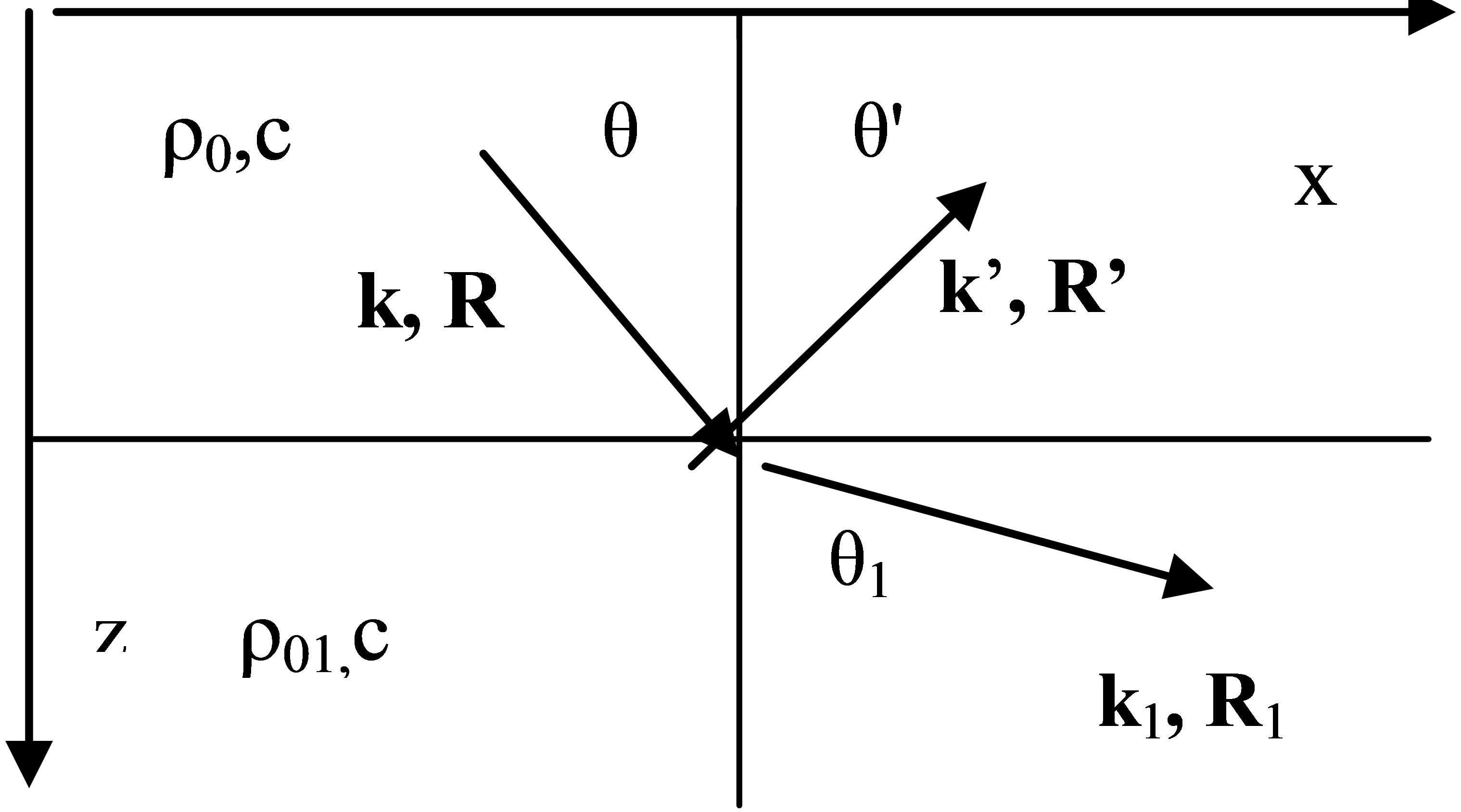
Figure 1. Sound rays at the boundary of spaces.
sumed that the initial phase of the emerging waves are phase of the incident wave at any point x at any depth z = zb. The equality condition of phases of three waves does not only eliminates the phase of the waves at the reflection point from the boundary conditions, but also preserve the continuity of the transfer of the oscillating process of energy of the incident wave to reflected and transmitted waves. We denote the incident wave that came to the boundary to a point (xb, zb), with mark i, the reflected and transmitted waves mark r and t. Time component of phases are omitted. As follows from Figure 1, signs projection vectors k, R along the axis x, z of the incident and transmitted waves are positive, signs zcomponents of the vectors k’, R’ of the reflected wave are negative.
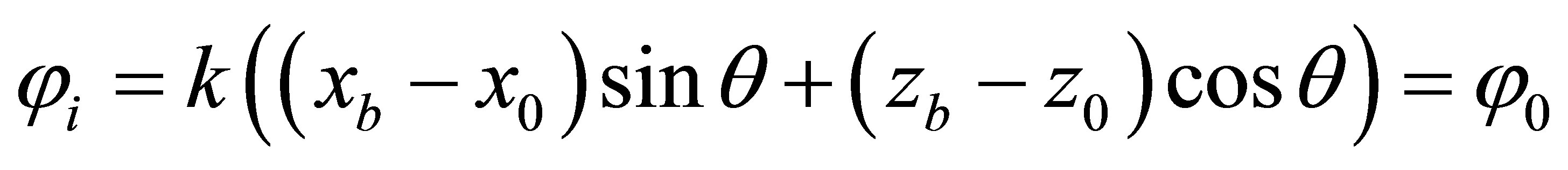
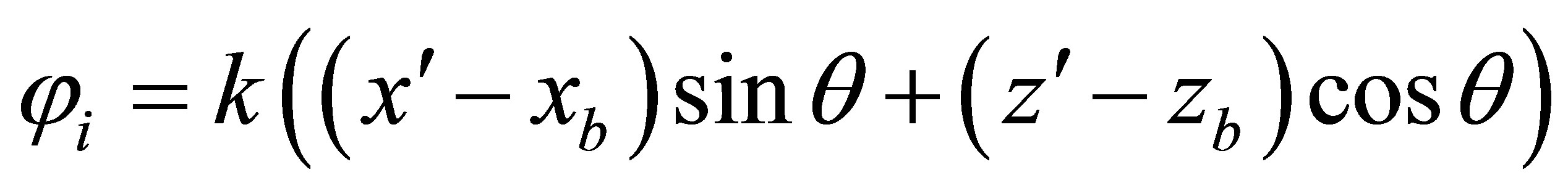
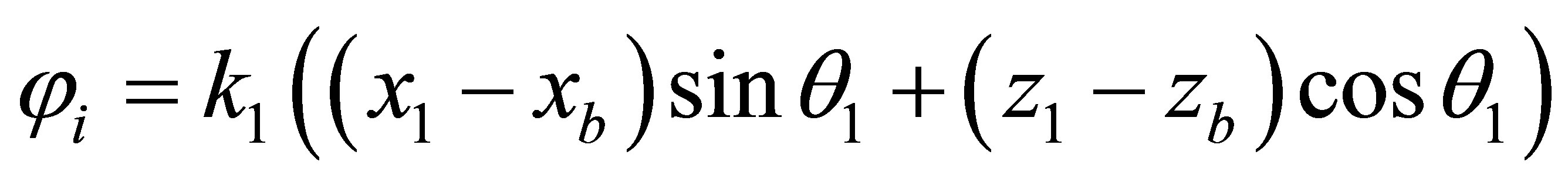
We write the spatial part of the phases of the three waves as shown in Figure 1. Phase of the incident wave φi is determined by the coordinates of the sound source (x0, z0) and a point on the boundary (xb, zb). The phases of the reflected and transmitted waves φr, φt are the initial coordinates (xb, zb), and the current coordinates (x’, z’) and (x1, z1), respectively. The angles of reflection and passage at the boundary, according to the laws of reflection, |θ’| = θ, sinθ1 = sinθ/n, n = c/c1—refractive index, k1 = ω/c1. Recording SP through the module does not contain the vector angles of propagation relative to the selected coordinate system. Therefore, to obtain the dependence of CR and CP from the angles of wave propagation traditionally is used a combined method of recording kR [9,10]. It contains propagation angles and coordinates trajectories.
 (2)
(2)
 .
.
The projections of the vector k in (2) are expressed in terms of its modulus k and the angle θ, kx = ksinθ, kz = kcosθ. The vector R in (2) is a projection on the coordinate axes, Rxi = (xb – x0), Rzi = (zb – z0), similarly recorded and Rr, Rt. In most works in recording phases, initial coordinates of the trajectories are not specified. In the combined method of record SP the sign of projections, Rx, Rz is contain in the differences between the final and initial coordinates of R. Signs of projections of the vector k are included in the sinθ and cosθ. In the vast number of works, for example, in [1-4], in the phase of the reflected wave a sign of Rz’ state separately, Rz’ = −z, (to be written −|z|), and the sign (−) cosθ projection kz’ = −k|cosθ| unknown. As a result, z-component of the SP in the reflected wave is negative and decreases rather than increases the SP in the propagation of the wave. This mistake in the recording phase of the passing wave was first pointed out in [6,7] and explained its implications. At a point on the boundary (xb, zb) x’= x1 = xb, z’ = z1 = zb. After their substitution in (2), phases of the waves are:
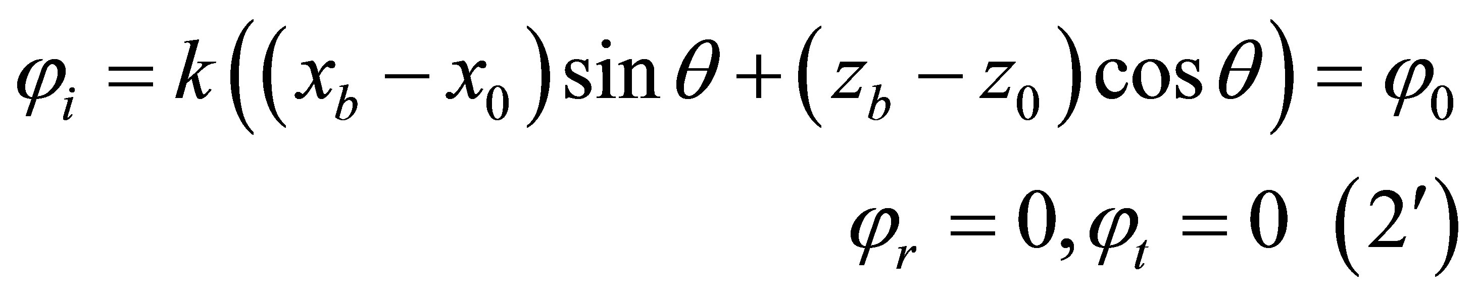
To eliminate the phase of the incident wave out of the boundary conditions in [1-4] is assumed that the boundary is at a depth of z = zb = 0. As can be seen from (2’), the phase of the incident wave is not excluded, since xb, x0, z0 are not equal to zero, and the sound source is not on the boundary at the point xb. To eliminate the phase of the incident wave is enough to accept that φr = φt = φ0. This is the first condition for calculation CR and CP.
We express the energy of sound waves through the particle velocity, E = ρv2, [2]. The law of conservation of energy at the interface after the elimination phases is:
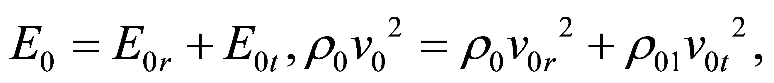 (3)
(3)
where E0, E0r, E0t—modules energies of the incident, reflected and transmitted waves, v0, v0r, v0t—vectors of velocity amplitudes of the fluid particles. We introduce coefficients that allow to comparison the three waves as for energy as well for the amplitudes of velocities: E0r/E0 = V2, E0t/E0 = W2. Here, V2 and W2—coefficients that represent the fraction of energy of the incident wave in the reflected wave and transmitted. Dividing in (3), the first equality in the E0 and use the notation for the ratio of the energies we get the law of conservation of energy at the boundary of spaces:
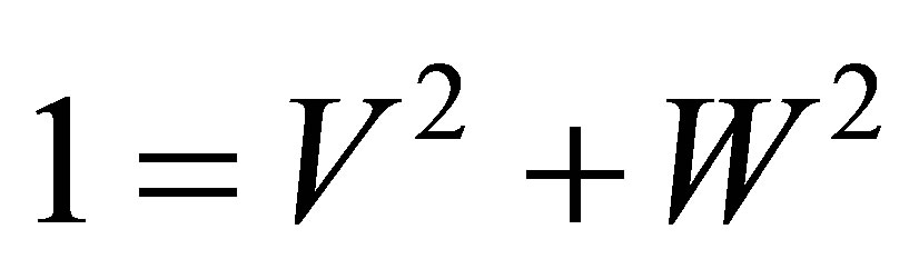 (3’)
(3’)
This is the second condition for the determination of CR and CP. The third condition is the same as that which is used in [1-4] and expressed by z-component of velocity amplitudes on both sides of the boundary spaces:
 (4)
(4)
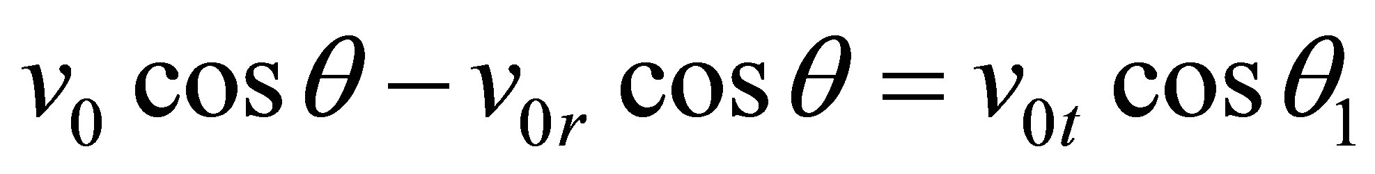
In (4), it includes modules of the amplitudes of the velocity vectors, the direction of z-component of the velocity vectors is expressed a sign in front of each term in (4) as shown in Figure 1. We express the amplitude of the particle velocity in each wave through her energy and divide them on the velocity amplitude of the incident wave:

From (4’), it follows that the coefficients of V and W, can be regarded as modules vectors of amplitudes velocity of the reflected and transmitted waves divided by the v0, the module of amplitude of the incident wave. According to Figure 1 negative sign has only a projection of the reflecting wave, vzr = −v0r cosθ. The sign (−), according to Figure 1, there is because cosθ’= −cosθ. Consideration of factors V and W as modules of vectors v0r, v0t is consistent with the expression of the wave energy across amplitudes of the velocity of the fluid particles, (3). Dividing (4) on the modulus of the amplitude of the incident wave, we obtain the relation of the relative amplitudes of z-component of velocity of three waves:
 (5)
(5)
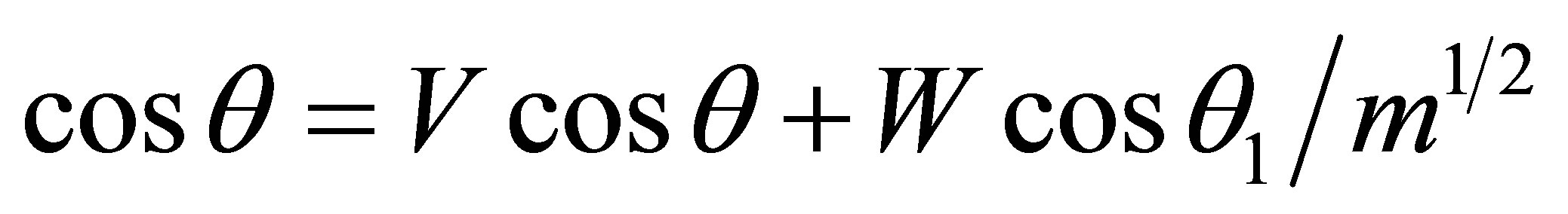
From Equations (3) and (5) we obtain the dependence of CR and CP from the angles of incidence and refraction:
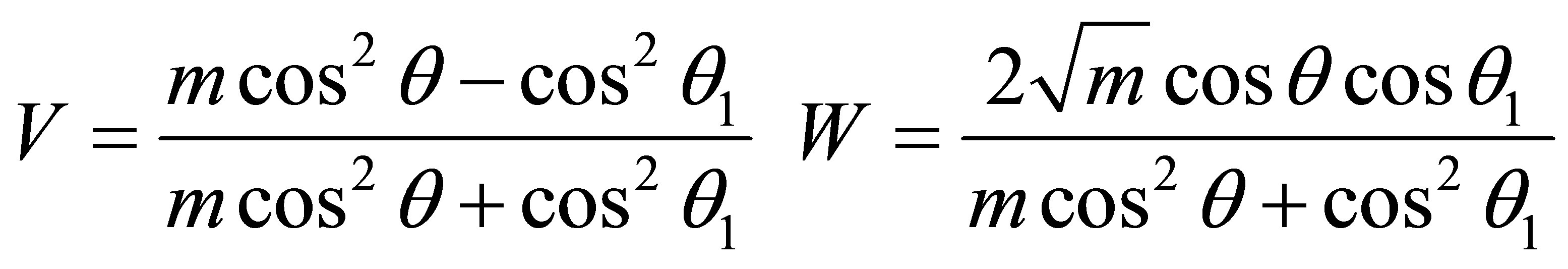 (6)
(6)
Refraction angle θ1 with the law Snelius expressed through the angle θ of the incident wave and the refractive index n: cos2θ1 = (n2 – sin2θ)/n2. To compare the two methods of calculation give similar formulas for CR and CP in [1]:
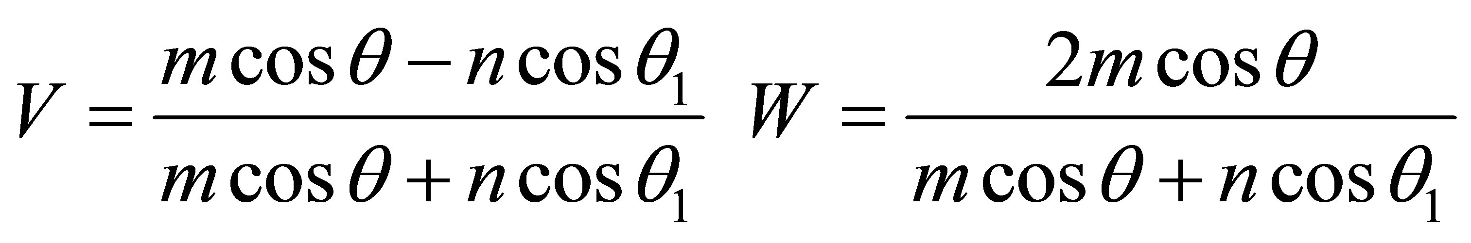 (7)
(7)
It can be seen that the structure of Formulas (6) and (7) is the same. The main difference in the CR (6) and (7) is that in (6), the refractive index n is included only in cosθ1, and passage coefficient W in (6) in the numerator is present as a factor cosine refraction θ1. Once again we note that the procedure for obtaining CR and CP, equations (3) and (5), show that V and W are positive values (modules).
4. Calculation of CR and CP for the Refractive Index n is Less than Unity
When the falling angle of sound wave at the boundary θ = 0, the passage angle θ1 = 0, too. For n < 1 and m > 1 from Formulas (6) and (7), the values V, W, V1, W1 are follows:
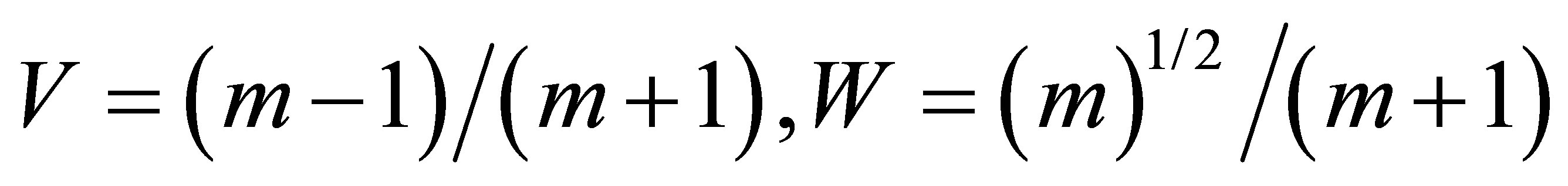 (6’)
(6’)
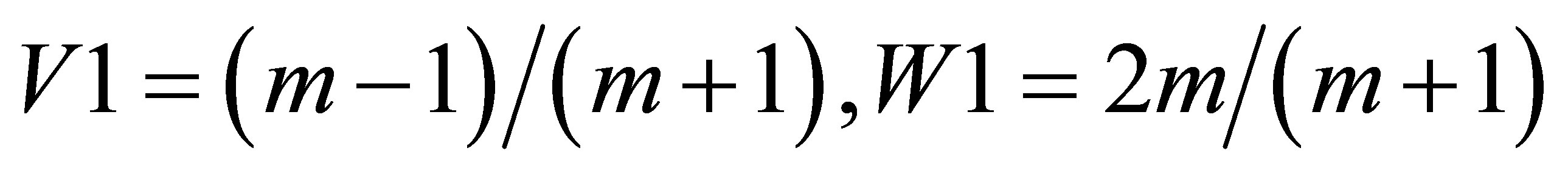 (7’)
(7’)
It is seen that reflection is a little; the wave goes at space with the bigger speed of sound without reflection practically. Coefficients V, V1 are the positive values.
From the law of refraction (Snelius) sinθ/c = sinθ1/c1, where θ, θ1—the angles of the falling and passed waves, follows the existence of an interesting phenomenon—the socalled full internal reflection (FIR) of the sound wave from boundary of spaces. At the boundary when n < 1 and when sinθ = n = c/c1, there is sinθ1 = 1. This means that cosθ1 = 0, vzt = v0t, cosθ1 = 0, the sound wave does not passage the boundary, and, according to (6), V = 1, W = 0. There is a full reflection of sound wave from the boundary. That the sound wave do not penetrate the boundary, it is clear from energy considerations, V = 1. Along (parallel to) the boundary the wave does not spread, sinθ = n < 1, the angle θ is less than π/2. The wave reflected from the boundary at an angle, called critical, θcr, sinθcr = n < 1. FIR angle is present in (7), but the amplitude of the passage wave is not vanish, W = 2, whereas according to the law of conservation of energy, it should be zero.
Will compare the CR and CP calculated by formulas (6) and (7), when the refractive index at the boundary n = c/c1 < 1, and the average density ratio m = 1. The values of the refractive index n chosen so that the falling angles took values θ = 50, 60, 70 and 80 degrees. Figure 2 shows the V and W, calculated as functions of angle θ from formulas (6), for n = 0.766, curve 1, 0.866—curve 2, 0.940—curve 3, 0.985—curve 4. As mentioned above at low angles of exit CR V close to zero, and CP W are close to the maximum possible value of 1. At the points of FIR, when V = 1, the values of W vanish, the falling wave is totally reflected out of the boundary at the critical angle, without penetrating into the second space. On figure 3 presents the calculation of CR and CP by formulas (7) for the same values of the refractive index n, as calculated in Figure 2. It can be seen that the CR has the same character as in Figure 2, but at the points FIR where V equal to 1, W increases from 1 to 2. This is the main difference between V and W, calculated according to the Formulas (6) and (7). Equation (6) for the CP gives the values corresponding to the law of conservation of energy, the growth of CR V accompanied by a reduction CP W.
Note that the points FIR of rays play a major role in the propagation of a sound wave in a wave-guide having the minimum of speed of sound at a certain depth. In [6,7], it is showed that the existence of points FIR in wave-guides leads to a change in the propagation direction of the trajectory at a certain depth in reverse. The result is the formation of a periodic structure of sound field along the horizontal, of repeated cycles, the length of which depends on the angle of the output trajectories of the source.
In the literature, which is a derivation of formulas for CR and CP, as in acoustics and in optics, great attention
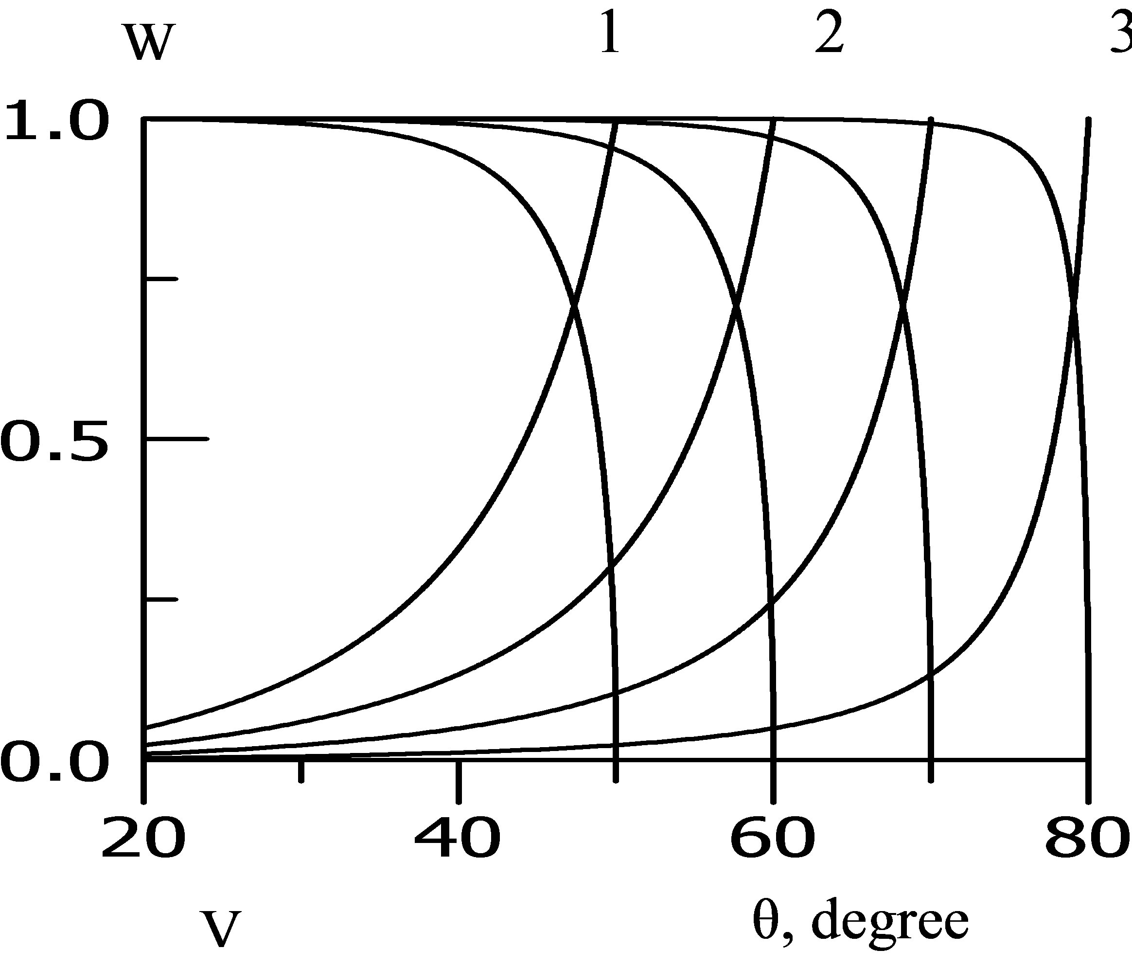
Figure 2. Coefficients V, W, account on (6).
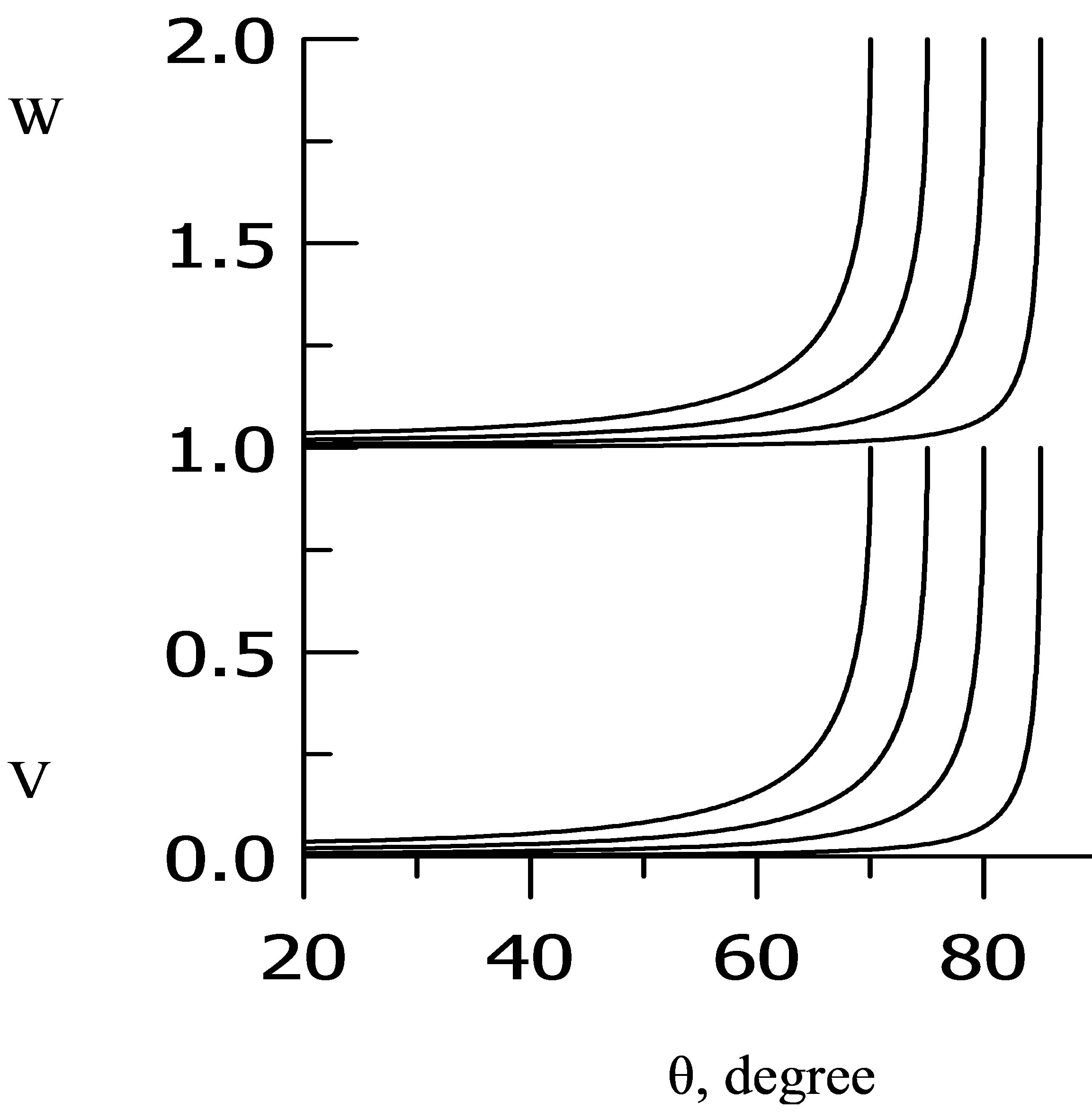
Figure 3. Coefficients V, W, account on (7).
is paid to the exit angles greater than the angle of departure: θcr <θ < π/2 when sinθ > sinθcr = n, but less than 1. According to the Law Snelius in this range of angles sinθ1 greater than one (which is impossible), and cosθ1 is the square root of a negative value. Therefore cosθ1 is consider as an imaginary quantity, cosθ1 = i (sin2θ – n2)1/2 /n. In this module, CR V = 1 and the phase appears CR., emerged, according to the authors of the review, at the boundary of the reflection waves [1,5]. In [6,7], they have done a review of the situation, based on the assumption that there is a small transition region between two spaces with sound speeds c and c1 where sound speed grows from the value c to c1 continuously. In this region trajectories with angles of departure θcr < θ < π/2 have FIR each at his own depth. They all have the real and positive value CRV.
All monographs with the introduction of the complex presentation of physical quantities cautions that the replacement of real functions is possible only when operations with complex functions is linear. Only in this case the transition to the real functions will be without errors. In present case, it is not so. Therefore the introduction of the complex presentation for CR is against the rules for a comprehensive presentation of physical function and is not applicable in this situation.
5. Calculation of CR and CP for the Refractive Index N is Greater than One
Upon receipt of the formulas for the CR and CP are no restrictions on the value of the refractive index between the two spaces was not introduced. Consider the propagation of sound waves from the space at a higher speed of sound in the space at a lower speed when n = c1/c2 > 1 and m < 1. From Snelius law it is easy to show that for n> 1 for any angle of exit CR V—negative. Indeed, when cos2θ1 = (n2 – sin2θ)/n2 and m < 1, the difference (mcos2θ – cos2θ1) = –(1 – m + sin2θ (1/m – 1/n2)) is negative value. Figure 4 shows the calculation of V and W for two values of n, 1.025 and 1.305, and m = 1. Calculation through Formulas (6) presents the lines thickened, through (7) thin lines. More gentle curves in Figure 4 are the greater value of n. As expected, CR V—negative throughout the all angular range. It is clearly seen that the difference in the account by the Formulas (6) and (7) for n > 1, is small. From Figure 4 is seen that the sound wave in a fairly long stretch the exit angles, ranging from zero (the fall of the boundary close to normal) easily penetrates into the space with the lower speed of sound, W ~ 1, the reflection from the boundary is small in absolute value, but has a negative sign. In this case from Snelius law is followed that a critical angle of exit at which the falling ray enters through the boundary has a lower sound velocity is angle sinθcr = n, sinθ1 = 1. Hence sinθ1 = 1/n—the highest possible value of the angle of passage θ1. But when θ = θcr = π/2 the sound wave in the medium with the lower speed of sound does not pass, because in (6) cos(π/2) = 0 and W = 0. The range of falling angles θ, at which the rays penetrate into the space at a lower speed of sound is between 0 and 1/n. Above mentioned that, by definition, the relations (3), (4’), V, W—proportional to the modulus of the amplitude of the reflected and transmitted waves and therefore must be positive values. That this is so follows from the calculation of the curves shown in Figure 4. For each curve for each corner the sum V2 + W2 = 1. This indicates that the magnitude |V| corresponds exactly to the energy conservation law (3’). The observed negative values of V may be due to not quite correct to use one function of the amplitude and the square of the amplitude (energy) of the sound wave. Negative values may be due to CR solutions of the quadratic equation for V, W. From the statement of the problem must be positive values V2 and W2, a sign of the square root of V2, W2, you can choose the one which corresponds to the physical values of V and W. If we accept this argument, in this case, you can not attach the sign (–) value and, where necessary, replace it with a plus.
In [1], the values of CR and CP when the liquid is bordered on air. It was noted above that the equations for the propagation of sound obtained under the assumption that the characteristics of the space ρ0 and p0—constants. Small changes in these quantities due to sound waves are allowed, but not by several orders on the boundary of

Figure 4. Coefficients V, W, thicken lines account by (6), thin lines—by (7).
liquid and air. The equations of motion of the fluid obtained in [2] for the propagation of sound, at the water - air obviously does not apply. If we assume that their application is possible, then the CR at the water-air V = −1. Negative values of CR V addresses in [1] as really existing, and are used, for example, in the construction of the wave theory of sound field in a waveguide.
6. Reflection and Passage Coefficients in the Propagation of Sound in a Canonical Wave-Guide
It is known that the speed of sound depends on the depth of the ocean, and in some cases may have minimum at a certain depth. Generally, when calculating the path an acoustic wave is consider the reflection of the sound energy is small and can be ignored. Obviously, this assumption is not possible when the inversion of the rays in the wave-guide incident with the angle of full internal reflection and is not with the area of horizontal spread of the ray. However, the depth of the point of turning trajectory defined by law Snelius. In [6-8], the calculation of CR and CP in a wave-guide of canonical type is done. There was selected the steepest trajectory at that waveguide along which as a function of distance from the source were calculated CR and CP. The wave-guide broke in depth on a number of horizontal layers between which V and W were determined by a successive transition from one layer to another. Width of each layer at a depth of δz = 0.25 m. Depth of the wave-guide axis z0 = 1 km, where the speed of sound is minimal and where the source of the sound was, the depth of the wave-guide zh = 4 km. Consider the behavior of CR and CP along the sloping path, in which the point of inversion of rays at the surface and at the bottom lies at a depth of 0.995 km and 1.005 km. The exit angle of the trajectory of the source θ = 89.9568140, turning angle at the surface θs = 89.9774346, at the bottom of θb = 89.9865258. Figure 5 (upper) shows the trajectory with the indicating the calculated points. Clearly visible point of FIR, they will show the break in the trajectory, not a smooth one, as in other parts of them. Figure 5 (below) shows a CR V, thickened curve, and CP W, slim curve. CP W along substantially the entire path except near the FIR points, close to 1. Extremes of V and W coincide with the points of FIR. Close by the waveguide axis in a small area at a depth the sound velocity is constant, n ~ 1, V and W are close to zero. Trajectory in this area does not change inclination, angle along the trajectory close to its angle of exit from thesource, the trajectory is close to a straight line as in a homogeneous medium. Negative values the CR V, as can be seen from Figure 5, is located in the areas after undergoing turning points in which the trajectory reaches the maximum depth for their angle of departure and turns to the region where the sound velocity

Figure 5. Upper—trajectory with the calculated points, lower—thin line V, thicken line W.
decreases.
7. Conclusions
On the basis of the law of conservation of energy formulas for the reflection and transmission coefficients of sound waves are obtained at the boundary of uniform spaces other than the traditional ones.
It was found that the nature of the reflection coefficient depends on the sound speed of the space in which the source is situate, more or less the speed of sound, and the formula for the coefficients for both cases are the same. If the sound source is located in a space at the lesser speed of sound, the transmission coefficient is close to unity and reflections—to zero but always positive. When the angle of the output trajectory is equal to the angle of full internal reflection, the sound is totally reflected from the boundary, without penetrating into the space at a higher speed of sound. If the sound source is located in a apace with a higher sound velocity, the reflectance throughout the range of angles output is negative, and the passage close to unity. Only for rays at grazing incidence to the boundary, the penetration into a space with lower sound velocity does not occur, and the square of the coefficient of reflectivity is equal to unity, the entire acoustic energy is in communication with the transmitter.
The calculations reflection and transmission coefficients showed that for the calculation of sound paths is sufficient to consider the reflection coefficient in the inversion points of full internal reflection, and in other points the reflection coefficient assumed to be zero, and the passage—one.
The existence of points of full internal reflection in a wave-guide with a minimum speed of sound is the cause of the frequency of sound paths existence of cycles, the length of which depends on the angle of departure from the source.
It is shown that the proposed in a number of studies in acoustics and optics compensation the negative sign of the reflection coefficient with change the phase of sound field (electromagnetic waves) on the value π contradicts the boundary conditions under which the formulas for the reflection and transmission coefficients were obtained.
The method of calculating the reflection and transmission coefficients based on the law of conservation of energy applies to optics. The coefficients of reflection and transmission of electromagnetic wave, whose electric field vector lies in the incidence plane, coincide with the same formulas for the sound wave.
The proposed method of obtaining the coefficients of reflection and transmission of sound waves the boundary of spaces based on the law of conservation of energy is not a perfect and final. Its main drawback, in our view, is that the reflection coefficients in finding the source of sound in the medium with greater speed of sound are negative.
REFERENCES
- L.M. Brehovskikh, “Ocean Acoustics,” Science, Мoscou, 1974.
- L.D. Landau and V. M. Lifshits, Hydrodynamics, М: the Science, 1988.
- L. M. Brehovskikh and O. A. Godin, “Acoustics of NonUniform Environments,” Т.1, М: the Science, 2007.
- L. M. Brehovskikh and A. A .Goncharov, “Introduction in Mechanics of Continuous Environments,” М: the Science, 1982.
- M. Born and E. Wolf, “Principles of Optics,” Moscow, 1973.
- V. P. Ivanov and G. K. Ivanova, “One Aspect of Sound Waves Propagation in Inhomogeneous Water Space,” Proceedings of the XXV-th Conference of the Russian Acoustic Society, Т.2, Moscow, 2012, pp. 338-341.
- V.P. Ivanov and G.K. Ivanova. “Some Aspects of Ray Representation Running Sound Waves in Liquid Spaces,” http://www.scirp.org/journal/oja,2013,3,7-13
- V. P. Ivanov and G. K. Ivanova, “A New Concept of Calculation of Reflection and Passage Sound Waves on the boundary of liquid Spaces,” Ocean Acoustics, Proceedings of the XIV-th L.M. Brekhovskikh’s Conference with the XXVI conference Russian Acoustical Society, Moscow, 2013, pp. 121-124.
- I. Smirnov, “A Higher Mathematics Course,” Т.2, М: The State Publishing House Physics–Mathematical Literature, 1958.
- N .E. Kochin, “Vector calculation and the beginnings tensor calculations,” М: the Science, 1965.