Journal of Electronics Cooling and Thermal Control
Vol.3 No.2(2013), Article ID:33334,11 pages DOI:10.4236/jectc.2013.32009
Composite Stable to Corrosive Media in SiC-AL2O3-Si2ON2 System
Department of Chemical and Biological Technologies, Georgian Technical University, Tbilisi, Georgia
Email: kowsiri@gtu.ge
Copyright © 2013 Z. D. Kovziridze et al. This is an open access article distributed under the Creative Commons Attribution License, which permits unrestricted use, distribution, and reproduction in any medium, provided the original work is properly cited.
Received June 26, 2012; revised July 26, 2012; accepted August 4, 2012
Keywords: Composite; Silicon Carbide; Nitrogen Area; Silicon Oxynitride; Resistance
ABSTRACT
The object of the research was to study the composite received in impure nitrogen medium from silicon carbide, silicon and refractory clay mixture. With X-ray diffraction, petrographic and electron microscope methods the chemical processes happening at burning of the mentioned mixture in technical nitrogen medium and the kind of received binder, phase composition and basic properties are studied. It is stated that silicon carbide composite with complex binder is received, the main phases being: Si2ON2, 3Al2O3∙2SiO2 and SiO2. SiC-Al2O3 composite is also received and studied. Water and acid resistance of composites (H2SO4, r—1.84 g/sm3) and resistance to nonferrous metals and slag are studied. The received composites can be used for production of protective envelope of thermocouple for measuring of temperature of ferrous and nonferrous metals at high temperatures.
1. Introduction
One of the necessary conditions for production of silicon carbide refractory composite with silicon nitride binder is nitrogen clearing from harmful admixtures. This needs a special expensive apparatus to be used. Hence it was interesting to study composite received in impure (technical) nitrogen medium.
At the same time it is evident that nitride and oxynitride [1-4] binders are preferred to oxide one [5-7].
Silicon nitride makes binder formation process technological at 1200˚C - 1400˚C temperature [8-12].
2. The Main Part
Silicon carbide, black, grade 53 (SS 26327-84), crystalline silicon, grade Kp-1 (SS 2169-69), and Chasov-Yar (Ukraine) refractory clay, grade P-1, [1-3,13,14] were used as the initial raw material. Their chemical composition is given in Tables 1 and 2. Material composition of the initial charge and properties of the received samples are given in Table 3.
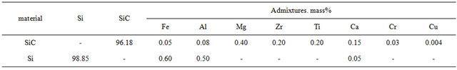
Table 1. Chemical composition of silicon carbide and silicon, mass%.
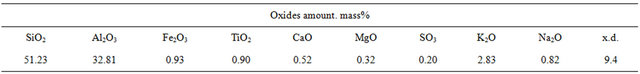
Table 2. Chemical composition of Chasov-Yar refractory clay, mass%.
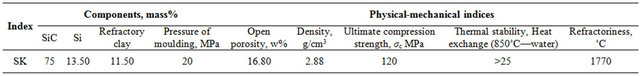
Table 3. Material composition of the initial charge and properties of the received samples.
Cylinders of d—15 mm and h—15 mm were burned in technical nitrogen area at 1000˚C; 1100˚C; 1200˚C, 1300˚C, and 1400˚C temperatures in furnace with silicon carbide heaters, grade TK 30-200. Nitrogen is supplied to furnace from the tank via rubber pipe, passing drexel in the entrances regulating nitrogen speed coming out of tank. Drexel with water mounted on furnace exit regulates pressure in furnace so that the speed of nitrogen coming out of pipe is less than the speed of nitrogen entered into reaction pipe. Delay time at the final temperature was 2 hours while speed of temperature rise was 250˚C/hr.
Technical nitrogen contains definite amount of oxygen - approximately 5% - 6%. Our purpose was to determine its effect on physical-chemical processes occurring at the production of refractory and to establish, respectively, the type of the received binder.
Investigation of samples was generally performed with X-ray phase (DRON 3 device) and microscopic analysis.
The samples burned at 1000˚C - 1100˚C are characterized with low strength and their surface is clean. According to microscopic description they generally are construed of silicon carbide high relief grains of 20 - 50 micron, its compacting combined mass is construed of crystalline silicon particles and amorphized refractory clay mixture which under double action of microscope beam is characterized with isotropy.
Figures 1(1) and (2) gives the results of X-ray phase analysis of these samples. X-ray clearly show that phase transition processes are more directed to oxidation due to which diffraction maximums are characterized with the following reflection reflexes: α-SiC (silicon carbide) dhkl 2.625 - 2.627; 2.573; 2.511 - 2.515; 2.360; 2.180; 1.539 Å. Crystalline silicon dhkl 3.130; 1.909 - 1.910; 1.635 Å; SiO2 (quartz) dhkl 3.34; 2.28; 2.45; 1.815 Å. and amorphized clay.
As is seen from the maximums of diffraction reflection the components comprising the samples burned in nitrogen medium at 1000˚C are unreactable and unchangeable resulting in clean and easily breakable surface. The maximums of diffraction reflection of the sample burned at 1100˚C (Figure 1(2)) show that oxidation of crystalline silicon occurs there due to which with the decrease of intensity of its characteristic line dhkl 3.13 Å a new formation dhkl = 4.09 Å appears there, the intensity of which is still more growing with the increase of burning temperature to 1200˚C and equals dhkl = 4.09 Å. (Figure 1(3)).
Evidently, oxidation of crystalline silicon with creation of SiO2 happens at the expanse of technical nitrogen containing oxygen. In the sample burned at 1300˚C this process is already lessened and we observe creation of silicon oxynitride, Si2ON2, and as is seen from Figures 1(3) and (4) it begins at 1200˚C and at 1300˚C the reflexes of diffraction reflection are noticed: dhkl—4.70; 4.41 - 4.43; 3.34 - 3.35; 2.414 - 2.420 Å, which is increased till 1420˚C (Figure 1(5)).
This process can be expressed with the following reaction:
3Si + SiO2 + 2N2 → 2Si2ON2
According to microscopic description the samples burned at 1200˚C - 1300˚C are of sufficient strength and on their surface a thin vitreous film is observed, sometimes with white coarse surface. According to microscope transmitting beam the sample consists of bluish high relief silicon carbide crystals of the same size and number as in samples burned at 1000˚C - 1100˚C. SiC binder mass is constructed of silicon oxynitride and products received as a result of phase transformation of burned Chasov-Yar clays which at microscopic intercrossing makes aggregately polarized fine grain mass. At 1200˚C - 1300˚C clay makes vitreous phase and new mullite formations, from diffraction reflection maximums of which dhkl (mullite)—3.41 - 3.42; 2.208 - 2.214; 5.37 - 5.41 Å are noted.
Thus, at burning of the above mentioned mixture in technical nitrogen area the refractory composite of silicon carbide with complex: oxynitride, alumosilicate and silica binder are received.
Chemical processes happening at binder receipt and the effect of burning regime on the composition of the received binder were studied with introduction of Al2O3 nano powder and the above mentioned components into the composition.
Aluminum oxide, grade GT3000SU, is the product of German company “ALCOA”. Its specific surface is BET = 7.1 m2/g, average size of primary grains D50 = 0.435 mkm. The properties of samples received with variation of Al2O3-SiC and Al2O3-Si proportions, the type of the received binder and its composition are studied. Mixture compositions at variation of Al2O3-SiC proportions and some characteristics are given in Table 4.
It was stated that complex binder has been formed the
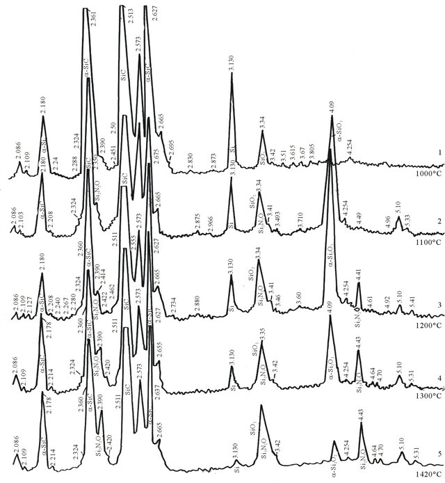
Figure 1. X-ray of silicon carbide, silicon and refractory clay mixture burned in technical nitrogen area at 1000˚C - 1400˚C: (1) 1000˚C; (2) 1100˚C; (3) 1200˚C; (4)1300˚C; (5) 1420˚C.
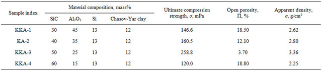
Table 4. Mixture compositions and some characteristics.
main composite components of which are mullite (3Al2O3·2SiO2) and silicon oxynitride (Si2ON2). By comparison of these data to the received silicon carbide refractory composite which did not contain Al2O3 it is clear that SiC with complex binder contained silicon oxynitride, small amount of mullite and SiO2, i.e. on addition of aluminum oxide to SiC-Al2O3 composite SiO2 phase composition was excluded. Instead, the amount of Si2ON2 and mullite has increased. X-ray (Figures 2(1) and (2) shows their characteristic lines with higher intensity which undoubtedly has been reflected on the properties of the received composite (Table 4).
In order to determine temperature of components production of SiC-Al2O3 binder the samples made of the same mixture were burned at 1000˚C and 1200˚C temperature.
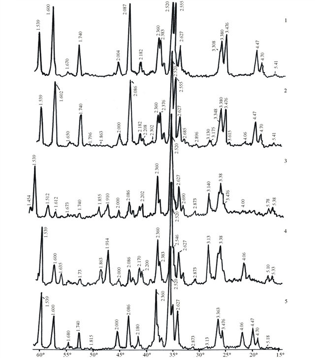
Figure 2. X-ray of KA-3 composition samples received at thermal treatment at 1420˚C with different regimes. (1) Inner layer of the sample received at burning with I regime; (2) Outer layer; (3) With III regime; (4) With V regime; (5) With IV regime.
The X-ray of sample burned at 1000˚C (Figure 3) shows the characteristic lines of silicon carbide dhkl, 2.627; 2.52; 2.36; 2.182; 2.00; 1.676; 1.54 Å. α—Al2O3 dhkl, 3.476; 2.555; 2.376; 2.086; 1.74; 1.60 Å, crystalline silicon—dhkl, 3.132; 1.319; 1.638 Å, quartz (SiO2)—dhkl, 4.254; 3.348; 2.454; 1.816 Å, while the X-ray of the sample burned at 1200˚C shows the peaks of the received silicon oxynitride—dhkl, 4.67; 4.41; 3.348; 2.43; 2.086 Å and mullite—dhkl, 3.43; 2.89; 2.52; 2.21; 1.83 Å.
SiO2 received at 1000˚C is possibly the product of partial oxidation of silicon introduced into the mixture at the expense of technical nitrogen containing oxygen. In our opinion at 1200˚C the following reaction takes place with production of oxynitride:
The analysis of the obtained results shows that on the X-ray of the sample burned with IV regime the main phases are SiC—dhkl 2.627; 2.52; 2.36; 2.18; 1.539 Å, α— Al2O3 dhkl, 3.476; 2.547; 2.39; 2.389; 2.086; 1.74; 1.60 Å, silicon oxynitride—dhk 4.70; 4.47; 3.363; 2.422 Å and mullite—dhk 2.685; 2.52; 2.422; 2.208 Å (Table 5).
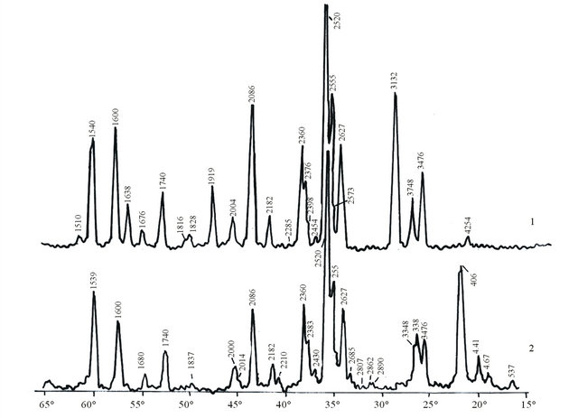
Figure 3. X-ray of KA-3 composition samples burned at 1000 and 1200˚C. (1) 1000˚C; (2) 1200˚C.
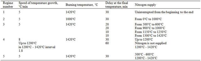
Table 5. The regime of sample thermal treatment.
By variation of Al2O3-Si proportions to receive composites we made up mixtures the material composition of which is given in Table 6. MgO—1 mass % and Y2O3— 1.5 mass % were added to all mixture above 100%.
From the given components the cylindrical samples were molded by semidry method under 20 mPa pressure. After drying they were burned in furnace in technical nitrogen medium at 1420˚C temperature with 1 hour delay.
The main properties of burned samples were checked according the respective State Standards, the results are given in Table 7.
The samples received with addition of Al2O3 are covered with glossy film. The surface of KN4 samples is coarse. Splinters are not glossy.
To define phase composition of the received composites X-ray structural analysis was done.
At the introduction of Al2O3 into SiC-Si mixture and further burning in technical nitrogen area the binder composition has changed. It consists of silicon oxynitride and mullite.
The temperature of binder creation in SiC-Al2O3 composite is 1200˚C.
SiC-Al2O3 composite compared to SiC composite is characterized with higher mechanical strength.
Phase composition of the received composite and respectively, its properties vary at alteration of thermal treatment regime [15-18].
Nitriding process in SiC-Al2O3 composite occurs in the entire layer of the sample.
At variation of SiC-Al2O3 proportion the better results are obtained in case of the following proportions: SiC— 50%; Al2O3—25%; Si—13%; clay—12%.
In case of Al2O3-Si proportions variation: SiC—40%; Al2O3—35%; Si—15%; clay—10%. i.e. to receive SiCAl2O3 composite the optimum composition is: SiC—40%; Al2O3—25% - 35%; Si—13% - 15%; clay—10% - 12%.
For testing water resistance the samples—cylinders with dimensions d—20 mm and h—15 mm were prepared from the following mixtures: SK, KN1, KN2, KN3, KN4 (Table 8).
Samples were molded with semidry method on hydraulic press under 20 mPa. After drying they were burned in a special stand in nitrogen medium not purified from (technical) oxygen.
Acid resistance was determined in concentrated sulfuric acid (ρ—1.84). For this, samples were prepared (dimensions: d—20 mm and h—15 mm) from the following mixtures (Table 9) SK, KN1, KN2, KN3, KN4.
The results of acid resistance of composites are given in Table 9.
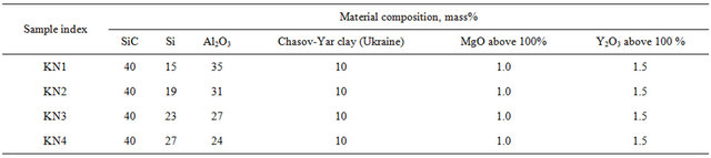
Table 6. Compositions of Si-Al2O3 mixture at proportion variation.
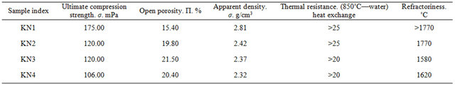
Table 7. Physical-chemical characteristics of KN1-KN4 composites.
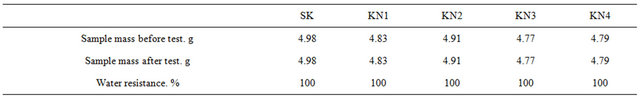
Table 8. Water resistance results.
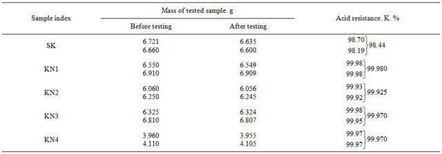
Table 9. The results of composites acid resistance (H2SO4, ρ = 1.84 g/cm3).
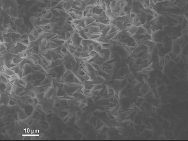
Initial, as well as, chemical resistance (water and acid resistance) of composites KN1, KN2 were studies with electron microscopic method at different magnifications (X1000, X3000).
According to electron microscopic pictures the surface of initial samples is not characterized with explicitly formed crystal structure. After treatment in water and, particularly, in sulfuric acid the picture is changed. We observe rather more explicit crystals (Figure 4(a)) compared to initial samples, their forms and density increaseing from water treated (Figure 4(b)) to acid treated (Figure 4(c)) ones. This picture is more clear in case of magnification (X3000; Figure 5).
This can be explained by the fact that the surface of composites initial samples are covered with thin vitreous film (5 - 150 nm), which is stronger effected with corrosive media than crystalline part. As a result, in microscope pictures, crystals fixing occurs with vitreous film leaching which being negligible is not expressed in mass losses.
At the determination of slag resistance it was considered that metallurgical slags at capillary suction practically do not penetrate into pores with less than 5 mkm radius [15], i.e. refractory materials are not characterized with total porosity. For the structure of porous materials the most important characteristic is pore size.
That’s why for determination of slag resistance of the composites received by us it was necessary to determine pore sizes and pore volume of these composites. KN3, KN4 composite samples have been chosen.
We used the instrument: Pascal 240. The tests were held at the ceramic department of Clausthal Technical University, Germany. The results are presented in Figures 6 and 7.
Pore sizes are studied with this method.
As is seen from Figure 6, sample KN3 does not contain pores with radius 100 nm and, of course, in this case its porosity equals to zero, pore radius growth occurs from 100 nm and alongside with radius increase to 1000 nm sample porosity also increases. Pores with radius from 800 nm to 2000 nm are in maximum amount in the sample and, respectively, in this interval porosity sharply increases, it achieves 100 mm3/g. With further increase of radius their number decreases and in the picture pore volume growth is also slowed down. Then pores of 5000 nm radius practically do not occur and porosity is also unchanged (Figure 6).
The graph in Figure 7 shows that sample KN4 does not contain pores with radius up to 400 nm, with the increase of pore radius from 400 nm to 5000 nm the volume increases. Pore radius increase occurs at 5000 nm to 10,000 nm but the number of pores with such radius decreases, therefore volume increase is comparatively negligible. The pores with radius over 10,000 nm are also quite insignificant and volume also increases respectively. Total volume of pores achieves 110 mm3/g, and in case of 1000 nm it equals to 8 mm3/g.
Unlike sample KN3 in KN4 pores of 1000 nm radius are insignificant and begin to grow from 1000 nm, while in KN3 1000 nm radius pores are in maximum amount and from 15,000 nm begin to decrease. Maximum volume in KN3 is 100 mm3/g and in KN4—110 mm3/g.
In refractory materials pores are conventionally divided according to size in the following form [16]:
Macro pores 1.7 - 170 mkm Transient 0.03 - 1.7 mkm Micro pores < 0.03 mkm The survey of Table 10 and Figures 6 and 7 shows that the composites KN3 and KN4 mainly contain transient and macro pores. In these samples maximum size of macro pores is 6000 nm [19]. The most part is from 1000 nm to 5000 nm.
Slag resistance, in our case, was defined by method of pellets which enables to show well the breaking character of refractory material in relation of the peculiarities of its structure.
 (a)
(a)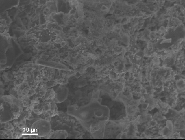 (b)
(b)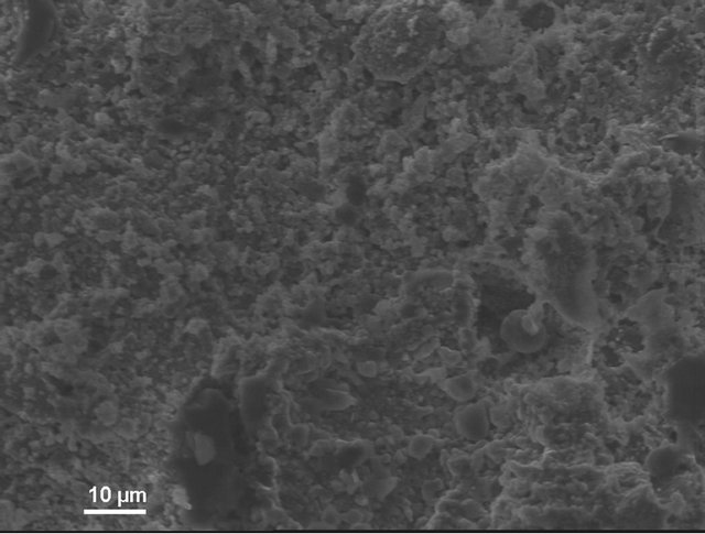 (c)
(c)
Figure 4. KN1-1000X. (a) Initial sample; (b) Sample after test for water resistance; (c) Sample after test for acid resistance.
 (a)
(a)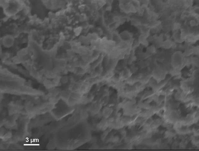 (b)
(b)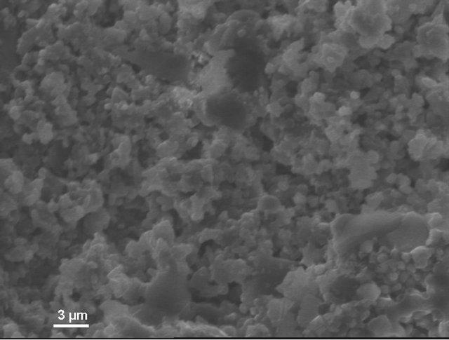 (c)
(c)
Figure 5. KN1-3000X. (a) Initial sample; (b) Sample after test for water resistance; (c) Sample after test for acid resistance.
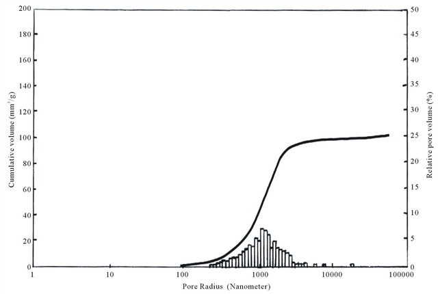
Figure 6. The relation of volume fraction and total volume of KN3 composite pores to pores radius.
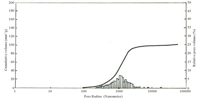
Figure 7. The relation of volume fraction and total volume of KN4 composite pores to pores radius.
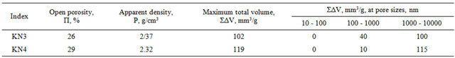
Table 10. Composites porosity and pores total volume.
For experiment the samples of size d—20 mm and h— 15 mm were prepared from mixtures KN3 and KN4, were molded with semidry method under 20 mPa pressure and after drying were burned at 1420˚C with one hour delay at the end temperature.
Open-hearth slag pellets were likewise molded with semidry method under 10 mPa pressure and were placed on refractory material samples—cylinders and then thermally treated in furnace at 1450˚C for 2 hours. The slag treated samples were cut along the axis and then corrosion depth was determined with caliper as the distance from the surface on which samples-tablets were placed to the boundary of slag distribution. The quality of material texture is worse as quickly and as more slag penetrates into refractory. When the surface of refractory-to-slag contact increases rapidly material corrosion and erosion also increase.
Below we offer open-hearth slag composition and the results of determination of slag resistance of refractory composites KN3 and KN4 (Tables 11 and 12).
As is seen from the results (Table 12) silicon carbide refractory composites are stable to open-hearth slags. The samples are never etched with slag, saturation diameter of all samples is equal to zero, as to saturation depth for KN3 and KN4 samples they, respectively, are 2 and 3 mm. Pore radii are within 800 - 4000 nm and 1000 - 6000 nm, respectively (Figure 6 and 7).
In order to determine crucible metal resistance the following nonferrous metals were chosen: aluminum, tin, lead, brass, bronze and copper. The pieces of these metals were placed in burned crucibles. To avoid oxidation of metals with air oxygen the crucibles heated to metal melting temperature were taken out of sillite furnace and metal surface was covered with friable coke layer. Then crucible was again placed in the furnace. Test temperature slightly exceeded metal melting temperature. For each test four crucibles were placed in the furnace. Two of them were removed from the furnace after 10 hours and the other two—after 40 hours of testing.
Cooled crucibles were freed from metals and they were visually surveyed. Table 13 gives the results of crucible test which makes clear that as a result of 10 and 40 hours testing refractory crucibles are stable to the above mentioned metals and no metal traces are noticed on crucibles surface [20-28].
3. Conclusions
1) Chemical processes having place at burning of silicon carbide, silicon and clay mixture in technical nitrogen
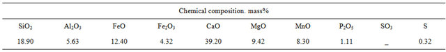
Table 11. Open-hearth slag composition.
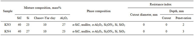
Table 12. Slag resistance of refractory composites received on the basis of silicon carbide.
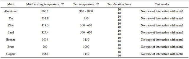
Table 13. The results of testing of refractory KN1 composite in nonferrous metals.
medium and the main properties of the received composites are studied.
2) It is stated that at burning in technical nitrogen medium silicon carbide composite with complex binder is received the main phases of which are: Si2ON2, 3Al2O3∙2SiO2 and SiO2.
3) SiC composites burned in pure and impure (technical) nitrogen medium do not differ in main properties.
4) SiC-Al2O3 composite is studied and the type of binder and its composition are stated.
5) SiC-Al2O3 composite is received with complex binder. Unlike SiC composite the binder does not contain SiO2. The increased amount of mullite instead of silica (SiO2) in binder is conditioned by the fact that the part of added Al2O3 was added to SiO2 forming 3Al2O3∙2SiO2. The amount of silicon oxynitride (Si2ON2) was also increased. Binder formation begins from 1200˚C.
6) Nitriding process in SiC-Al2O3 composite is distributed in the whole layer of sample thickness. It is characterized with high physical-mechanical indices compared to SiC composite.
7) It is established that KN1-KN4 composites are characterized with stability to water (stability 100%), acid (99.97%), nonferrous metals and slag.
8) It is proved that the received composites can be used for preparation of protective envelope of thermocouple for measuring temperatures of ferrous and nonferrous metals melted at high temperature; for continuous measuring of temperatures of nonferrous metals and for repeated short-term measuring of ferrous metals.
4. Acknowledgements
The authors thank Prof. Dr. Jurgen Heinrich at the Institute of Nonmetallic Materials, Clausthal Technical University, Germany, for his support during fulfilling the experimental works
REFERENCES
- I. Y. Guzman, E. I. Tumakova and A. V. Fedotov, “Contrastive Researches of Some Properties of Materials on the Bases of SiC + Si3N4 and SiC – Si2N2 Composites,” Refractories, No. 3, 1970, pp. 44-48.
- T. N. Zabruskova, I. Y. Guzman and H. C. Koretnikov, “Synthesis of Silicon Oxynitride,” Refractories, Vol. 34, No. 4, 1971, pp. 55-59.
- R. A. Andriebsky and I. I. Spivak, “Silicon Nitride and Materials on Its Base,” Меtallurgia, Moscow, 1984, p. 136.
- G. V. Samsonov, O. R. Kulik and V. S. Polishchuk, “Obtaining and Methods of Analysis of Nitrides,” Naukova Dumka, Kiev, 1978, p. 317.
- G. V. Samsonov, “Nitrides,” Naukova Dumka, Kiev, 1969, p. 377.
- V. K. Kazakov, Biology bulletin of the Academy of Sciences of the USSR, Inorganic Materials, Band.3, No. 9, 1967, pp. 1661-1667.
- I. Y. Guzman, E. I. Tumakova and A. V. Fedotov, “Contrastive Studies of Some Properties of Materials Based on Compositions SiC + Si3N4 and SiC – Si2ON2,” Refractories, No. 3, 1970, pp. 44-48.
- G. V. Samsonov, “Nonmetallic Nitrides,” Metallurgia, Moscow, 1969, p. 264.
- I. S. Kainarsky, E. V. Degtyareva and V. A. Kukhtenko, “Carborundum Objects on the Bond of Silicon Nitride,” Refractories, No. 4, 1960, pp. 175-180.
- O. Jamada, K. Hirao and M. Koizumi, “Combustion Synthesis of Silicon Carbide in Nitrogen Atmospfere,” Journal of the American Ceramic Society, Vol. 72, No. 9, 1989, pp. 1735-1738.
- I. S. Brokhin and V. F. Funke, “Receipt and Research of Some Properties of Ceramics from Silicon Nitride,” Refractories, No. 12, 1957, pp. 52-56.
- V. A. Novikov, V. G. Аbbakumov, L. V. Miroshnichenko and S. I. Romanov, “Effect of Temperature on the Process of Silicon Nitriding,” Refractories, No. 1, 1993, pp. 14- 17.
- K. S. Kutateladze, E. N. Zedginidze, N. S. Nizharadze and E. M. Vasserman, “Thermocouple Adapters for Measuring Liquid Aluminum,” Nonferrous Metals, No. 7, 1970, pp. 5-7.
- I. Y. Guzman, M. S. Freifeld and A. K. Karklot, “Indices (Significance) of Technological Factors at Manufacturing and Exploitation of Articles Made of Silicon Nitride,” Refractories, No. 7, 1975, pp. 23-29.
- W. Kollenberg, “Technishe Keramik,” Vulkan-Verlag, Essen, 2004, pp. 249-280.
- J. Schilm, M. Herrmann and G. Michael, “Corrosion of Silicon Nitride in Acids,” Journal of the European Ceramic Society, Vol. 23, No. 3, 2003, pp. 577-584. doi:10.1016/S0955-2219(02)00375-8
- T. Hollstein, T. Grass, K. Bundschuh and M. Schutze, “Das Korrosionsver Halten Unterschidlicher Siliciumnitride in Waprigen Loesungen,” Keramishe Zatshrift, Vol. 50, No. 2, 1998, pp. s.416-s.421.
- P. Budnikov and F. Kharitonov, “Ceramic Materials for Aggressive Media,” Stroiizdat, Moskow, 1971.
- I. S. Kainarski and E. V. Degtyareva, “Carborund Refractories,” Metalurgizdat, Kharkov, 1963, p. 197.
- Z. Kovziridze, F. Kharitonov and E. Medvedovski, “Ceramic Electrical Insulating Materials Working in Aggressive Media,” Journal of Georgian Ceramists Association “Ceramics”, Vol. 1, No. 9, 2003, pp. 3-11.
- K. G. Nickel and Y. G. Gogotsi, “Corrosion of Hard Materials,” In: R. Riedel, Ed., Ceramic Hard Materials, Wiley-VCH, Weinheim, 2000, pp. 140-182.
- G. Ulig, “Corrosion of Metals (Trans. from German),” Metallurgy, Moskow, 1968, p. 308.
- K. Kao and V. Huong, “Electron Transport in Solids (Trans. from Engl.),” MIR, Moskow 1984, p. 352.
- A. A. Popov, N. Y. Rapoport and G. E. Zaikov, “Corrosion of Oriented and Stressed Polymers,” Chemie, Moscow, 1987, p. 232.
- J. Herwood, ”Effect of Nuclear Radiation on the Materials,” Ship Building Industry, (Transl. from Engl.),” Leningrad, 1962, 300 pp. (Rus)
- L. L. Brogina, “Engineering of Enamel and Protector Coating,” Handbook, KPI, Kharkov, 2003.
- M. Mshvildadze, “The Production of Chemically Stable Glasses for Four Components System R20-MnO-B20- Si02,” Candidate Thesis, GTU, Tbilisi, 2005.
- A. Sarukhanishvili, T. Cheishvili and Z. Kovziridze, “The Theoretical Principles of Composition Material Obtaining,” Georgian Technikal University, Tbilisi, 2008.