Optics and Photonics Journal
Vol.3 No.6A(2013), Article ID:38501,6 pages DOI:10.4236/opj.2013.36A004
Development of a Novel Green-Emitting Phosphate Phosphor KSrY(PO4)2:Eu2+
Institute of Multidisciplinary Research for Advanced Materials, Tohoku University, Sendai, Japan
Email: *kakihana@tagen.tohoku.ac.jp
Copyright © 2013 Akiko Saito et al. This is an open access article distributed under the Creative Commons Attribution License, which permits unrestricted use, distribution, and reproduction in any medium, provided the original work is properly cited.
Received June 20, 2013; revised July 22, 2013; accepted August 23, 2013
Keywords: Phosphate Phosphor; Eu2+-Activation; Green Emission
ABSTRACT
In this study, fluorescence characteristics were evaluated by synthesizing Eu2+ doped samples for phosphates of various compositions. The study led to a green light emitting KSrY(PO4)2:Eu2+, which is rare for a phosphate phosphor. KSrY(PO4)2:Eu2+ had an excitation band between 250 and 450 nm and emitted green light, reaching an emission maximum at 520 nm. As this result suggests that excitation by a near-ultraviolet LED is possible, KSrY(PO4)2:Eu2+ could be useful as a phosphor for white LEDs.
1. Introduction
White LEDs have been drawing attention in recent years owing to their useful properties, including energy conservation, compact size, and long life. The currently widely popular two-wavelength type white LEDs comprising the blue LED (InGaN) and yellow phosphor Y3Al5O12:Ce3+ (YAG:Ce3+) have imperfections such as poor color-rendering properties and highly correlated color temperature, as they lack green and red components. In order to express white light that is close to natural light, the emissions of the green and red color components must be compensated. The solutions include construction of a three-wavelength type white LED consisting of a near-ultraviolet LED and red, green and blue phosphors. In order to realize the three-wavelength type white LED, we need to overcome a significant challenge of developing a novel phosphor that can be excited by a near-ultraviolet LED.
As fluorescence characteristics of phosphors strongly depend on activators and host crystals, their selection is very important. Because Eu2+ shows a wide range of emission based on 4f65d1-4f7 transition, and its excitation/emission characteristics vary significantly depending on the type of the host crystal, it has widely been used as an activator. Oxides, oxynitrides, and nitrides that contain silicon or aluminum have been actively studied as Eu2+-activated phosphors in the past. However, there are relatively few reports of Eu2+-activated phosphors for phosphates. Generally, phosphates are physically and chemically very stable, adjusting their particle size is simple and the conditions for their firing temperatures are relatively mild [1,2], so they could be useful as a host crystal of phosphors. The difficulty that phosphate phosphors have in emitting light at long wavelengths has been recognized because many Eu2+-activated phosphate phosphors, such as KSrPO4:Eu2+ [3,4], LiCaPO4:Eu2+ [5], and Ca2Sr(PO4)2:Eu2+ [6] emit purple and blue light. However, recently there have been reports of yellow glowing phosphate phosphors (Sr8MgGd(PO4)7:Eu2+ [7], Sr8MgLn(PO4)7:Eu2+ (Ln = Y, La) [8] and Ba2Mg(PO4)2:Eu2+ [9]) and a red glowing phosphor (Ca4(PO4)2O:Eu2+ [10]). Phosphates can therefore be considered a material group with a potential to become hosts for phosphors that emit light at long wavelengths.
We conducted this study aiming to develop a novel Eu2+-activated phosphate phosphor. In searching for a new phosphate phosphor, we picked up known phosphates from a database. Among these phosphates we further extracted phosphates whose Eu2+-activated fluorescence characteristics had not been reported previously and created their library. For the phosphates in the library, we prepared Eu2+-activated phosphor samples using a parallel solution synthesis method in combination with the amorphous metal complex (AMC) method [11] and using a solid-state reaction method to examine their fluorescence characteristics. A new phosphor, KSrY(PO4)2:
Eu2+, which emits green light, a rarity among phosphate phosphors, was discovered as a result, and the report is provided herein.
2. Experiments
KSrY(PO4)2:Eu2+ was synthesized by using the amorphous metal complex (AMC) method and the solid state reaction (SSR) method. Based on the chemical compositional formula, KSr1−xEuxY(PO4)2, replacement of Eu2+ was performed at 0.5 - 10 atom% to Sr2+. In this paper, unless otherwise specified, 1% displacement samples are used. The synthesis procedure using the AMC method is shown in Figure 1. The AMC method involved first mixing the aqueous solutions of citric acid and metallic nitrates according to the stoichiometric proportions and then heating them at 80˚C to form metal complexes. Here, the ratio of citric acid:metal was set to 4:1. The ethylene glycol phosphate oligomer [12], which is a phosphorus source, was then added. This mixed solution was heated at 120˚C to polymerize, and a gelatinous material was obtained. The obtained gelatinous material was heated at 450˚C for 2 h, then heated at 550˚C for 10 h in the atmosphere to perform heat decomposition, and then fired at 800˚C for 3 h to obtain the precursor. The obtained precursor was then reduced by 1000˚C to 1100˚C for 3 h in H2 (4%)/Ar to obtain the final product. The synthesis procedure using the SSR method involved mixing K2CO3, SrCO3, Y2O3, NH4H2PO4, and Eu2O3 according to the stoichiometric proportions, firing them at 800˚C for 3 h in the atmosphere, and then reducing them in an atmos-
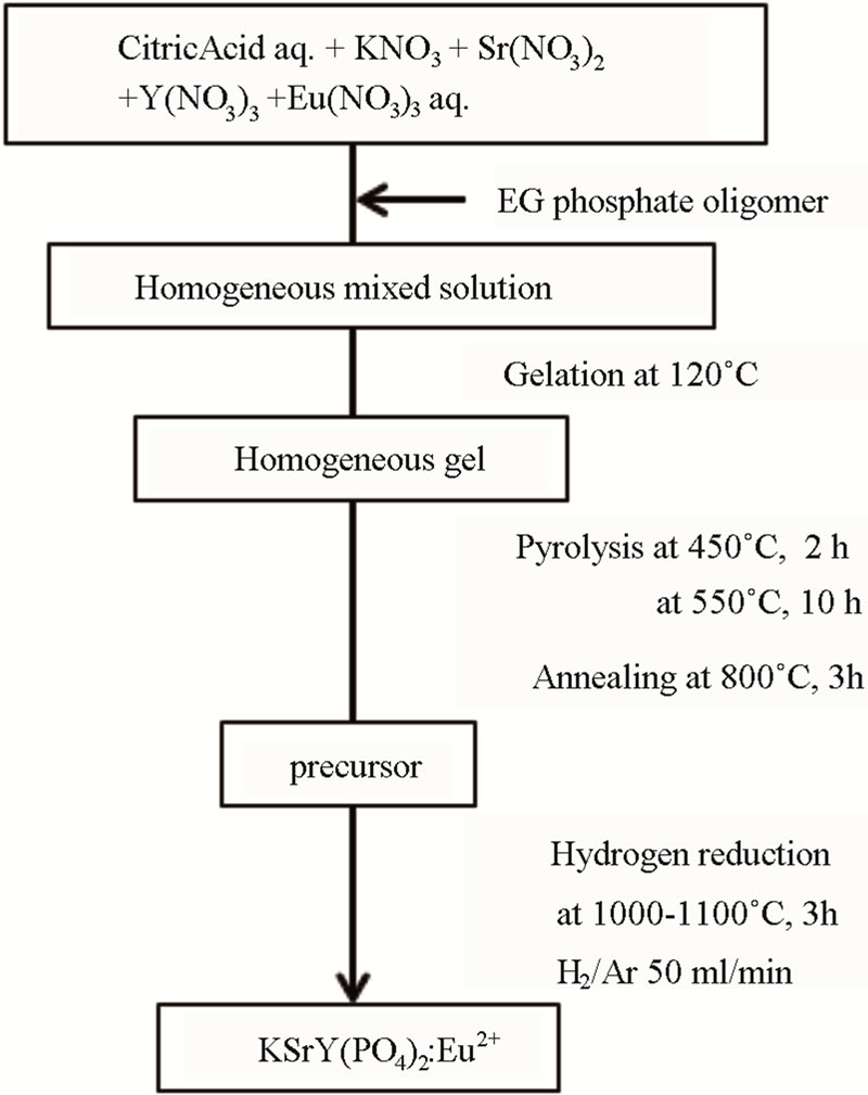
Figure 1. Flowchart of KSrY(PO4)2:Eu2+ synthesis by AMC method.
phere of H2 (4%)/Ar under various conditions. The obtained specimen was evaluated by a powder X-ray diffractometer measurement, an SEM-EDS measurement, and a fluorescence spectrum measurement.
3. Results and Discussion
3.1. Comparison of SSR Method and AMC Method
The diffraction patterns of the specimen synthesized by the AMC and the SSR methods are shown in Figure 2. The triangle and circle in the figure indicate the diffraction peaks of impurity phase, Sr3Y(PO4)3, and of the unknown phase, respectively. The standard diffraction pattern of KCaNd(PO4)2 [13], which has the same structure type as KSrY(PO4)2, is also shown in the same figure. All the samples contained some unknown phases, but KSrY(PO4)2, which was the target substance, was formed as the main phase. Among the samples synthesized with the AMC, those reduced at 1000˚C did not show impurity-origin peaks other than unknown phases, but reduction at 1100˚C newly formed impurity phases of Sr3(PO4)2 and Sr3Y(PO4)3. This points to the fact that the Sr3Y(PO4)3 phase, which does not include any K, was formed, as K having highly volatile nature volatilized with the rise in temperature. On the other hand, for the case of the SSR method, no Sr3Y(PO4)3, which is an impurity, was formed even when the reduction was performed at 1100˚C, and a practically single phase KSrY (PO4)2 was obtained. This indicates that K tends to be less likely to volatilize with the SSR method. This is probable because the precursors prepared by the AMC were formed with particulates with a larger specific surface area, resulting in more significant volatilization of K.
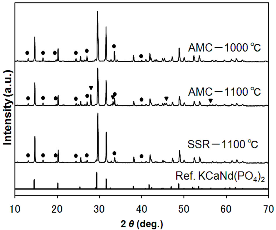
Figure 2. XRD patterns of the samples prepared by AMC and SSR methods. Symbols indicate diffraction peaks from impurities; circles: unknown phase, triangles: Sr3Y(PO4)3.
3.2. The Excitation and Emission Characteristics of KSrY(PO4)2:Eu2+
The results obtained from the fluorescence spectrum measurement taken from the specimens synthesized with the AMC method as well as the SSR method are shown in Figure 3. Spectra with similar shapes were obtained for all specimens. KSrY(PO4)2:Eu2+ had an excitation band between 250 and 450 nm and emitted green light, reaching an emission maximum at 520 nm. Many previously reported Eu2+-activated phosphate phosphors, such as KSrPO4:Eu2+, LiCaPO4:Eu2+ and Ca2Sr(PO4)2:Eu2+ emit blue light by ultraviolet excitation. The fact that KSrY(PO4)2:Eu2+ was discovered by this study to emit green light can be considered to be a very interesting outcome for a phosphate phosphor. The specimens synthesized by the AMC method and reduced at 1100˚C indicated more intense light emissions than those processed at 1000˚C. The specimens synthesized by the SSR method and reduced at 1100˚C indicated a light emission intensity that was approximately 1.7 times that of the specimens synthesized with the AMC method. The reason for higher brightness in the SSR samples could be the influence of volatilization of K. Defects could have been formed in the crystals in the samples synthesized by the AMC method due to more volatilization of K, resulting in the reduction of their emission intensity.
3.3. Optimization of Firing Conditions
As mentioned above, the SSR sample showed higher emission intensities than the AMC samples. Accordingly, we studied the synthesis conditions of the SSR method in detail. Figure 4 shows the diffraction pattern of KSrY(PO4)2:Eu2+ synthesized with a firing time of 3 h and by changing the temperature from 950˚C to 1200˚C. When synthesized at 950˚C and 1000˚C, there was some KSrPO4 as well as unknown phases, even though the main phase was KSrY(PO4)2. On the other hand, in the
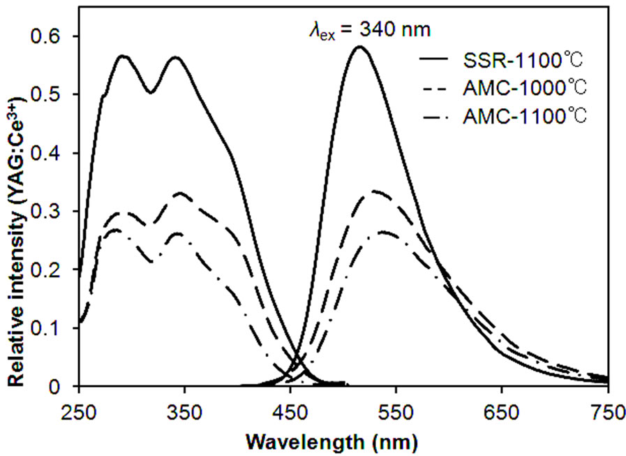
Figure 3. PL spectra of the samples prepared by AMC and SSR methods.
samples synthesized at 1100˚C, the KSrPO4 phase disappeared with the volatilization of K, and KSrY(PO4)2 was obtained almost as a single phase with a small amount of unknown phases. Further increase in the treatment temperature to 1200˚C resulted in a mixed phase of Sr3Y(PO4)3 and YPO4 and the disappearance of the KSrY(PO4)2 phase. At higher temperatures, Sr3Y(PO4)3 and YPO4, which do not contain K, were probably formed because of the significant loss of K through volatilization. Thus, firing at high temperatures was not suitable for the synthesis of KSrY(PO4)2. These results indicate that KSrY(PO4)2 of the highest phase purity can be obtained by heat treatment at 1100˚C.
The excitation and emission spectra of these samples (excluding those synthesized at 1200˚C containing almost no KSrY(PO4)2) are shown in Figure 5. The samples containing a KSrPO4 phase synthesized at 950 and
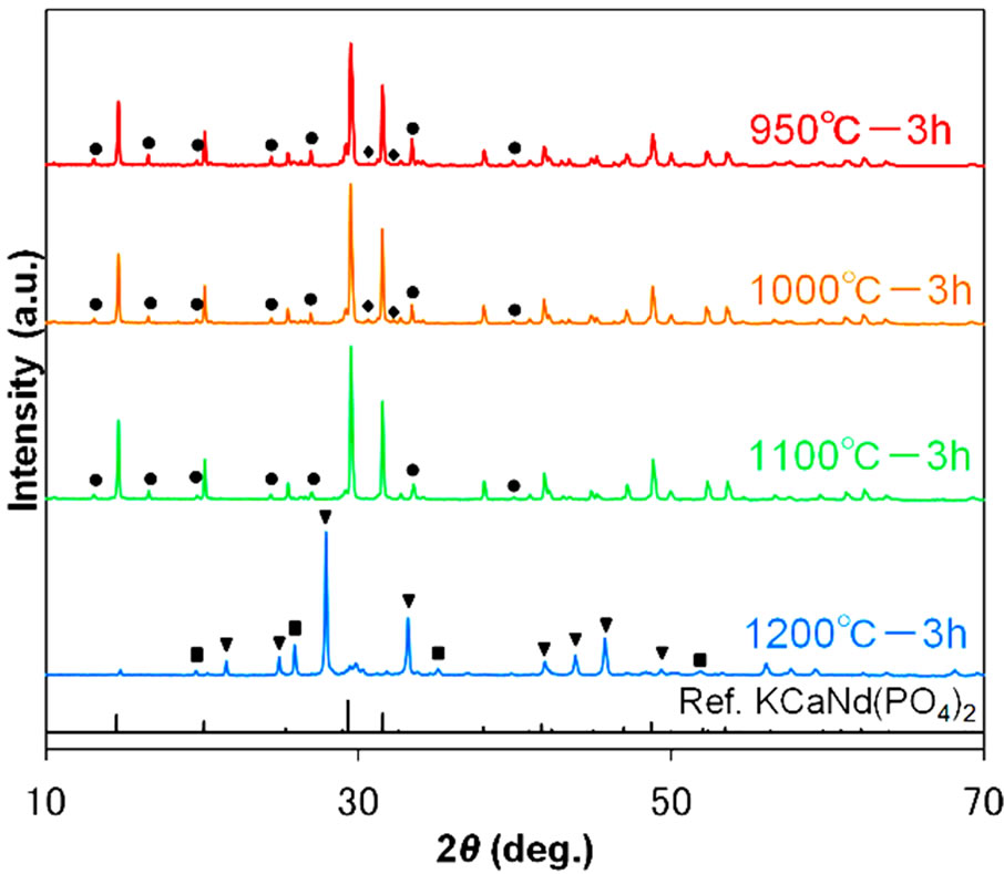
Figure 4. XRD patterns of samples various temperatures. Symbols indicate diffraction peaks from impurities; circles: unknown phase, triangles: Sr3Y(PO4)3, diamonds: KSrPO4, squares: YPO4.
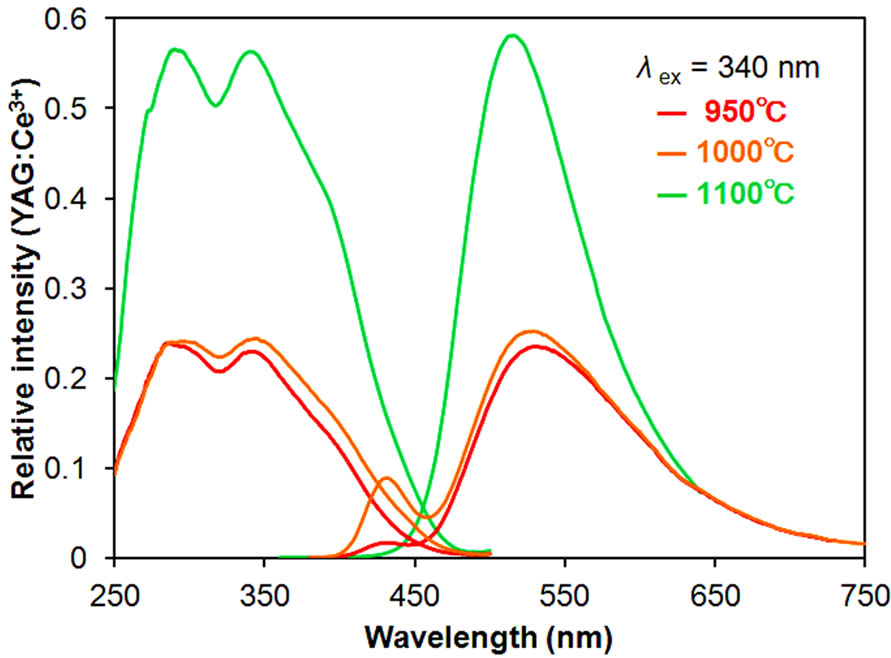
Figure 5. PL spectra of samples synthesized at various temperatures.
1000˚C had an emission derived from KSrPO4:Eu2+ near 430 nm as well as an emission peak derived from KSrY(PO4)2:Eu2+ near 520 nm. The emission intensity of the KSrY(PO4)2:Eu2+ origin near 520 nm of these samples was remarkably lower compared with that synthesized at 1100˚C. Even we excited these samples at 230 nm, sharp luminescence originating from Eu3+ was not observed. These results suggest that all Eu turned into Eu2+ with the reduction at 950 and 1000˚C. During synthesis at low temperatures, Eu does not spread easily, leading to poor dispersion of Eu in the KSrY(PO4)2 host, resulting in the local quenching due to energy transfer among Eu ions. On the other hand, the heat treatment at 1100˚C increased the dispersion of Eu2+ and reduced local quenching, resulting in a higher emission intensity. It was demonstrated that reduction at 1100˚C was suitable for the synthesis of samples with higher emission intensities. Next, the firing temperature was set to 1100˚C and samples were synthesized using various lengths of firing time.
The diffraction patterns of the samples and their excitation and emission spectra are shown in Figures 6 and 7, respectively. Even with a short firing time of 2 h, KSrY(PO4)2:Eu2+ of relatively high phase purity was obtained with formation of a small amount of unknown phases (marked with circles). On the other hand, firing for 4 h formed no unknown phases, but the diffraction intensity of the KSrY(PO4)2 phase considerably decreased, instead of which a Sr3Y(PO4)3 phase (marked with triangles) was formed . The samples with 2 and 3 h of firing time had excitation and emission spectra of a similar profile. The samples with 3 h of firing time glowed brighter than the samples with 2 h of firing time. On the other hand, the emission maximum wavelength of the sample synthesized with 4 h of firing blue sifted to 510 nm. This is because the emission of Sr3Y(PO4)3:Eu2+
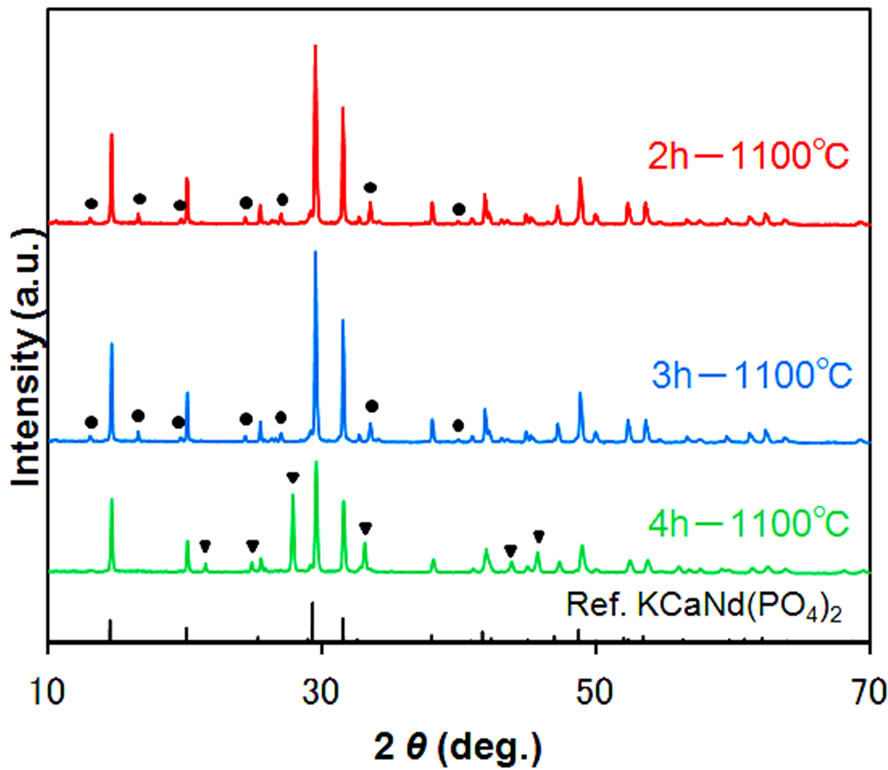
Figure 6. XRD patterns of samples synthesized at 1100˚C for different times.
(emission maximum wavelength: 490 nm) contained as an impurity phase is mixed up, in addition to the emission from KSrY(PO4)2:Eu2+. These results demonstrate that the synthesis condition to obtain a KSrY(PO4)2:Eu2+ with high emission intensity is firing at 1100˚C for 3 h.
3.4. Optimization of Eu2+ Concentration
In general, the light-emitting characteristics of the Eu2+-activated phosphors are strongly dependent on the concentration of Eu2+. An investigation was therefore conducted on the Eu2+ concentration dependence on photoluminescence properties of KSrY(PO4)2:Eu2+ phosphors. The samples were synthesized by the SSR method, firing at 1100˚C for 3 h. The results of the X-ray diffraction confirmed that the targeted phase was obtained practically in a single phase, with no dependence on the Eu2+ concentration. The excitation and emission spectra of 0.5% - 10% of the Eu2+-activated KSrY(PO4)2: Eu2+ are shown in Figure 8. The wavelength of the emitted light was 520 nm when the Eu2+ concentration was 0.5 and 1%, but shifted to 525 nm for 4 to 10%. A review of the excitation spectrum revealed that the relative intensity of the shoulder peaks at 394 nm was greater when the Eu2+ concentration was 4% or more. KSrY(PO4)2: Eu2+ exhibited maximum light emissions when the Eu2+ concentration was 1%, whereas the light emission intensity decreased uniformly when the Eu2+ concentration was further increased. The light emission intensity of KSrY(PO4)2:Eu2+ (1%) at the present point in time is 58% for the YAG:Ce3+ (P46) phosphor available on the market, while the internal quantum efficiency and absorption rate at 340 nm were 30% and 73%, respectively.
3.5. Thermal Quenching Properties
When applying phosphors for white LEDs, it is essential that the temperature dependence of the fluorescence cha-
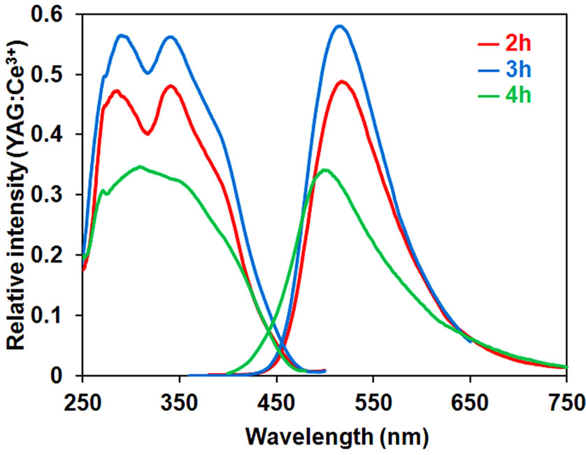
Figure 7. PL spectra of the samples synthesized at 1100˚C for different times.
racteristics is investigated, as temperature fluctuations impact the output of lightand color-rendering properties. The results of the investigation on the fluctuation of light emission intensity from room temperature to 200˚C for KSrY(PO4)2:Eu2+ (1%) are shown in Figure 9. The light emission intensity decreases as the temperature rises, reaching 57% at 150˚C. Thermal quenching has been reported to be less likely to occur when the PO4 units inside the crystal structure of the phosphate phosphor share oxygen [14]. It can be speculated that because in KSrY(PO4)2, which has the same type of structure as KCaNd(PO4)2, PO4 units exist in isolation [13], so its thermal quenching is relatively significant.
4. Conclusion
Eu2+-activated KSrY(PO4)2:Eu2+ was discovered to be a new phosphor. The new phosphor, KSrY(PO4)2:Eu2+, has an excitation band between 250 and 450 nm and emits green light, reaching an emission maximum at 520 nm. The emission intensity of KSrY(PO4)2:Eu2+ samples depended strongly on the heat treatment temperature for their synthesis. The heat treatment at 1100˚C was suitable for obtaining KSrY (PO4)2:Eu2+ with a high emis-
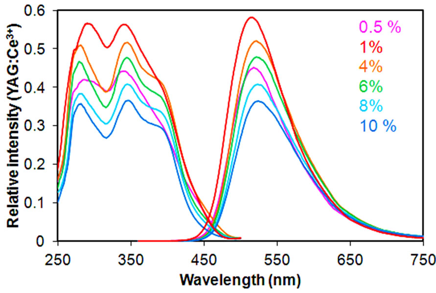
Figure 8. PL spectra of KSrY(PO4)2:Eu2+ with different Eu2+ concentration.
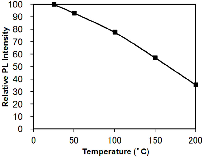
Figure 9. Thermal quenching of KSrY (PO4)2:Eu2+.
sion intensity. The optimum Eu2+ concentration for KSrY(PO4)2:Eu2+ was 1%. As described above, we were successful in our development of a green light phosphor, KSrY(PO4)2:Eu2+, which can be excited using near-ultraviolet LEDs.
5. Acknowledgements
The present work was supported by a Grant-in-Aid for Scientific Research (A) (No. 22246081) from Japan Society for the Promotion of Science, Japan.
REFERENCES
- S. Lucas, E. Champion, D. Bregiroux, D. Bernache-Assollant and F. Audubert, “Rare Earth Phosphate Powders RePO4∙nH2O (Re = La, Ce or Y). Part 1. Synthesis and Characterization,” Journal of Solid State Chemistry, Vol. 177, No. 4-5, 2004, pp. 1302-1311. http://dx.doi.org/10.1016/j.jssc.2003.11.003
- Z. C. Wu, J.X. Shi, J. Wang, M.L. Gong and Q. Su, “A Novel Blue-Emitting Phosphor LiSrPO4:Eu2+ for White LEDs,” Journal of Solid State Chemistry, Vol. 179, No. 8, 2006, pp. 2356-2360. http://dx.doi.org/10.1016/j.jssc.2006.04.030
- S. H. M. Poort, W. Janssen and G. Blasse, “Optical Properties of Eu2+-Activated Orthosilicates and Orthophosphates,” Journal of Alloys and Compounds, Vol. 260, No. 1-2, 1997, pp. 93-97. http://dx.doi.org/10.1016/S0925-8388(97)00140-0
- Y. S. Tang, S. F. Hu, C. C. Lin, N. C. Bagkar and R. S. Liu, “Thermally Stable Luminescence of KSrPO4:Eu2+ Phosphor for White Light UV Light-Emitting Diodes,” Applied Physics Letters, Vol. 90, No. 4-5, 2007, Article ID: 151108. http://dx.doi.org/10.1063/1.2721846
- C. Wan, J. Meng, F. Zhang, X. Deng and C. Yang, “An Efficient Blue-Emitting Phosphor LiCaPO4:Eu2+ for White LEDs,” Solid State Communications, Vol. 150, No. 31-32, 2010, pp. 1493-1495. http://dx.doi.org/10.1016/j.ssc.2010.05.037
- X. Wang, F. Du, D. Wei, Y. Wuang and H. J. Seo, “The Blue-Emitting Phosphor of Eu2+-Doped Ca2Sr(PO4)2,” Journal of The Electrochemical Society, Vol. 158, No. 8, 2011, pp. J264-J268.
- C. H. Huang, D. Y. Wang, Y. C. Chiu, Y. T. Yeh and T. M. Chen, “Sr8MgGd(PO4)7:Eu2+: Yellow-Emitting Phosphor for Application in Near-Ultraviolet-Emitting Diode Based White-Light LEDs,” RSC Advances, Vol. 2, No. 24, 2012, pp. 9130-9134. http://dx.doi.org/10.1039/C2RA20646C
- C. H. Huang and T. M. Chen, “Novel Yellow-emitting Sr8MgLn(PO4)7:Eu2+ (Ln = Y, La) Phosphors for Applications in White LEDs with Excellent Color Rendering Index,” Inorganic Chemistry, Vol. 50, No. 12, 2011, pp. 5725-5730.
- Z. Wu, M. Gong, J. Shi, G. Wang and Q. Su, “Dibarium Magnesium Diphosphate Yellow Phosphor Applied in InGaN-Based LEDs,” Chemistry Letters, Vol. 36, No. 3, 2007, pp. 410-411. http://dx.doi.org/10.1246/cl.2007.410
- D. Deng, H. Yu, Y. Li, Y. Hua, G. Jia, S. Zhao,H. Wang, L. Huang, Y. Li, C. Lia and S. Xu, “Ca4(PO4)2O:Eu2+ Red-Emitting Phosphor for Solid-State Lighting: Structure, Luminescent Properties and White Light Emitting Diode Application,” Journal of Materials Chemistry C, Vol. 1, No. 19, 2013, pp. 3194-3199. http://dx.doi.org/10.1039/C3TC30148F
- N. Yamatani, V. Petrykin, and M. Kakihana, “Synthesis of K3Ta3B2O12 Photocatalytic Material by Aqueous Solution-Based Process Using a Novel Water Soluble Tantalum Complex,” Journal of the Ceramic Society of Japan, Vol. 117, No. 1363, 2009, pp. 308-312.
- J. Pretula and J. Polyn, “Formation of Poly(ethylene phosphates) in Polycondensation of H3PO4 with Ethylene glycol. Kinetic and Mechanistic Study,” Journal of Polymer Science Part A: Polymer Chemistry, Vol. 46, No. 3, 2008, pp. 830-843. http://dx.doi.org/10.1002/pola.22427
- M. Vlasse, P. Bochu, C. Parent, J. P. Chaminade, A. Daoudi, G. Le Flem and P. Hagenmuller, “Structure Determination of Calcium Neodymium Potassium Double Phosphate CaKNd(PO4)2,” Acta Crystallographica Section B: Structural Science, Vol. 38, No. 9, 1982, pp. 2328-2331. http://dx.doi.org/10.1107/S0567740882008735
- A. Oki, M. Zeller, Y. Coranza, J. Luevano and A. D. Hunter, “Hydrothermal Synthesis and Structure of an Openframework Co0.7Zn1.3(PO4)2(NH3-CH2 CH2NH3) and Co6.2(OH)4(PO4)4Zn1.80, a New Adamite Type Phase,” Inorganica Chimica Acta, Vol. 360, No. 9, 2007, pp. 2917-2922. http://dx.doi.org/10.1016/j.ica.2007.02.032
NOTES
*Corresponding author.