Optics and Photonics Journal
Vol.3 No.2(2013), Article ID:32632,5 pages DOI:10.4236/opj.2013.32026
Power Tapping Function in Near Infra-Red Region Based on 45˚ Tilted Fiber Gratings
1Aston Institute of Photonics Technology, School of Engineering and Applied Science, Aston University, Birmingham, UK
2Department of Electronic Engineering, School of Information Science and Engineering, Xiamen University, Xiamen, China
3Arden Photonics Ltd., Solihull, UK
Email: *adebayae@aston.ac.uk
Copyright © 2013 Adedotun Adebayo et al. This is an open access article distributed under the Creative Commons Attribution License, which permits unrestricted use, distribution, and reproduction in any medium, provided the original work is properly cited.
Received April 10, 2013; revised May 12, 2013; accepted May 18, 2013
Keywords: Power Tapping; Tilted Fiber Grating; Polarization Dependent Loss; In-Fiber Polarizer
ABSTRACT
We report an efficient power tapping device working in near infra-red (800 nm) wavelength region based on UV-inscribed 45˚ tilted fiber grating (45˚-TFG) structure. Five 45˚-TFGs were UV-inscribed in hydrogenated PS750 fiber using a custom-designed phase mask with different grating lengths of 3 mm, 5 mm, 9 mm, 12 mm and 15 mm, showing polarization dependent losses (PDLs) of 1 dB, 3 dB, 7 dB, 10 dB and 13 dB, respectively. The power side-tapping efficiency is clearly depending on the grating strength. It has been identified that the power tapping efficiency increases with the grating strength and deceases along the grating length. The side-tapped power profile has also been examined in azimuthal direction, showing a near-Gaussian distribution. These experimental results clearly demonstrated that 45˚- TFGs may be used as in-fiber power tapping devices for applications requiring in-line signal monitoring.
1. Introduction
The tilted fiber grating (TFG) structure was first demonstrated by Meltz et al. in 1990 [1] and, in 1996, Erdogan and Sipe have given a detailed theoretical analysis on mode coupling mechanism for TFGs [2]. TFGs have been applied widely in polarization-related applications, such as polarization dependent loss (PDL) equalizer [3], in-line polarimeter [4] and polarization filters [5]. Fiber gratings with tilted structure are inherently capable of coupling light from the core mode not just to cladding but also to radiation modes in a controlled fashion, compared with long period fiber gratings (LPGs), which only couple the light to cladding modes. Hence, based on the radiation mode coupling function, TFGs may be used for power tapping applications. The first theoretical description of the power radiation property of TFG was reported by Li et al. in 2001 [6], which were based on volume current approach to explain the scattering of out-coupled light from a TFG. Various applications of power tapping have used fiber gratings with structure tilted at relatively small angles, including wavelength locking of a DFB laser and optical fiber communication network [7] and wavelength de-multiplexer [8].
However, there are two major drawbacks related to side tapping using small angle TFG, which are its backward-reflection and resonant feature on spectral response due to cladding modes coupling.
These drawbacks may be overcome by choosing relatively large angle TFGs and applying index matching gel on the fiber surface, respectively. Another work using small angle TFG reported by Rui et al. is to use a 10˚- TFG to tap the light out from the fiber side for a sensing interrogation system [9]. However, due to total internal reflection effect, the light cannot be tapped out directly, but only after immersing the grating into oil with refractive index very close to the fiber cladding. To enhance radiation power from side tapping, 45˚ tilted fiber gratings (45˚-TFGs) may be used, as such grating structures act as an in-fiber polarizer, tapping the S-polarization light out of and leaving the P-polarization travelling along the fiber. We report in this paper the fabrication of 45˚-TFGs at 800 nm wavelength range and demonstrate their distinctive polarization property and power tapping function.
2. Theory
The 45˚-TFG structures exploit the principle of light coupling from the forward propagating core mode to the radiation modes. The radiation direction of the light depends on the wavelength of the light launched into the fiber and only the light of which with the wave propagating constant satisfying the phase matching condition of the TFG will be tapped out of the fiber. The phase matching condition which describes the resonance interaction between the radiation modes, core mode and grating structure is stated in Equation (1) and also shown in Figure 1(a):
 (1)
(1)
where  and
and  are wave vectors of the radiated light, the core mode and the grating respectively.
By specifying the right parameters during TFG fabrication, direction of radiation and the wavelength of the main beam can be identified by Equation (2):
 (2)
(2)
 (a)
(a) (b)
(b)
Figure 1. (a) Vector phase matching condition for a 45˚-TFG; Inset: microscopic image of a UV-inscribed 45˚-TFG; (b) simulated ratio of radiation power of S- (solid line) and P-polarization (dash line) for a 45˚-TFG.
where  and
and ![]() are the radiation angle and the tilt angle of the grating structure. According to the total internal reflection (TIR) effect, the TFGs can be classified into three different mode coupling regimes depending on tilted angle:
are the radiation angle and the tilt angle of the grating structure. According to the total internal reflection (TIR) effect, the TFGs can be classified into three different mode coupling regimes depending on tilted angle:
1) δ < 23.1˚—backward cladding mode coupling;
2) 23.1˚ < δ < 66.9˚—radiation mode coupling;
3) δ < 66.9˚—forward cladding mode coupling.
From Equation (2), we can deduce that when δ = 45˚ (for a 45˚-TFG), the radiated light will be tapped out at 90˚ direction to the fiber, which will be ideal for sidetapped power detection. The tilt angle of the grating plane and the index modulation strength will determine the radiation coupling efficiency of the light that is tapped out. The tapping coefficient t of a 45˚-TFG can be expressed as [10]:
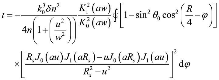 (3)
(3)
where  is the wave vector of light in vacuum,
  and n are the modulated and original refractive indices of the fiber core, a is the core radius and u and w are the waveguide parameters, J0,1 and K0,1 are the first kind Bessel function and the second kind modified Bessel function, respectively.
In Equation (3),
 where θ0 is the angle between the radiation beam and the fiber axis, which satisfies
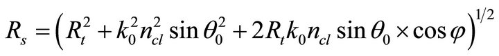
 , φ denotes the polarization of the core mode, Rt and Rg are wave vectors of the grating along the fiber axis and across the fiber cross-section and are defined as
 ![]()
 and
and , where
  is the period of grating.
Based on Equation (3), we have simulated the ratio of radiated and input power strength for Sand P-polarization for 45˚-TFGs with different modulation index changes and the results are plotted in Figure 1(b). It can be clearly seen from the figure that the tapping power efficiency can be easily controlled by fabricating the 45˚-TFGs with appropriate index modulation strength.
3. Fabrication and Polarization Property of 45˚-TFGs
The 45˚-TFGs were UV-inscribed in standard PS750 fiber (from FiberCore). Before the UV-inscription, the fiber was pre-hydrogen loaded at 80˚C for 48 h to increase its photosensitivity. The 45˚-TFG structure was fabricated using a tilted phase mask and a 244 nm UV source from a CW frequency doubled Ar+ laser (Coherent Sabre Fred). The phase mask pattern has a period of 922.46 nm and tilted at 33.7˚ with an effective area of 25 mm × 10 mm, designed to ensure the modulated index fringes are at 45˚ inside of the fiber with the central wavelength response at around 800 nm. The inset in Figure 1(a) shows the structure image of a fabricated 45˚- TFG in the fiber core captured with a microscope (Zeiss Axioskop 2 Mot Plus) with 100× oil immersion objective lens.
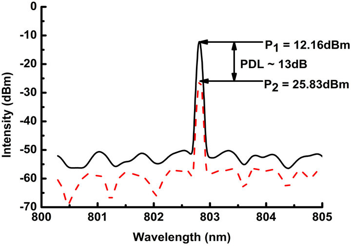
Five 45˚-TFGs of different lengths (15 mm, 12 mm, 9 mm, 5 mm and 3 mm) were fabricated under the same inscription condition (the same power level and scanning speed of the UV beam). After the inscription, the PDL property of the five 45˚-TFGs were characterized by using a single wavelength laser at 802.3 nm and the method reported in Ref. [11], showing PDL values of 13 dB, 10 dB, 7 dB, 3 dB and 1 dB, respectively. Figures 2(a) and (b) display the PDL spectra of Sand P-polarized light at 802.3 nm and the polarization distribution figure of the 15 mm long 45˚-TFG, respectively. This is a relatively strong polarised grating, showing a polarization extinction ratio (PER) of ~13 dB.
4. Power Tapping Experiment
The side tapped out light from the 800 nm 45˚-TFG was easily observed when a white light (SuperK light source from 450 nm to 2400 nm) and red light source at 633 nm were passed through the grating, as we observed the dispersion (Figure 3(c)) and diffraction (Figure 3(d)) images, respectively, on a screen placed on the side of the fiber.
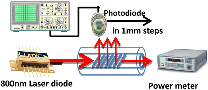
Figure 3(a) shows the experiment setup to measure the side-tapped and transmitted power from a 45˚-TFG fiber. For the measurement, the single wavelength light source we used is a 802 nm laser diode from LUMICS. An InGaA Samplified detector (700 nm - 1800 nm) from Thorlabs connected to an oscilloscope was used to measure the power from the side of the 45˚-TFG. The other end of fiber was plugged into a power-meter to measure the remaining light in the fiber core.
The side-tapped and transmitted powers of the five 45˚-TFGs with different lengths were measured at the grating start position and the results are plotted in Figure 3(b). It can be seen clearly from the figure that the shorter (i.e. weaker) grating gives less side-tapped and more transmitted power, while vice versa for the longer grating. This agrees well with the simulation results shown in Figure 1(b).
In the experiment, we also found that the side tappedout power by the 45˚-TFG varies along the grating length.
 (a)
(a)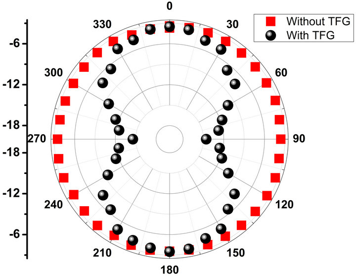 (b)
(b)
Figure 2. (a) The PDL measurement of Sand P-polarized light from the 15 mm long 45˚-TFG, showing a PDL of ~13 dB; (b) Polarization distribution figure: Red square dots showing 0 dB PDL as measured from a virgin fiber; Black circle dots showing a near-8 figure shape measured from the 15 mm long 45˚-TFG.
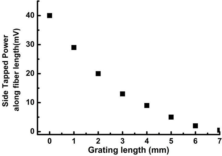
To quantitatively analyze the side-tapped power distribution along grating axial direction, the photodiode was amounted on a translation stage. Choosing the 9 mm long 45˚-TFG, by moving the translation stage in 1 mm step, the power distribution over the entire grating length was measured.
The result plotted in Figure 4(a) clearly shows that the side-tapped out power is the highest at the start position of the grating, but reduces as the photodiode scans along the grating length, showing an exponentially decreasing trend.
We further measured the distribution of side-tapped power in azimuthal direction by moving the photodiode in lateral dimension and the power profile showed a distributed near-Gaussian shape, as shown in Figures 4(b) and (c).
5. Conclusion
We have successfully demonstrated power tapping de-
 (a)
(a)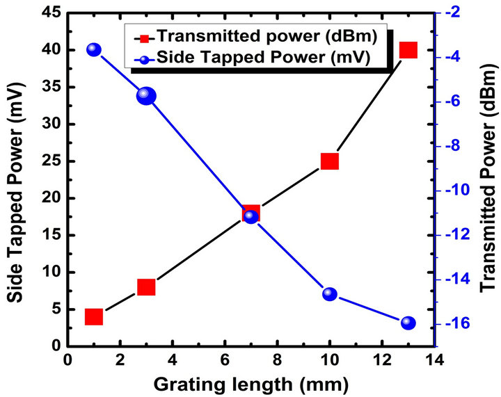 (b)
(b)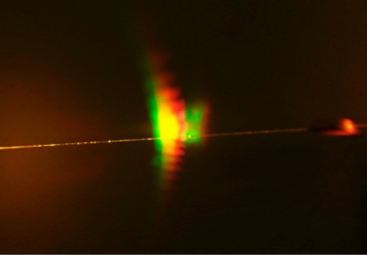 (c)
(c)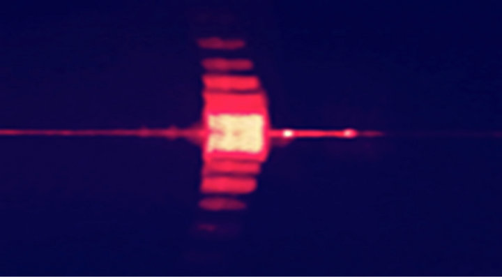 (d)
(d)
Figure 3. (a) Experimental setup for power tapping measurement; (b) The side-tapped (circle) and transmitted (square) power from the fabricated five 45˚-TFGs of different lengths; (c) Images of side-tapped out light when launched with a white (SuperK) and (d) Red light, respectively.
 (a)
(a)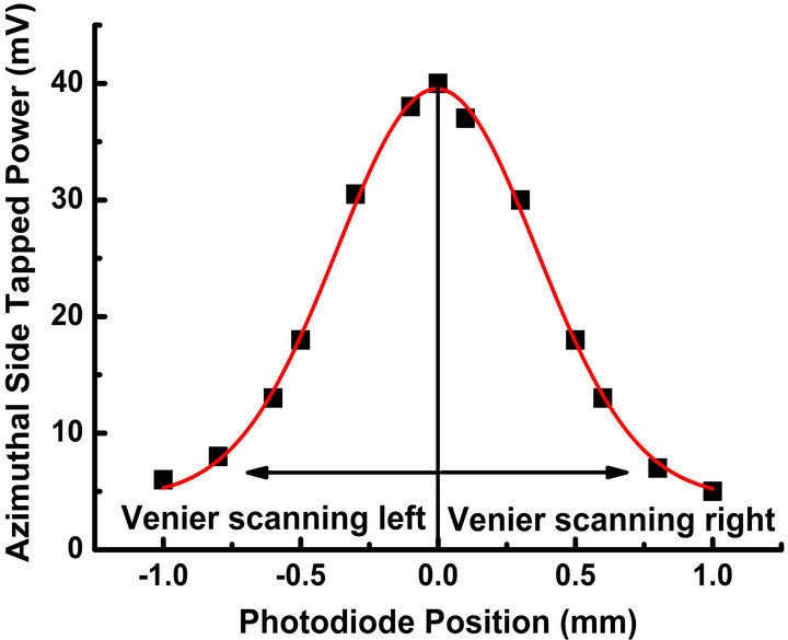 (b)
(b)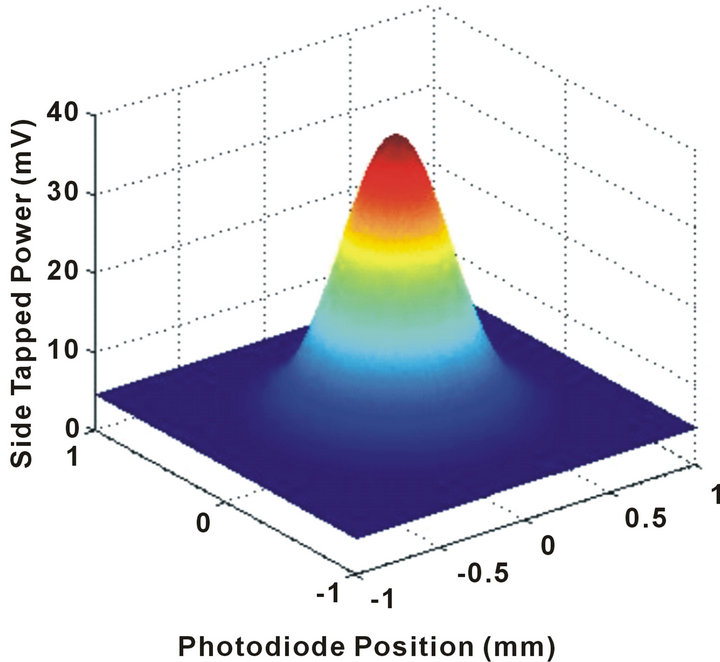 (c)
(c)
Figure 4. (a) Measured side-tapped out power along the length for the 9 mm 45˚-TFG; (b) Measured power distribution in azimuthal direction, showing a Gaussian profile; (c) Replotted measured power distribution in azimuthal direction in 3-D.
vices working at 800 nm based on 45˚-TFGs. The 45˚- TFGs of different lengths (from 3 mm to 15 mm) were UV-inscribed into hydrogenated PS750 fiber, showing different PDLs (from 1 dB to 13 dB) and revealing stronger (longer) grating tapping more light out from the fiber. We also experimentally verified that the side-tapping efficiency deceases along the grating length, thus, for a real power tapping device, a 45˚-TFG of mm length may be sufficient enough. The side-tapped power vs the strength and length of 45˚-TFG clearly shows that 45˚-TFGs are ideal power side-tapping devices and it should be possible to tap power as small as 1% out of the fiber, which can be useful in optical communication and laser systems for in-line monitoring.
6. Acknowledgements
The authors would thank for the support from EPSRC CASE studentship and all those helped for this research work.
REFERENCES
- G. Meltz, W. W. Morey and W. H. Glenn, “In-Fiber Bragg Grating Tap,” Optical Fiber Communication Conference, OFC’90, San Francisco, 23 January 1990, 1 p.
- T. Erdogan and J. E. Sipe, “Tilted Fiber Phase Gratings,” Journal of the Optical Society of America A—Optics Image Science and Vision, Vol. 13, No. 2, 1996, pp. 296- 313.
- S. Mihailov, R. Walker, T. Stocki and D. Johnson, “Fabrication of a Tilted Fiber-Grating Polarization-Dependent Loss Equalizer,” Bragg Gratings, Optical Society of America (OSA), Stresa, 4 July 2001, 3 p.
- P. S. Westbrook, T. A. Strasser and T. Erdogan, “In-Line Polarimeter Using Blazed Fiber Gratings,” IEEE Photonics Technology Letters, Vol. 12, No. 10, 2000, pp. 1352- 1354. doi:10.1109/68.883827
- G. Nemova, J. Chauve and R. Kashyap, “Design of Sidetap Fiber Bragg Grating Filters,” Optics Communications, Vol. 259, No. 2, 2006, pp. 649-654. doi:10.1016/j.optcom.2005.09.064
- Y. Li, M. Froggatt and T. Erdogan, “Volume Current Method for Analysis of Tilted Fiber Gratings,” Journal of Lightwave Technology, Vol. 19, No. 10, 2001, pp. 1580- 1591. doi:10.1109/50.956146
- P. S. Westbrook, K. S. Feder, P. I. Reyes, P. Steinvurzel, B. J. Eggleton, R. G. Ernst, L. A. Reith and D. M. Gill, “Application of Fiber Bragg Grating Filter/Tap Module to a Wavelength-Locked Low-Chirp Directly-Modulated 10 Gb/s RZ Transmitter,” Optical Fiber Communication Conference and Exhibit, 17-22 March 2002, pp. 680-682.
- M. S. Ab-Rahman and H. F. A. Wahab, “New Design of 1 × 3 Wavelength Demultiplexer Based on Tilted Grating in Glass Waveguide for First Window Operating Wavelength,” Australian Journal of Basic and Applied Sciences, Vol. 3, No. 3, 2009, pp. 2607-2613.
- R. Suo, X. Chen, K. Zhou, L. Zhang and I. Bennion, “800 nm WDM Interrogation System for Strain, Temperature, and Refractive Index Sensing Based on Tilted Fiber Bragg Grating,” IEEE Sensors Journal, Vol. 8, No. 7, 2008, pp. 1273-1279. doi:10.1109/JSEN.2008.926527
- K. Zhou, G. Simpson, X. Chen, L. Zhang and I. Bennion, “High Extinction Ratio In-Fiber Polarizer Based on a 45˚ Tilted Fiber Bragg Gratings,” Optics Letters, Vol. 30, No. 11, 2005, pp. 1285-1287. doi:10.1364/OL.30.001285
- Z. Yan, C. Mou, K. Zhou, X. Chen and L. Zhang, “UVInscription, Polarization-Dependant Loss Characteristics and Applications of 45˚ Tilted Fiber Gratings,” Journal of Lightwave Technology, Vol. 29, No. 18, 2011, pp. 2715- 2724. doi:10.1109/JLT.2011.2163196
NOTES
*Corresponding author.