Journal of Surface Engineered Materials and Advanced Technology
Vol.2 No.3A(2012), Article ID:21431,5 pages DOI:10.4236/jsemat.2012.223032
Joint Operation of Atomic Force Microscope and Advanced Laser Confocal Microscope for Observing Surface Processes in a Protein Crystal
![]()
Institute of Technology and Science, University of Tokushima, Tokushima, Japan.
Email: *syanagiya@tokushima-u.ac.jp
Received May 9th, 2012; revised June 11th, 2012; accepted June 19th, 2012
Keywords: Laser Confocal Microscopy; Atomic Force Microscopy; Surface Process; Protein Crystal
ABSTRACT
We demonstrated the in-situ observation of a moving atomic force microscope (AFM) cantilever using a laser confocal microscope combined with a differential interference microscope (LCM-DIM). The AFM cantilever scanned or indented the {110} surface of a hen egg-white lysozyme crystal in a supersaturated solution. Using a soft cantilever, we could observe the step growth with high time resolution by LCM-DIM and perform quantitative measurements of the step height by AFM simultaneously. In addition, a hard cantilever was used with LCM-DIM to observe the dynamics of crystal surface scratching and indentation. In the supersaturated solution, the small steps generated from the scratched line aggregated to macro steps, and subsequently flattened the surface.
1. Introduction
For many years, microscopy has been emerging as an essential technique in surface science and technology. Microscopy can be roughly divided into three branches: optical microscopy, electron microscopy, and scanning probe microscopy (SPM). Optical microscope and SPM are often used to study liquid-solid interfaces.
Atomic force microscopy (AFM) [1] is a type of SPM that uses a cantilever to detect small forces between the cantilever and samples. Using the cantilever, we can not only observe the surface but also manipulate and fabricate samples. In addition, various functions of SPM have been developed, and one of them is the miniaturization of the scanner head. The scanner can be mounted on the stage of optical microscope, which enables us to observe samples using the AFM combined with most of the inverted optical microscopes [2]. In this study, we have focused on the investigation of surface science using the combined microscope.
Optical microscopy has been developed into phase contrast microscopy, differential interference microscopy, two-beam interference microscopy, and confocal microscopy. Among them, confocal microscopy is one of the most well-developed microscopy methods. Recently, confocal microscopy was coupled with other function such as phase shift microscopy [3] and differential interference microscopy [4]. A laser confocal microscope combined with a differential interference microscope (LCM-DIM) enables us to observe the growing steps of a transparent crystal with molecular resolution [4-6].
In our previous studies [7,8], we observed a potassium dihydrogen phosphate (KDP) crystal surface and its growth using a transmission optical microscope, LCM-DIM, and AFM. Using this integrated instrumental setup, we were able to approach an AFM cantilever tip to crystals several-tens of microns in size and observe the steps with measuring the height using two-beam interference microscopy [7]. We also demonstrated the measurement of the refractive index of a small volume of water [8]. Because of experimental difficulties, the cantilever was kept at position during the LCM-DIM observations. Next, we simultaneously operated an AFM combined with the LCM-DIM observation. Because the AFM cantilever is used for observation as well as nano scratching and nano indentation, we aimed to observe these surface processes on the spot. In order to realize both AFM observations and scratching, we chose a protein crystal with a different stiffness cantilever in this study.
Hen egg white (HEW) lysozyme has been widely studied as a model protein in crystal growth. Michelson interferometric microscopy has been used to study the dynamics of growing crystal steps [9] and diffusion boundary layers around a crystal [10]. Kurihara et al. [11] reported the study of a protein crystal growth by fluorescent microscopy. Most of the LCM-DIM studies also used HEW lysozyme [4-6]. On the other hand, there have been several AFM studies on the surface processes in a HEW lysozyme [12-17]. Comparisons of AFM and optical microscopy were reported by Komatsu and Miyashita [18] and Driessche et al. [19].
In this study, we demonstrated the joint operation of AFM and LCM-DIM for surface process of HEW lysozyme crystal. We first studied the joint observation of crystal growth using a soft AFM cantilever. In-situ LCMDIM observation of nano-scratching was also examined using a hard AFM cantilever tip. In addition, we measured the minimum force to damage the surface.
2. Materials and Method
Sample preparation was carried out by following the method. Six times re-crystallized HEW lysozyme (Seikagaku Kogyo Co. Ltd.) was used without further purification. The other chemicals used for preparing the solution were of reagent grade. The buffer solution was 50 mM sodium acetate (pH 4.5) and the precipitant was 25 mg/ml NaCl. A supersaturated lysozyme solution of 120 mg/ml was incubated at 20˚C for 24 hours. After incubation of the solution, small seed tetragonal crystals were grown in the solution. About 30 μl of the solution including some seed crystals was put on a cover glass in a thermally controlled cell (Biocell, JPK instruments) and 1 ml lysozyme solution of 60 mg/ml was added to the solution. The seed crystals grew with sedimentation, and were fixed at the bottom of the cell.
In this study, we used an instrument that combined an inverted optical microscope (IX-71, Olympus Co.), an LCM-DIM (FV-300, Olympus Co.), and an AFM (Nano Wizard II, JPK instruments). A transmission optical microscope was initially used for the laser beam alignments of AFM, and to set the selected crystal to the appropriate position for LCM-DIM/AFM observations. A halogen lamp was used as the light source. We selected objective lenses of 10× (UPlanSApo, Olympus Co.) and 40× (LUCPlanFLN, Olympus Co.). After the alignment, the surfaces of the lysozyme crystals were observed using LCM-DIM. An Ar ion laser of 488 nm or a He-Ne laser of 543 nm was used in the LCM-DIM observations. As described in our previous study [7], the unfavorable laser for LCM-DIM observation, which was used in the AFM control, was filtered by a mirror and filters in the confocal unit. The time course of the crystal growth was observed using LCM-DIM with AFM scanning. LCM-DIM data were acquired every 15 s for 15 min. Using a soft cantilever (NP, spring constant (k): ~0.1 N/m, Digital Instruments), the simultaneous observation of {110} surface was accomplished. The AFM cantilever approaching, moving, scanning, and retracting were operated during LCM-DIM observation. On the other hand, the in-situ observation of surface scratching was performed using a hard cantilever (NCH, k: ~40 N/m, NanoWorld). The cantilever was operated in the intermittent mode.
In order to estimate the minimum force for scratching the crystal surface, we performed in-situ observations of the crystal surface where the cantilever approached with different forces. A hard cantilever tip was used and operated in the contact mode. The force of the cantilever was calculated from sensitivity and the spring constant. Sensitivity was measured using AFM, and the spring constant was taken from the data sheet of the cantilever. The LCM-DIM images were acquired every 5 s for 3 min. The setpoint for approaching was increased from 0.1 to 2.0 V. The setpoints could be converted by multiplying the setpoint (V), the sensitivity (nm/V), and spring constant (N/m). Thus, the experiment was examined under an approaching force of 0.9 - 1.8 μN.
3. Results and Discussion
The interactive observations were performed by observing the same position of a growing lysozyme crystal using LCM-DIM and AFM simultaneously. Figure 1 shows LCM-DIM images of the HEW lysozyme before (Figure 1(a)), during (Figures 1(b) and (c)), and after (Figure 1(d)) the AFM scan. The cantilever was first positioned away from the crystal and moved on the surface
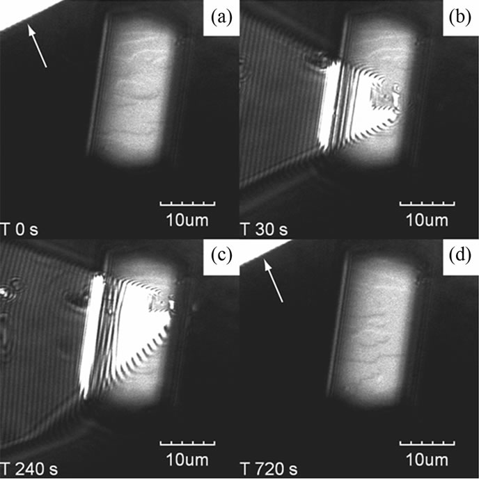
Figure 1. Snapshots of LCM-DIM images of HEW lysozyme crystal growth with an AFM cantilever tip. Two-dimensional nucleus steps grew on the {110} surface of HEW lysozyme in a supersaturated solution. The cantilever tip at the upper left is shown by arrows before (a) and after (d) AFM scanning. During the AFM observation (b) and (c), the cantilever was distorted because of image lag.
only when the AFM scanned (Figures 1(b) and (c)). This was because the reflected light prevented us from observing the weak contrast of steps by LCM-DIM. Figure 1(a) shows the two-dimensional (2D) nucleation growth on the {110} surface of the HEW lysozyme crystal. A comparison of Figures 1(a) and (d) shows that there is no difference in the step advancing before and after AFM scanning. If the cantilever had affected the step movements, the 2D step would have lost its shape. It is, therefore, confirmed that the dual images could be successfully observed without disturbing each other.
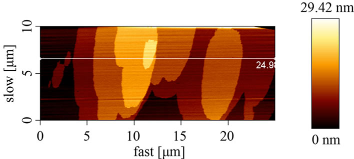
The corresponding AFM image of the LCM-DIM image (shown in Figure 1) and its height profile are shown in Figure 2. In order to reduce the image acquisition time, the scan region was set to be rectangular (25 μm × 10 μm). We observed the same, but not identical, shape of steps. This difference was caused by the growing steps during AFM scanning. From the AFM observation, the height of the steps was estimated to be about 5 nm.
Here we discuss the comparison between LCM-DIM imaging and AFM imaging and how to combine the two. LCM-DIM had the advantage over AFM in imaging time. In addition, LCM-DIM could observe almost the same height level with AFM. Therefore, presently, simultaneous LCM-DIM and AFM imaging seems to be worthless. However, in contrast to 2D imaging, one-dimensional (1D) imaging, i.e., the line scan of AFM, can enhance the value of this interactive observation. The acquisition time of the line scan is about several seconds. Furthermore, the line scan can quantify the step height, which is the weak point of LCM-DIM. On the other hand, LCM-DIM
 (a)
(a)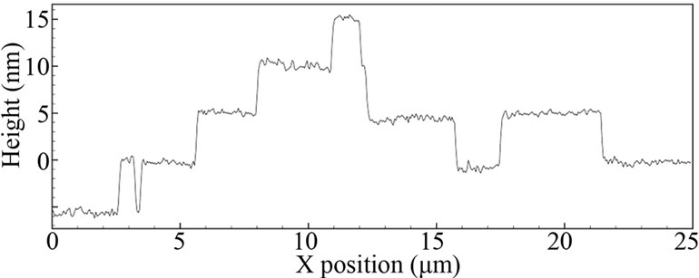 (b)
(b)
Figure 2. AFM image of the {110} surface (a), which is the same as that shown in Figure 1 and the height profile (b) indicated by the white line in Figure 2(a).
observations can also help the AFM line scan by locating the position. Therefore, LCM-DIM imaging with AFM line scan is one of the most productive application of this hybrid microscope.
Next, the in-situ observation of nano scratching was performed using an AFM cantilever tip that had a large spring constant. Figures 3(a)-(f) shows LCM-DIM images of the HEW lysozyme during approaching (Figure 3(a)), scanning (Figures 3(b) and (c)), and retracting (Figures 3(d)-(f)) tip. A hole and 2D nucleation site of different contrast were observed around the tip-approaching point, as shown Figure 3(a). The hole depth was about 1.5 μm, as shown in Figures 3(g). Figures 3(b)-(f) show
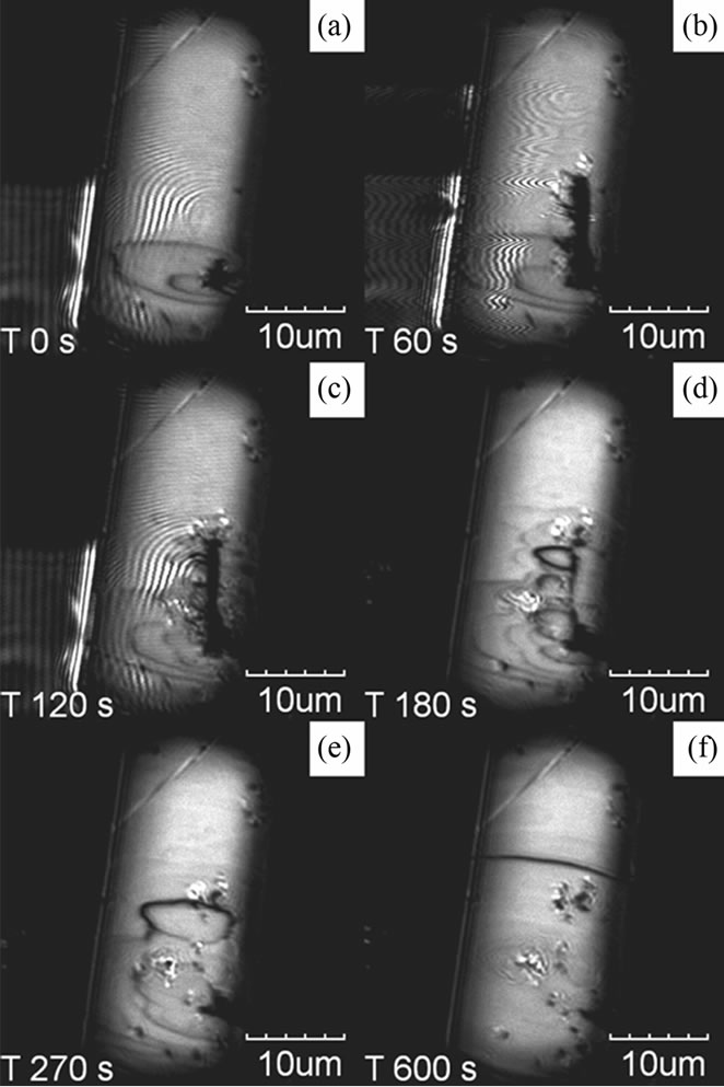

Figure 3. Snapshots of nano scratching using a hard cantilever tip (a)-(f) and the AFM profiles of the first scan (g). The time period of the images was 60 s (b), 120 s (c), 180 s (d), 270 s (e) and 600 s (f) after the LCM-DIM observation started (a). The AFM scan was repeated 40 times. After scanning, the cantilever stayed on the surface for 2 min (b) and (c) and moved away from the crystal. After scratching, the ditch was buried by the growing steps (c)-(f).
the time course of scratching and recovering of the surface. The scratching was performed by scanning the cantilever at a normal force in the intermittent mode. The scanning length was 10 μm and the tip scanned 40 times. Many steps were generated at the scratched line, and the line was covered with growth steps. Some debris remained on the surface even after the surface seemed to be almost flat (Figure 3(f)). Kuznetsov et al. reported the AFM observation of nucleation after scratching of the thaumatin crystal surface with an AFM cantilever at different supersaturations [20]. They described that molecules detached from the crystal recrystallized again on the substrate in the supersaturated solution. Our results correspond to the most supersaturated conditions of their experiments.
In order to estimate the minimum force for scratching the crystal surface, we estimated the extent of the force of the tip that affects surface morphology by using a hybrid microscope. Figure 4 shows typical images of the surface where the cantilever tip approached and then retracted. We first searched the flat area shown in Figure 4(a) to detect small changes. After retracting, a small spot was observed, as shown in Figure 4(c) when the force of the approach exceeded a certain value. After several tens of seconds, the spot disappeared, as shown in Figure 4(d). The boundary force was different between increasing and decreasing the force. The observation of the spot started from 1.3 μN when the force was increased, and ended at 0.5 μN when it was decreased. This
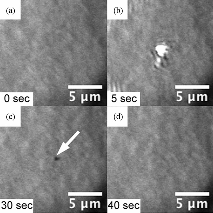
Figure 4. Time series images of the indentation by the AFM tip and its recovering. The images are taken every 5 s and the tip was approached for 20 - 30 s. They are typical images of (a) a flat surface before tip approaching; (b) the tip approaching on the surface; (c) a small hole on the surface after the tip retracted; and (d) the recovered flat surface.
is believed to happen because the measured forces had two meanings. One is the force when the tip dig the lysozyme crystal, and the other is the force when the lysozyme crystal attached on the AFM cantilever tip crashed.
4. Conclusion
We demonstrated the joint operation of AFM and LCMDIM for studying HEW lysozyme crystal surface processes in a supersaturated solution. The simultaneous AFM and LCM-DIM observation was performed using a soft cantilever. On the other hand, the in-situ observation of surface scratching and recovering was performed using a hard AFM cantilever tip. The in-situ observation of nano indentation, the minimum force required to knock a hole on the crystal surface was about 1.3 μN.
REFERENCES
- G. Binnig, C. F. Quate and Ch. Gerber, “Atomic Force Microscope,” Physical Review Letters, Vol. 56, No. 9, 1986, pp. 930-933. doi:10.1103/PhysRevLett.56.930
- R. J. Owen, C. D. Heyes, D. Knebel, C. Röcker and G. U. Nienhaus, “An Integrated Instrumental Setup for the Combination of Atomic Force Microscopy with Optical Spectroscopy,” Biopolymers, Vol. 82, No. 4, 2006, pp. 410-414. doi:10.1002/bip.20414
- K. Tsukamoto and P. Dold, “Interferometric Techniques for Investigating Growth and Dissolution of Crystals in Solutions,” In: A. Skowronski, J. J. DeYoreo and C. Wang, Eds., Perspectives on Inorganic, Organic, and Biological Crystal Growth: From Fundamentals to Applications, American Institute of Physics, College Park, 2007, pp. 329-341.
- G. Sazaki, T. Matsui, K. Tsukamoto, N. Usami, T. Ujihara, K. Fujiwara and K. Nakajima, “In Situ Observation of Elementary Growth Steps on the Surface of Protein Crystals by Laser Confocal Microscopy,” Journal of Crystal Growth, Vol. 262, No. 1-4, 2004, pp. 536-542. doi:10.1016/j.jcrysgro.2003.10.049
- A. E. S. Van Driessche, G. Sazaki, G. Dai, F. Otalora, J. A. Gavira, T. Matsui, I. Yoshizaki, K. Tsukamoto, and K. Nakajima, “Direct Observation of Adsorption Sites of Protein Impurities and Their Effects on Step Advancement of Protein Crystals,” Crystal Growth & Design, Vol. 9, No. 7, 2009, pp. 3062-3071. doi:10.1021/cg8006684
- A. E. S. Van Driessche, J. A. Gavira, L. D. Patino Lopez, and F. Otalora, “Precise Protein Solubility Determination by Laser Confocal Differential Interference Contrast Microscopy,” Journal of Crystal Growth, Vol. 311, No. 13, 2009, pp. 3479-3484. doi:10.1016/j.jcrysgro.2009.04.023
- S. Yanagiya and N. Goto, “Hybrid Observation of Crystal Growth using Laser Confocal Microscope with Atomic Force Microscope,” Journal of Crystal Growth, Vol. 312, No. 22, 2010, pp. 3356-3360. doi:10.1016/j.jcrysgro.2010.08.035
- S. Yanagiya and N. Goto, “Interference Phenomena Observed on an Atomic Force Microscope Cantilever by Laser Confocal Microscopy,” Japanese Journal of Applied Physics, Vol. 50, No. 4, 2011, pp. 08LB17-1-4. doi:10.1143/JJAP.50.08LB17
- Y. G. Kuznetsov, A. J. Malkin, A. Greenwood and A. McPherson, “Interferometric Studies of Growth-Kinetics and Surface-Morphology in Macromolecular Crystal-Growth— Canavalin, Thaumatin, and Turnip Yellow Mosaic-Virus,” Journal of Structural Biology, Vol. 114, No. 3, 1995, pp. 184-196. doi:10.1006/jsbi.1995.1018
- S. Miyashita, H. Komatsu, Y. Suzuki and T. Nakada, “Observation of the Concentration Distribution around a Growing Lysozyme Crystal,” Journal of Crystal Growth, Vol. 141, No. 3-4, 1994, pp. 419-424. doi:10.1016/0022-0248(94)90247-X
- K. Kurihara, S. Miyashita, G. Sazaki, T. Nakada, S. Durbin, H. Komatsu, T. Ohba and K. Ohki, “Incorporation of Impurity to a Tetragonal Lysozyme Crystal,” Journal of Crystal Growth, Vol. 196, No. 2-4, 1999 pp. 285-290. doi:10.1016/S0022-0248(98)00872-0
- S. D. Durbin and W. E. Carlson, “Lysozyme Crystal Growth Studied by Atomic Force Microscopy,” Journal of Crystal Growth, Vol. 122, No. 1-4, 1992, pp. 71-79. doi:10.1016/0022-0248(92)90228-B
- P. G. Vekilov and F. Rosenberger, “Dependence of Lysozyme Growth Kinetics on Step Sources and Impurities,” Journal of Crystal Growth, Vol. 158, No. 4, 1996, pp. 540-551. doi:10.1016/0022-0248(95)00398-3
- Y. G. Kuznetsov, A. J. Malkin, T. A. Land, J. J. DeYoreo, A. P. Barba, J. Konnert and A. McPherson, “Molecular Resolution Imaging of Macromolecular Crystals by Atomic Force Microscopy,” Biophysical Journal, Vol. 72, No. 5, No. 5, 1997, pp. 2357-2364. doi:10.1016/S0006-3495(97)78880-5
- T. Nakada, G. Sazaki, S. Miyashita, S. D. Durbin and H. Komatsu, “Direct AFM Observations of Impurity Effects on a Lysozyme Crystal,” Journal of Crystal Growth, Vol. 196, No. 2-4, 1999, pp. 503-510. doi:10.1016/S0022-0248(98)00875-6
- L. Rong, T. Yamane and N. Niimura, “Measurement and Control of the Crystal Growth Rate of Tetragonal Hen Egg-White Lysozyme Imaged with an Atomic Force Microscope,” Journal of Crystal Growth, Vol. 217, No. 1-2, 2000, pp. 161-169. doi:10.1016/S0022-0248(00)00380-8
- H. Hondoh, G. Sazaki, S. Miyashita, S. D. Durbin, K. Nakajima and Y. Matsuura, “Macrobond Analysis of the Macroand Micromorphology of Monoclinic Lysozyme Crystal,” Crystal Growth & Design, Vol. 1, No. 4, 2001, pp. 327-332. doi:10.1021/cg015506n
- H. Komatsu and S. Miyashita, “Comparison of Atomic Force Microscopy and Nanoscale Optical Microscopy for Measuring Step Heights,” Japanese Journal of Applied Physics, Vol. 32, 1993, pp. 1478-1479. doi:10.1143/JJAP.32.1478
- A. E. S. Van Driessche, F. Otalora, G. Sazaki, M. Sleutel, K. Tsukamoto and J. A. Gavira, “Comparison of Different Experimental Techniques for the Measurement of Crystal Growth Kinetics,” Crystal Growth & Design, Vol. 8, No. 12, 2008, pp. 4316-4323. doi:10.1021/cg800782r
- Y. G. Kuznetsov, A. J. Malkin and A. McPherson, “AFM Studies of the Nucleation and Growth Mechanisms of Macromolecular Ccrystals,” Journal of Crystal Growth, Vol. 196, No. 2-4, 1999, pp. 489-502. doi:10.1016/S0022-0248(98)00856-2
NOTES
*Corresponding author.