Journal of Surface Engineered Materials and Advanced Technology
Vol.1 No.3(2011), Article ID:7986,5 pages DOI:10.4236/jsemat.2011.13016
Electrochemical Characterization of Plasma Sprayed Alumina Coatings
![]()
1CSIRO Division of Materials Science and Engineering, Clayton South, Victoria, Australia; 2Joining and Welding Research Institute, Osaka University, Osaka, Japan.
Email: *magdi.hanna@csiro.au
Received June 27th, 2011; revised July 31st, 2011; accepted August 12th, 2011.
Keywords: Plasma Spraying, Alumina Coating, Mild Steel, Corrosion, Polarization, EIS
ABSTRACT
Open circuit potential (OCP), potentiodynamic polarization, and electrochemical impedance spectroscopy (EIS) were employed to characterize the corrosion behavior of plasma-sprayed alumina-coated mild steel in 3.5 wt% NaCl solution. Alumina-coated steel showed higher OCP and lower corrosion current (icorr.) compared with the steel substrate. However, localized corrosion probably occurs at the coat/steel interface when immersed in the corrosive media. The reason for that is the penetration of corrosive solution into the steel surface through the pores of accumulated alumina layers. The corrosion products (mainly iron oxides) accumulate inside the pores and on the coating surface. The presence of iron oxide slightly improved the corrosion resistance.
1. Introduction
Ceramic coatings generated by plasma spraying have been extensively used as anti-corrosion, abrasion and wear resistant layers for metallic structural components [1-3]. Such coatings are used by many industries such as automotive, mining and aerospace to protect internal components from corrosion and friction under severe condition such as temperature and corrosive materials. Pla-sma-sprayed (PS) alumina and alumina/titania ceramic coatings have been studied extensively because they are electrical and thermal insulators and improve the corrosion, wear, and erosion resistance of steel that has been configured [4-7].
The disadvantages associated with plasma-spraying of ceramic coatings are the rapid solidification of the flight particles and thermal stresses which propagate microcracks within the coatings and limit the coating thickness to a few hundred microns. Moreover, the pores initiated from unmelted and semi-melted particles cause defects in the thermal spray coatings. In addition, exposed metallic oxide powders can undergo phase changes, as in the case of the phase transition of plasma-sprayed Al2O3 to Al2O3 [8,9] due to the difficulty of nucleating stable -phase [10] under the rapid solidification rate associated with the plasma spraying process.
Plasma sprayed alumina coatings are corrosion-resistant; however, the porous structure of PS alumina coatings enables localized corrosion by penetration to the surface/coating interface of corrosive agents. In the case of an alumina/mild steel system, localized corrosion occurs and iron oxide is released by immersion in 3.5 wt% NaCl solution. The corrosion products at the interface could cause a failure of the whole coatings due to the decrease in adhesive strength.
In mining industries, PS alumina coatings provide excellent protection for steel tools and components against wear, abrasive and corrosion. However, the coatings defects such as cracks and pores usually cause localized corrosion in wet environment.
Pore sealing is one method to improve the corrosion resistance of the coatings. This can be performed by applying inhibitors or a phosphate conversion treatment. Heung et al. [11] found that the electrochemical impedance spectroscopy (EIS) is advanced technique to investigate the thermal barrier coatings contain metallic and ceramic layers.
In this work, the corrosion behavior of PS alumina coatings on mild steel was evaluated by means of OCP, polarization and EIS. The work will focus on the problem of corrosion in porous PS ceramic coatings and investigate it with electrochemical.
2. Experimental Method
2.1. Materials
Mild steel samples (50 × 50 × 3 mm) were grit-blasted on one side to clean and roughen the surface and followed by ultrasonic cleaning using acetone to remove grease and dust. Alumina coating was applied on the prepared mild steel surface by plasma spray system (Bay-tate-Coaken Techno-Osaka-Japan) in air. The spray parameters are listed in Table 1. Argon was employed as the working gas as well as a carrier for the alumina particles into the plasma flame. Under plasma power of 25 kW, the alumina was sprayed continuously by moving the plasma gun, attached to a programmable robot, in front of the substrate. For all coatings, the spray distance was 100 mm.
2.2. Characterization
Cross-sectioned alumina coated steel was mounted in resin and polished with diamond paste (15, 9, 3, 1 m). Scanning electron microscopy (SEM) imaging and mapping, and energy-dispersive spectroscopy (EDS) was carried out using a Philips XL30 FESEM with a LinkISIS X-ray analysis system (Oxford Instruments). EDS was carried out with a beam current of 5 kV. All samples were mounted using conductive carbon tape.
A JEOL JDX-3530 M X-ray diffractometer system was employed to analyze the phase structure of both the alumina feedstock and coatings. In the phase analysis, the radiation source was CuK; the operating voltage was 40 kV and current 40 mA.
A three-electrode corrosion cell, interfaced with a potentiostat (model HSV-100, Hokuto Denko Co., Japan), measured Tafel polarization plots. Electrochemical measurements were conducted at 25˚C. Cathodic and anodic polarizations were recorded from −1.5 to −0.2 V with a sweep rate of 0.5 mV/s in a 3.5 wt% NaCl solution. The electrochemical cell consisted of Calomel electrode (Hg/ Hg2Cl2) as the reference electrode, a Ti mesh (10 × 20 mm2) as counter electrode, with the samples mounted in the substrate holder as working electrode. The area of the sample exposed to the electrolyte was 3.14 cm2. Electrolyte solutions were prepared with analytical-grade NaCl and distilled water. The polarization curves were measured immediately after recording the open circuit potential (OCP) of the samples for 50 min in 3.5 wt% NaCl solution.
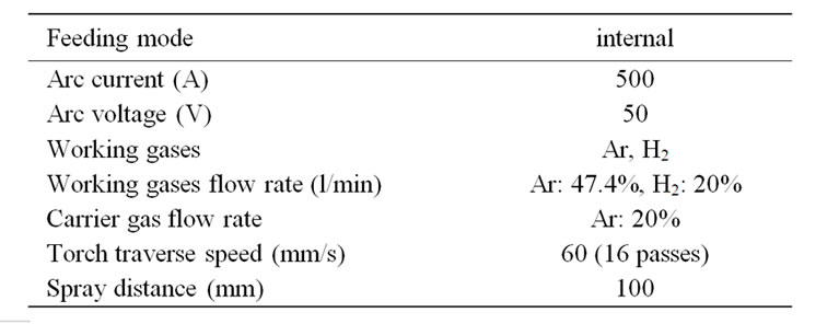
Table 1. Spray parameters used for PS alumina coatings.
3. Results and Discussion
3.1. Microstructure and Phase Structure
The PS alumina coating of thickness 500 - 600 m has lamella structure (Figure 1) formed by accumulation of molten alumina particles. The microstructure reveals the different coating defects such as pores, micro-cracks, and non-/semi-molten particles (white angular dots). The coating is well-adhered to the steel surface as there are no cracks observed at the interface.
From X-ray diffraction analysis (Figure 2), the starting alumina powder is mainly comprised of -alumina, while the main phase in the PS alumina coatings are due to -alumina, which is formed from -alumina phase transition at high plasma flame temperature.
3.2. Electrochemical Measurements
3.2.1. Open Circuit Potential
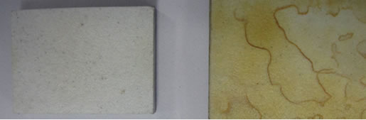
Figure 3 show the alumina-coated steel before and after corrosion test. The yellow color may be revealed to the corrosion products at the steel/coating interface that accumulated in the pores.
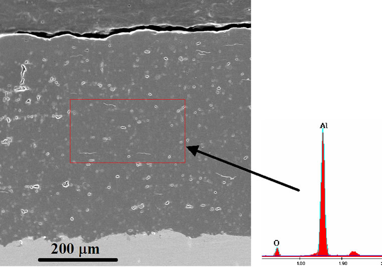
Figure 1. SEM and EDS of PS alumina coating.
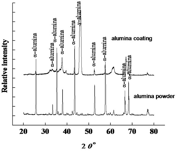
Figure 2. XRD patterns of alumina feedstock and coating.
 (a) (b)
Figure 3. Photos for Al2O3 surface (a) before and (b) after corrosion.
Figure 4 shows the open circuit potential (OCP) curves of alumina coating and mild steel in 3.5 wt% NaCl solution at room temperature. Alumina coated steel exhibited a more positive OCP (–0.49 and –0.51 V) compared to mild steel (–0.61 V). The OCP of aluminacoated steel after corrosion testing was slightly shifted to more positive value (–0.49 V) due to the iron oxide formation inside the pores. Also the potential was in steadystate along the time of experiment. This confirms the higher corrosion resistance of alumina-coated steel compared to steel.
3.2.2. Tafel Polarization Curves
Tafel polarization curves of alumina-coated steel and mild steel are shown in Figure 5. The polarization curves of alumina showed a shift of corrosion potential to more positive value (–0.61 and –0.64 V) compared with mild steel (–0.92 V). The corrosion current (icorr) was shifted to lower values in case of the alumina-coated steel, indicating a higher corrosion resistance. The alumina-coated steel exhibited slightly higher corrosion resistance when re-measured the same sample, mainly due to the accumulation of corrosion products particles, which may be iron oxide particles, inside the pores. The corrosion products particles blocked and sealed the pores from further penetration of corrosive solution. After corrosion test, the color of alumina coating was changed from white to rusty, due to the formation of oxides inside the pores and onto the alumina surface (Figure 3).
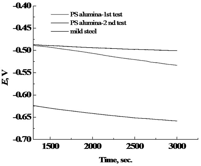
Figure 4. Open circuit curves for Al2O3 and mild steel.
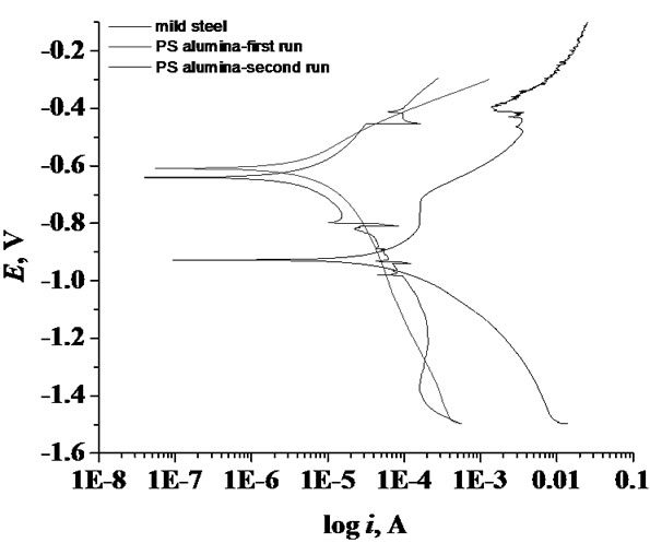
Figure 5. Tafel polarization curves for Al2O3 and mild steel.
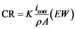
Table 2 summarizes the OCP, Ecorr and icorr of coated steel and steel samples in 3.5% NaCl. The corrosion rate (CR) is calculated from the following equation [12] ASTM Standard G 102):
 (1)
(1)
where: K (3272 mm/(amp-cm-year) is a constant for converting units; is density of corrode metal (steel: 7.85 g·cm–3); EW (Fe: 27.93 g/equivalent) is the element equivalent weight and A is the sample surface area (3.14 cm2).
By applying this equation on pure steel and alumina coated steel, the alumina coating was found to reduce the steel corrosion rate from 3.11 mm/year to 0.243 and 0.2 mm/year when applied alumina.
3.2.3. Electrochemical Impedance Spectroscopy
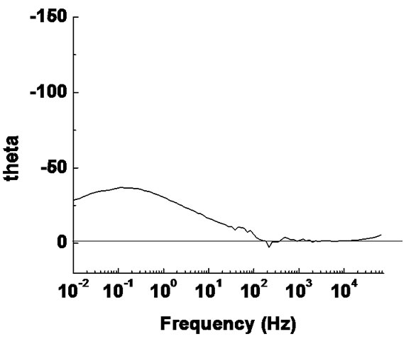
Impedance measurements of PS alumina were carried out at OCP conditions in 3.5% NaCl solution at room temperature. The impedance spectra obtained, are shown as complex impedance (Nyquist diagram) and Bode plots in Figure 6.
In the Nyquist diagram, the imaginary part of the impedance (Z") against real part (Z') is recognized in the form of a semicircle. The equivalent circuit that fits the impedance data consists of a resistor connected in series to a parallel connected resistor and CPE unit as shown in the equivalent circuit diagram in Figure 7.
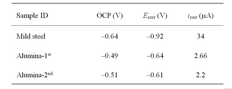
Table 2 measured and calculated values of OCP, Ecorr and icorr of mild steel and coated alumina steel.
 (a)
(a)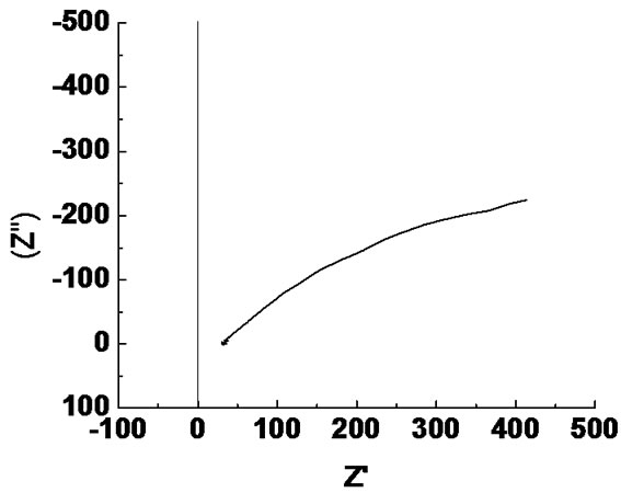 (b)
(b)
Figure 6. (a) Bode plot and (b) Nyquist plot for Al2O3 coating on mild steel.
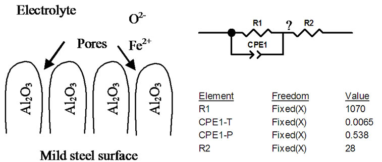
Figure 7. Physical and equivalent circuit diagrams for Al2O3 coating on mild steel.
The impedance magnitude |z| (the ratio of the voltage difference amplitude to the current amplitude) increases as the frequency decreases. Over the frequency range of Max to 160 Hz the phase angle was nearly zero and the alumina layer behaves as pure resistor (q = 0˚). For frequencies less than 160, the phase started to decrease from 0 towards –34.6˚ at 0.01 Hz.
In the equivalent circuit model, R1 represent the pores resistance with resistance equivalent to 1 KΩ. It is equivalent to the solution resistance inside the pores. R2 is the electrolyte solution resistance. CPE1 component is equivalent to double layer at the pore base which is mainly formed from negatively (electrons) and positively (Fe++) charges distribution inside the pores. The high electrical resistivity of alumina (1014 Ω·cm) was not represented in the model as it was considered as open circuit. The electrochemical redox reactions associated with iron corrosion are:
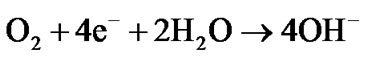 (cathodic reaction)
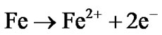 (anodic reaction)
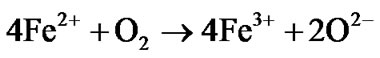 (Redox reaction)
The corrosion current flow in and out of the coating pores and cracks which are full with electrolyte and avoid the alumina due to its high resistivity. The low impedance value (1070 Ω) of (R1) is for steel surface treated with porous alumina layer. The results reflect the low in corrosion resistance of PS alumina mainly due to the coating porosity.
4. Conclusions
1) The Tafel polarization curves demonstrated an improvement in corrosion resistance of mild steel by applying PS alumina coating.
2) Localized corrosion is likely to happen at the interface due to the porous structure of alumina layer.
3) The equivalent circuit showed the low impedance value of alumina coated mild steel due to the porous structure of alumina layer.
4) The corrosion current is only flowing in and out of the coating pores and cracks avoiding the alumina barrier due to its high resistivity.
5. Acknowledgements
The authors acknowledge the financial support from CSIRO, CMSE-Clayton.
REFERENCES
- M. F. Morks, Y. Gao, N. F. Fahim and F. U. Yingqing, “Microstructure and Hardness Properties of Cermet Coating Sprayed by Low Power Plasma,” Materials Letters, Vol. 60, No. 1, 2006, pp. 1049-1053. doi:10.1016/j.matlet.2005.10.073
- M. F. Morks, Y. Gao, N. F. Fahim, F. U. Yingqing and M. A. Shoeib, “Influence of Binder Materials on the Properties of Low Power Plasma Sprayed Cermet Coatings,” Surface and Coating Technology, Vol. 199, No. 1, 2005, pp. 66-71. doi:10.1016/j.surfcoat.2005.02.159
- M. F. Morks, A. Ibrahim and M. Shoeib, “Comparative study of Nanostructured and Conventional WC-Co Coatings,” Proceedings of The International Thermal Spray Conference, Osaka, May 2004.
- B. Pavitra, P. Nitin Padture and V. Alexandre, “Improved Interfacial Mechanical Properties of Al2O3 – 13 wt% TiO2 Plasma-Sprayed Coatings Derived from Nanocrystalline Powders,” Acta Materialia, Vol. 51, No. 10, 2003, pp. 2959-2970. doi:10.1016/S1359-6454(03)00109-5
- V. P. Singh, A. Sil and R. Jayaganthan, “A Study on Sliding and Erosive Wear Behaviour of Atmospheric Plasma Sprayed Conventional and Nanostructured Alumina Coatings,” Materials and Design, Vol. 32, No. 2, 2011, pp. 584-591. doi:10.1016/j.matdes.2010.08.019
- O. Tingaud, P. Bertrand and G. Bertrand, “Microstructure and Tribological Behavior of Suspension Plasma Sprayed Al2O3 and Al2O3–YSZ Composite Coatings,” Surface & Coating Technology, Vol. 205, No. 4, 2010, pp. 1004- 1008. doi:10.1016/j.surfcoat.2010.06.003
- C.-J. Li, G.-J. Yang and A. Ohmori, “Relationship between Particle Erosion and Lamellar Microstructure for Plasma-Sprayed Alumina Coatings,” Wear, Vol. 260, No. 2, 2006, pp. 1166-1172. doi:10.1016/0272-8842(81)90013-4
- M. Vardelle and J. L. Besson, “Alumina Obtained by Arc Plasma Spraying: A Study of the Optimization of Spraying Conditions,” Ceramics International, Vol. 7, No. 2, 1981, pp. 48-54.
- R. McPherson, “Formation of Metastable Phases in Flame and Plasma-Preapared Alumina,” Journal of Material Science, Vol. 8, No. 6, 1973, pp. 851-858.
- R. McPherson, “On the Formation of Thermally Sprayed Alumina Coatings,” Journal of Material Science, Vol. 15, No. 31, 1980, pp. 41-49.
- R. Heung, X. Wang and P. Xiao, “Characterisation of PSZ/Al2O3 Composite Coatings Using Electrochemical Impedance Spectroscopy,” Electrochimica Acta, Vol. 51, No. 8-9, 2006, pp. 1789-1796. doi:10.1016/j.electacta.2005.02.097
- ASTM Standard G 102.