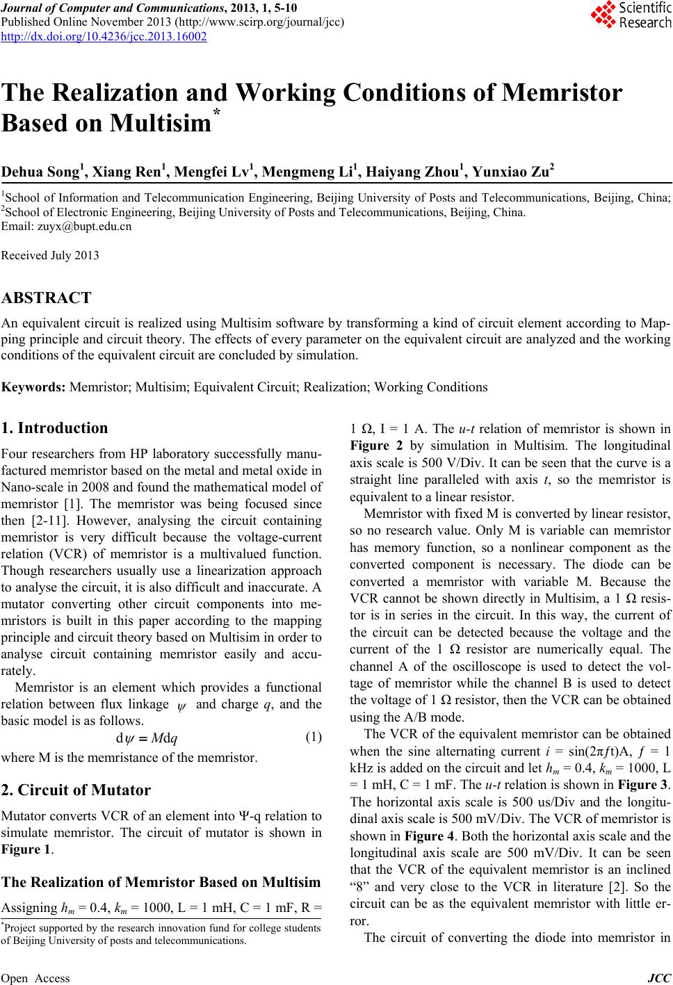
The Realization and Working Conditions of Memristor Based on Multisim
Open Access JCC
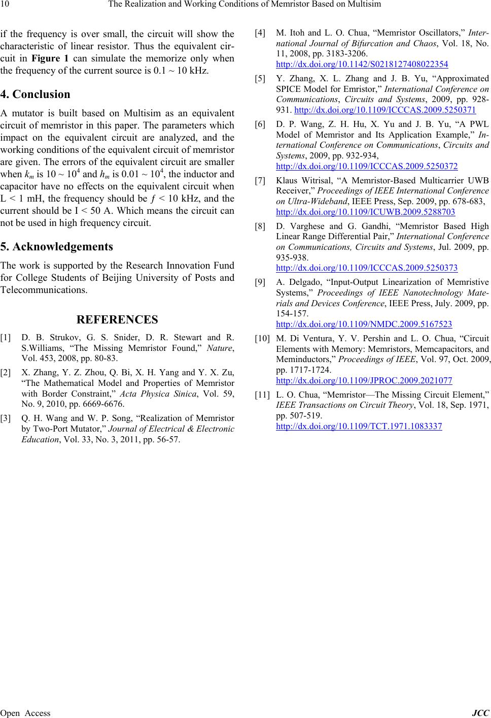
Figure 6. The u-t relation for different km.
approaches to a straight line and closes to i axis when km
increasing, while the shape of the u-t curve does not
change but the voltage peak decreasing. Assigning km =
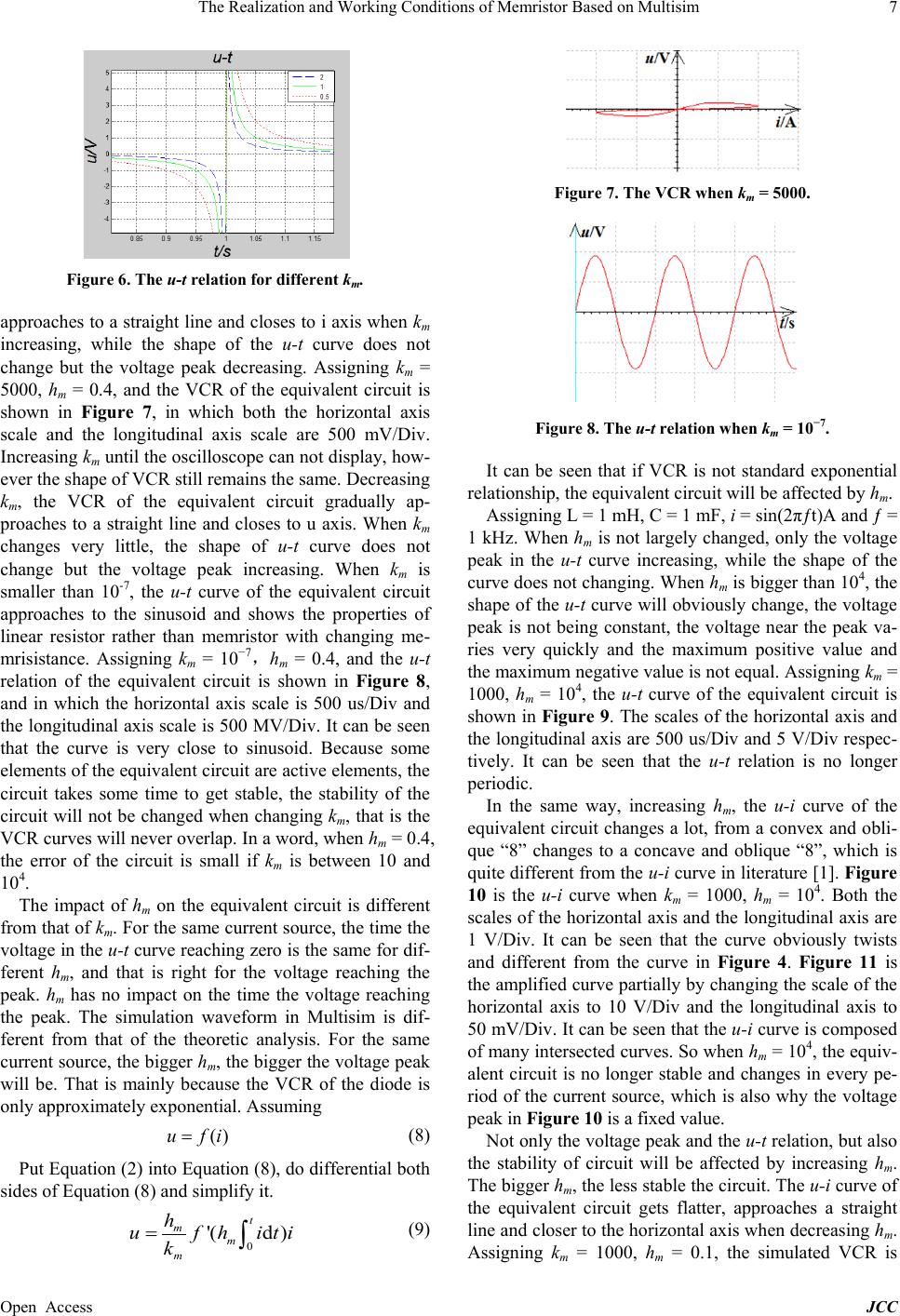
5000, hm = 0.4, and the VCR of the equivalent circuit is
shown in Figure 7, in which both the horizontal axis
scale and the longitudinal axis scale are 500 mV/Div.
Increasing km until the oscilloscope can not display, how-
ever the shape of VCR still remains the same. Decreasing
km, the VCR of the equivalent circuit gradually ap-
proaches to a straight line and closes to u axis. When km
changes very little, the shape of u-t curve does not
change but the voltage peak increasing. When km is
smaller than 10-7, the u-t curve of the equivalent circuit
approaches to the sinusoid and shows the properties of
linear resistor rather than memristor with changing me-
mrisistance. Assigning km = 10−7,hm = 0.4, and the u-t
relation of the equivalent circuit is shown in Figure 8,
and in which the horizontal axis scale is 500 us/Div and
the longitudinal axis scale is 500 MV/D iv. It can be seen
that the curve is very close to sinusoid. Because some
elements of the equivalent circuit are active elements, the
circuit takes some time to get stable, the stability of the
circuit will not be changed when changing km, that is the
VCR curves will never overlap. In a word, when hm = 0.4,
the error of the circuit is small if km is between 10 and
104.
The impact of hm on the equivalent circuit is different
from that of km. For the same current source, the time the
voltage in the u-t curve reaching zero is the same for dif-
ferent hm, and that is right for the voltage reaching the
peak. hm has no impact on the time the voltage reaching
the peak. The simulation waveform in Multisim is dif-
ferent from that of the theoretic analysis. For the same
current source, the bigger hm, the bigger the voltage peak
will be. That is mainly because the VCR of the diode is
only approximately exponential. Assuming
(8)
Put Equation (2) into Equation (8), do differential both
sides of Equation (8) and simplify it.
(9)
Figure 7. The VCR when km = 5000.
Figure 8. The u-t relation when km = 10−7.
It can be seen that if VCR is not standard exponential
relationship, the equivalent circuit will be affected by hm.
Assigning L = 1 mH, C = 1 mF, i = sin(2πƒt)A and ƒ =
1 kHz. When hm is not largely changed, only the voltage
peak in the u-t curve increasing, while the shape of the
curve does not changing. When hm is bigger than 104, the
shape of the u-t curve will obviously change, the voltage
peak is not being constant, the voltage near the peak va-
ries very quickly and the maximum positive value and
the maximum negative value is not equal. Assigning km =
1000, hm = 104, the u-t curve of the equivalent circuit is
shown in Figure 9. The scales of the horizontal axis and
the longitudinal axis are 500 us/Div and 5 V/Div respec-
tively. It can be seen that the u-t relation is no longer
periodic.
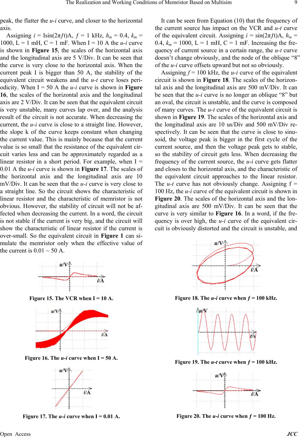
In the same way, increasing hm, the u-i curve of the
equivalent circuit changes a lot, from a convex and obli-
que “8” changes to a concave and oblique “8”, which is
quite different from the u-i curve in literature [1]. Figure
10 is the u-i curve when km = 1000, hm = 104. Both the
scales of the horizontal axis and the longitudinal axis are
1 V/Div. It can be seen that the curve obviously twists
and different from the curve in Figure 4. Figure 11 is
the amplified curve partially by changing the scale of the
horizontal axis to 10 V/Div and the longitudinal axis to
50 mV/Div. It can b e seen that the u-i curve is composed
of many intersected curves. So when hm = 104, the equiv-
alent circuit is no longer stable and changes in every pe-
riod of the current source, which is also why the voltage
peak in Figure 10 is a fixed value.
Not only the voltage peak and the u-t relation, but also
the stability of circuit will be affected by increasing hm.
The bigger hm, the less stable the circuit. The u-i curve of
the equivalent circuit gets flatter, approaches a straight
line and closer to the horizontal axis when decreasing hm.
Assigning km = 1000, hm = 0.1, the simulated VCR is