Journal of Computer and Communications, 2013, 1, 1-4
Published Online November 2013 (http://www.scirp.org/journal/jcc)
http://dx.doi.org/10.4236/jcc.2013.16001
Open Access JCC
1
Comput er Pr o gr a m C alcu lation for Di s t or ti on of
Wide-Band Track and Hold Amplifier
Hailang Liang1,2, Jin He1,2, Xiaoan Zhu2,3, Xiaomeng He2, Cheng Wang2,3, Lin He2, Gui Liu2,
Qingxing He4, Caixia Du4
1Tera-Scale Research Center, Institute of Microelectronics, School of Electronic Engineering and Computer Science, Peking Univer-
sity, Beijing 100871, China; 2Peking University Shenzhen SOC Key Laboratory, PKU-HKUST Shenzhen-Hong Kong Institution,
Shenzhen 518057, China; 3Dong Guan Xin Cheng Electronic Technology Ltd. Co., High-Tech Industrial Development Zone, Song-
shanhu Lake, Dongguan, China; 4Shenzhen Huayue Terascale Chip Ltd. Co., Shenzhen 518045, China
Email: frankhe@pku.edu.cn
Received June 2013
ABSTRACT
Tow different computer calculation methods for distortion of the wid e-band diode bridge track and hold amplifier (THA)
are presented based on a high frequency Schottky diode model. One of the computer programs calculates the distortion
of weekly nonlinear THA based on the KCL and the nonlinear-current method. The other calculates the weekly nonlin-
ear distortion by using a Volterra series method and a nodal formulation. Comparative calculation results for the diode
bridge THA have shown good agreement with these two computer program calculation methods, whereas the overall
computational efficiency of the nonlinear-current method is better than that of the nodal formulation method in a special
evaluation.
Keywords: Track and Hold Amplifier; Broadband Amplifiers; High-Speed Integrated Circuits; Schottky Diode
Frequency Converters; Harmonic Distortion; Volterra Analysis; Compute r Pro gram; Nonlinear-Current
Method
1. Introduction
A diode bridge architecture THA prior to the analog to
digital converters are used to implement low-cost ultra
high speed transceivers. Distortion is one of the impor-
tant factors that limit the dynamic range of THA [1]. It is
crucial to predict and calculate the distortion in the
weakly nonlinear circuit by computer program cal-
culation or simulation. Several methods used to resolve
the distortion issues are shown in [2-6]. Two computer
programs based on these methods are implemented to
evaluate the distortion of THA with an improved proce-
dure in terms of the Volterra series.
In this paper, two computer program are used to cal-
culate the weakly nonlin ear distortion of the diode bridge
switch THA based on the high frequency Schottky diode
model in terms of a Volterra-series analysis. Section 2
describes a diode bridge THA for ultra high speed appli-
cation. In Section 3, the high speed diode model,
assumptions and distortion analysis are presented. The
computer program description is proposed in Section 4.
Section 5 shows the program calculation results and then
follows by concl usion.
2. A Diode Bridge THA
Consider a diode bridge THA shown in Figure 1, which
is directly derived from Fig ure 2 in [7], this circuit con-
sists of a high-speed Schottky diode bridge (
1
D
to 4
D)
used as a switch between the input and output, a hold
Figure 1. A diode bridge track and hold amplifier [ 7].
Computer Program Calculation for Distortion of Wide-Band Track and Hold Amplifier
Open Access JCC
2
Figure 2. Program flow chart for calculating the distortion
[4,10].
capacitor
H
C
to maintain the sampling voltage, a diffe-
rential pair (
1
Q
and
2
Q
) to turn on/off the diode bridge
switch, two load inductors used to extend bandwidth, two
load resistors, a bootstrap buffer, a output buffer and a
current tail. This THA with diode bridge configuration is
suitable for wideband and high speed application [7].
3. Model, Assumptions and Distortion
Analysis
As shown in [8]. A simplified equivalent circuit for the
diode bridge THA in track mode is illustrated in Figure
3(a).
The first order Volterra kernel
)(
11
ω
jH
is given by
the following Equation (1) [1].
K
d
H
K
d
Cj
r
Cj
Cj
r
jH
11
1
11
1
1
=)(
ωω
ω
ω
++
+
(1)
The second order and the third Volterra kernel
),(
212
ωω
jjH
and
are shown in
Equation (2) and Equation (3) respectively. Equation (2)
and Equation (3) imply that if
1=)(
11
ω
jH
, the Vol-
terra kernels
),(
212
ωω
jjH
and
tend to zero.
)(
1
))((1
2
=),(
21
2
11
2
212
ωω
ω
ωω
jjC
rV
I
jH
V
I
jjH
K
dt
d
t
d
+++−
−−
(2)
21211
2
31 23
123
23
11111 1
3
123
(,)(() 1)
( ,,)=1()
(13()3() ())
61()
d
t
dK
td
d
t
dK
td
IHj jHj
V
Hj jjICj
Vr
IHjH jHj
VICj
Vr
ωω ω
ωωω
ωωω
ω ωω
ωωω
−−+ +
+− +−
+
−−+ +
(3)
The third-order harmonic distortion HD3 is the ratio of
the amplitude of the third-order harmonic to the ampli-
tude of the fundamental harmonic. With the Volterra co-
efficients,
3
HD
is defined as followings [1,9].
(a) (b)
Figure 3. A simplified equi val ent c irc uit for the di ode br idge
THA.
Computer Program Calculation for Distortion of Wide-Band Track and Hold Amplifier
Open Access JCC
3
2
11
3213
3
|)(|
|),,(|
4
1
=
in
V
jH
jjjH
HD
ω
ωωω
(4)
The third-order intermodulation distortion which is the
ratio of third-order kernel to the first-order kernel can be
expressed as [1].
2
3
11
3213
3
|)(|
|),,(|
4
3
=
in
V
H
H
IM
ω
ωωω
(5)
In term of Volterra analysis, one can choose the appro-
priate values for the bias current and the hold capacitor,
H
C
, to yield a suitable
3
IM
performance [1].
4. Computer Progr am D es crip tio n
(1) Nonlinear-current method:
The KCL and the nonlinear-current method are used in
this program. The detailed description of the nonlinear-
current method was proposed in [5,6], [4] and [10]. In
this approach the small-signal I/V characteristic for a
simple voltage-controlled conductance is expressed as
[10]:
...=
5
5
4
4
3
3
2
21
+++++ vgvgvgvgvgi
(6)
where the first-order voltage
)(tv
is
)(
2
1
=)(
,
=
tjexpvtv
qqs
Q
Qq
ω
(7)
the second-order curre nt [4 ,10] is
2
221
21, 1,
121 2
==
12
()= ()
[ ()]
4
QQ
qqq q
q QqQ
i tgvt
gvvexp jt
ωω
−−
++
∑∑
(8)
This program is implemented in Python in terms of the
nonlinear-current method and KCL [4,10]. The linear
resistors, diodes, capacitors, inductors, controlled sources,
transmission lines and the nonlinear resistors, diodes,
capacitors, and controlled sources are used in this pro-
gram for calculating the distortio n of Volterra series. The
flow chart for the program is illustrated in Fig ure 2,
where the basic algorithm used in this paper is depicted
in [4,10].
The program first initializes the environmental vari-
ables, which includes setting up the values of the re-
sistors, the capacitors, the diodes, the inductors, the
VCCS etc. and replacing every non-linearity with its
linearized equivalence.
Then the program begins to calculate the first order
voltage with linearized equivalence [4]. The output data
are saved and then the second and the third order currents
and voltages are computed, the calculation of these
higher order currents and voltage depends on those of the
lower order ones that have been saved. As shown in the
flow chart, the related currents and voltages are solved
for each order and the desired corresponding responses
are derived from the Volterra series.
(2) Volte r r a series and nodal formulation method:
The flow chart of this method is shown in Figure 4.
More detailed description of this method is depicted in
[11]. To compare with the results from those of non-
linear-current method, the program has been rewritten in
Python languag e .
5. Calculation Results
Figure 5 illustrates the IIP3 versus input frequency re-
sults of both nonlinear-current method and nodal for-
mulation method, which indicates that these two results
have a good agreement in the range of the input fre-
quency.
The results of the HD3 versus input frequency for both
nonlinear-current method and nodal formulation method
Figure 4. Program flow chart for the computation of vol-
terra kernels [2].
Computer Program Calculation for Distortion of Wide-Band Track and Hold Amplifier
Open Access JCC
4
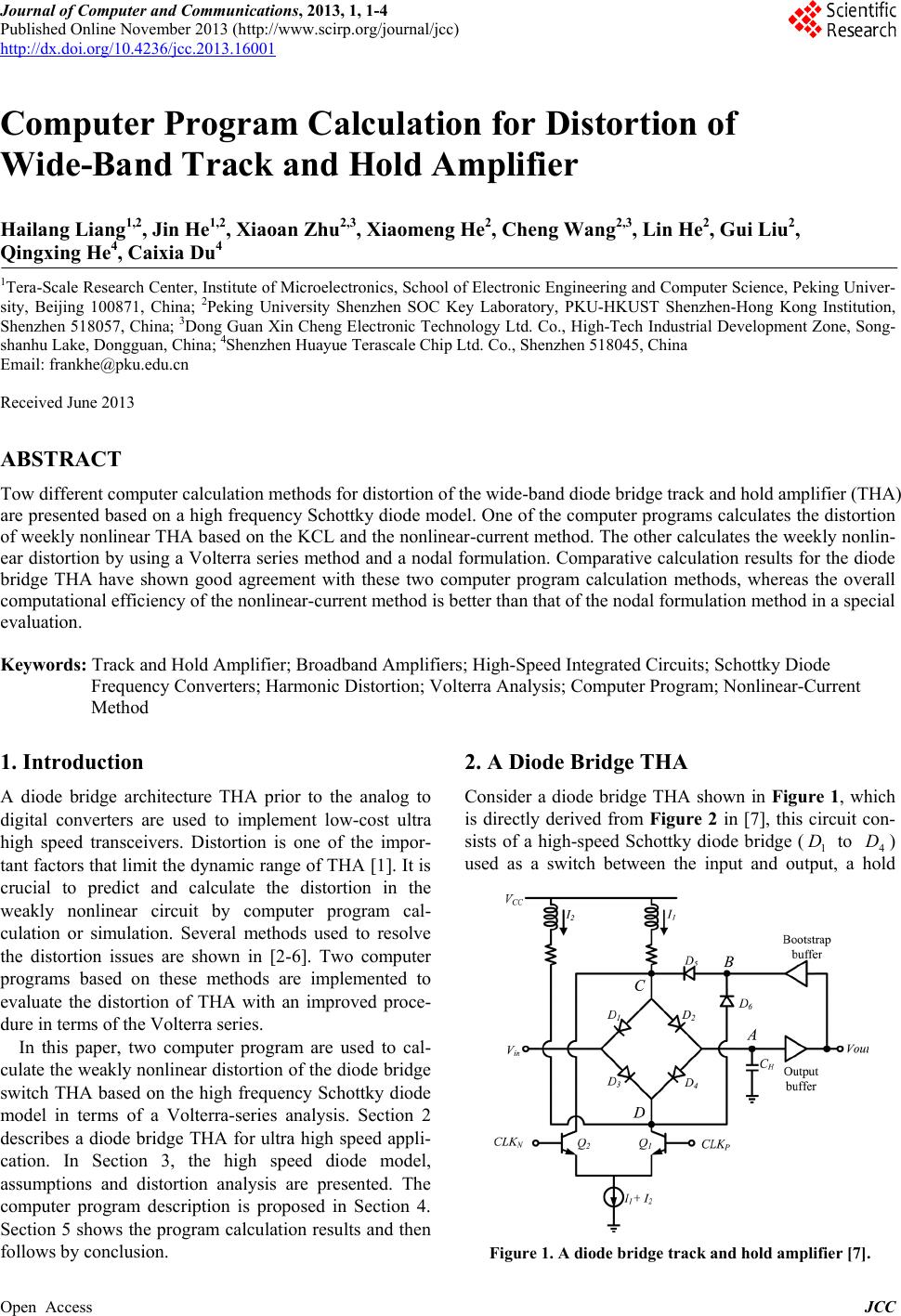
Figure 5. Comparison of third-order inter cept point.
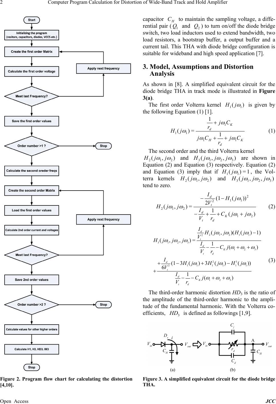
Figure 6. HD3 characteristics of diode bridge THA.
are illustrated in Figure 6, it shows that they are also
similar and have the agreement between them.
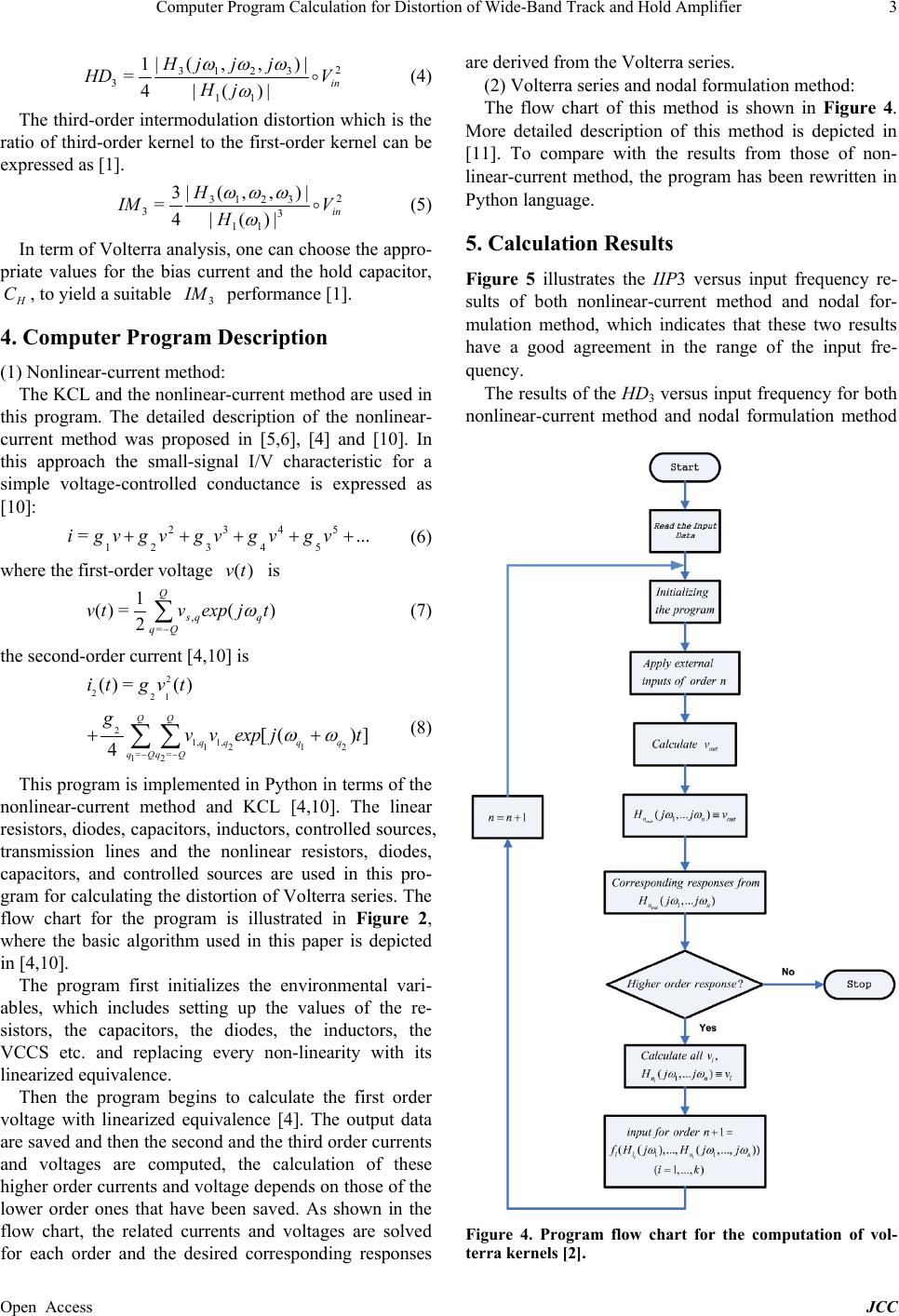
At some special test condition, the calculation time
results of both nonlinear-current method and nodal for-
mulation method are illustrated in Table 1. Obviously,
the calculation times of the nonlinear-current method is
much less than those of nodal formulation method with
the specified input frequency.
6. Conclusion
Nonlinear-current method and nodal formulation method
for distortion calculation of the diode bridge configura-
tion THA are presented by using a simplified high-speed
diode model. Comparative results show that the cal-
culation results derived by the nonlinear-current method
is consistent with thos e of the nodal formulation method,
whereas the overall calculation time of the nonlinear-
current method has been improved.
7. Acknowledgements
This work is supported by the Industry Education and
Table 1. Summary of calculation time.
Frequency (GHz) 1 3 5
Nonlinear-current method (Sec) 12.78 36.42 42.75
Nodal formulation method (Sec) 25.17 72.49 87.73
Research Foundation of PKU-HKUST Shenzhen-Hong-
kong Institution (sgxcyhzjj201204), by the Guangdong
Natural Science Foundation (S2011040001822) and the
Fundamental Research Project of Shenzhen Science and
Technology Foundation JCYC20120618163025041 . This
work is also supported by the National natural Science
Funds of China (61204033, 61204043).
REFERENCES
[1] J. C. Jensen, Ultra-High Speed Data Converter Building
Blocks in Si/SiGe HBT Process,Ph.D. Dissertation,
University of California, San Diego, 2005.
[2] P. Wambacp and W. Sansen, Distortion Analysis of
Analog Integrated Circui ts,” 1em plus 0.5em minus 0.4em,
Kluwer, Norwell, MA, 1998.
http://dx.doi.org/10.1007/978-1-4757-5003-4
[3] J. Vuolevi and T. Rahkonen, Distortion in RF Power Am-
plifiers. 1em plus 0.5em minus 0.4em Artech House INC.,
Norwood, MA, USA, 2003.
[4] D. D. Weiner and J. E. Spina, Sinusoidal Analysis and
Modeling of Weakly Nonlinear Circuits,” 1em plus 0.5em
minus 0.4em, Van Nostrand, New York, 1980.
[5] S. Maas, Nonlinear Microwave Circuits,” 1em pl us 0.5em
minus 0.4em Artech House, Norwood, MA, 1988.
[6] J. Bussgang, L. Ehrman and J. Graham, Analysis of
Nonlinear Systems with Multiple Inputs,” Proceedings of
the IEEE, Vol. 62, No. 8, 1974, pp. 1088-1119.
http://dx.doi.org/10.1109/PROC.1974.9572
[7] J. Jensen and L. Larson, “A Broadband 10 GHz Track-
and-Hold in Si/SiGe HBT Technology,” Proceedings of
the IEEE 2000 Custom Integrated Circuits Conference,
2000, pp. 245-248.
[8] H. Liang, R. Evans and E. Skafidas, Distortion Analysis
of Ultra Wide-Band Diode Bridge Track and Hold Am-
plifier,” 53rd IEEE International Midwest Symposium on
Circuits and Systems (MWSCAS), 2010, pp. 721-724.
[9] R. Minasian, Intermodulation Distortion Analysis of
MESFET Amplifiers Using the Volterra Series Repre-
sentation,IEEE Transactions on Microwave Theory and
Techniques, Vol. 28, No. 1, 1980, pp. 1-8.
http://dx.doi.org/10.1109/TMTT.1980.1129998
[10] S. Maas, “A General-Purpose Computer Program for the
Volterra-Series Analysis of Nonlinear Microwave Cir-
cuits,” IEEE MTT-S International Microwave Symposium
Digest, Vol. 1, 1988, pp. 311-314.
[11] H. Liang, J. He, C. Wang, X. Zhu and M. Chan, A
MATLAB Program for Volterra Distortion Analysis in
CMOS Switched Source Follower,” IEEE Asia Pacific
Conference on Circuits and Sy stems (APCCAS), 2012, pp.
108-111.