Paper Menu >>
Journal Menu >>
 Energy and Power Engineering, 2013, 5, 1484-1489 doi:10.4236/epe.2013.54B281 Published Online July 2013 (http://www.scirp.org/journal/epe) Calculation of Thermal Stress and Fatigue Life of 1000 MW Steam Turbine Rotor Shuang Bian, Wenyao Li Energy Power and Mechanical Engineering Institute, North China Electric Power University, Beijing, China Received 2013 ABSTRACT The paper calculated the temperature and stress fields of 1000 MW ultra-supercritical steam turbine rotors which start in cold condition using the finite element calculation program (ANSYS). After getting rotor stress field, the paper use the general slope method to estimate the low cycle fatigue life loss, the rest of the conditions can be calculated in this method. Keywords: Component; Steam Turbine; Thermal Stress; Finite Element Method; Fatigue Life 1. Introduction When power plant stat up and shut down or change load, the internal of rotor metal will produce the temperature gradient, due to the presence of the temperature gradient, rotor will produce thermal stress in the unstable condi- tions. When steam turbine starts up, temperature of rotor surface gradually raise with the steam temperature rais- ing, temperature of central part change lag behind the rotor surface, so rotor surface endure pressure stress, on the contrary rotor surface endure tension stress in the shutdown process, after a certain number of circulation, the surface of rotor may produce fatigue crack [1]. Ul- tra-supercritical unit woks under the high pressure and temperature,working environment of rotor is worse, so the analysis of thermal stress and fatigue damage about rotor has the important practical significance. Using FEM, this paper analyzes the startup and shut- down process of a 1000MW steam turbine. Analysis gets the temperature field and stress field of the tutor,thus we can determine the dangerous position of the rotor,and calculate the maximum stress. According to local stress and strain method, this paper calculates the fatigue life loss of the dangerous position. 2. Thermal Stress Calculation 2.1. Calculating Object The calculating object of this paper is the rotor of a 1000MW ultra-supercritical steam turbine. The unit is N1000-25.0/600/600 with a intermediate reheat, single shaft, four overcastting, four condenser in the plant. The unit startup mode is high casing start-up. Due to the steam enters high pressure cylinder firstly, and the steam parameters such as temperature and pressure are higher in the high pressure cylinder, the thermal stress of rotor is larger than the stress in the ip-lp cylinders. The calcu- lated object of this paper is hp cylinder rotor. The mate- rial of rotor is improved 12Cr.mat”. 2.2. Model Establishment and Grid Partition Rotor is regarded as a column object, which has no inner heat source, and is homogeneous and is tropical. Calcu- lating rotor temperature field belongs to solve rotational symmetry unsteady temperature function [2]. Differential equation is expressed in the following form: 22 22 1 p ttt Cz rrr t (1) λ —— thermal conductivity; ρ —— density of material; p C—— heat capacity; Initical condition: 0,tfz r (2) Boundary condition: f tat t n (3) Transient analysis of the heat balance equation is ex- pressed in the following form [3]: CT KTQ (4) F where is the conductivity matrix, whch includes thermal conductivity,convection coefficient,radiance and shape factor. is heat capacity matrix, in view of the increase of the system internal energy. is the temperature Copyright © 2013 SciRes. EPE 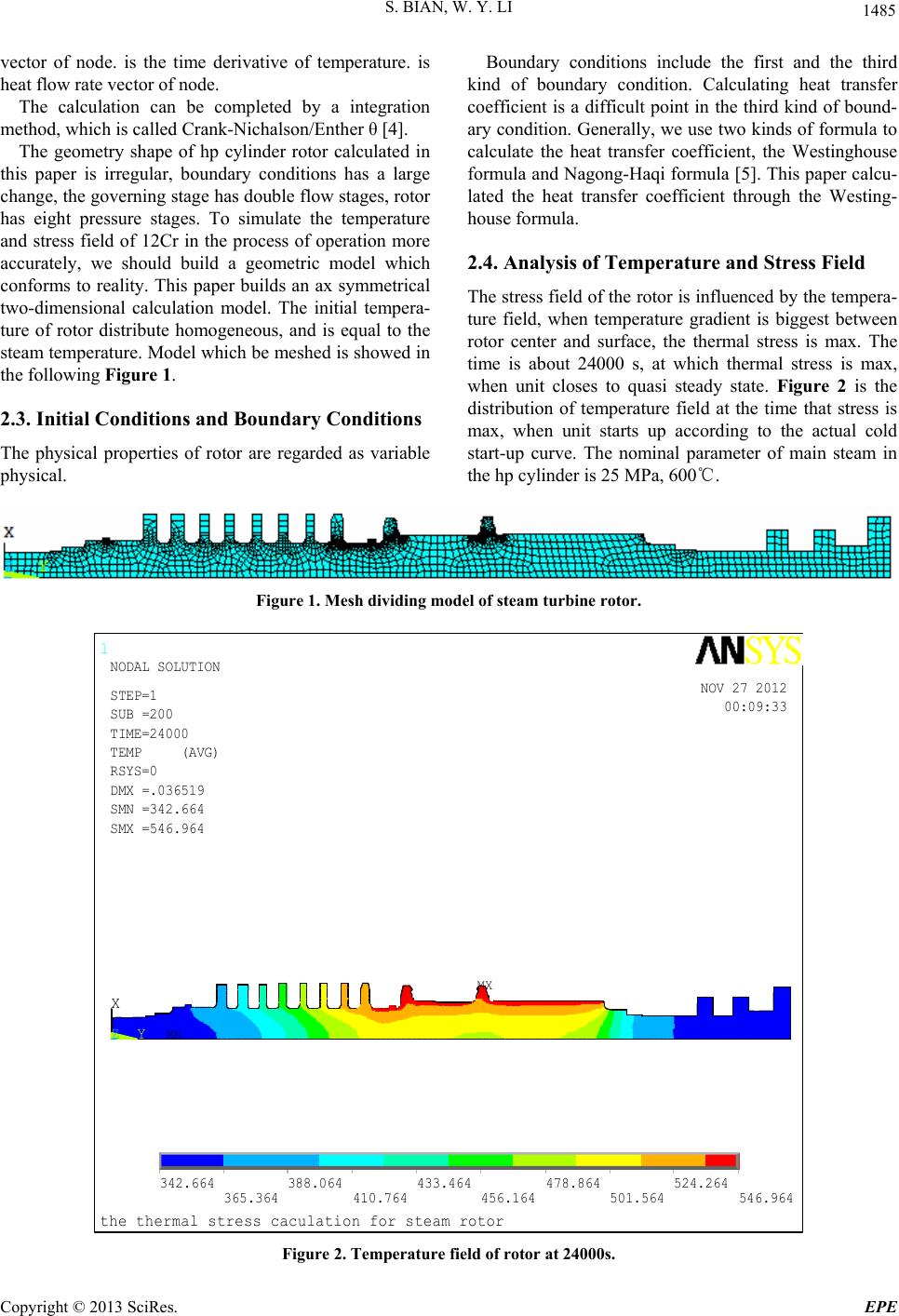 S. BIAN, W. Y. LI 1485 vector of node. is the time derivative of temperature. is heat flow rate vector of node. The calculation can be completed by a integration method, which is called Crank-Nichalson/Enther θ [4]. The geometry shape of hp cylinder rotor calculated in this paper is irregular, boundary conditions has a large change, the governing stage has double flow stages, rotor has eight pressure stages. To simulate the temperature and stress field of 12Cr in the process of operation more accurately, we should build a geometric model which conforms to reality. This paper builds an ax symmetrical two-dimensional calculation model. The initial tempera- ture of rotor distribute homogeneous, and is equal to the steam temperature. Model which be meshed is showed in the following Figure 1. 2.3. Initial Conditions and Boundary Conditions The physical properties of rotor are regarded as variable physical. Boundary conditions include the first and the third kind of boundary condition. Calculating heat transfer coefficient is a difficult point in the third kind of bound- ary condition. Generally, we use two kinds of formula to calculate the heat transfer coefficient, the Westinghouse formula and Nagong-Haqi formula [5]. This paper calcu- lated the heat transfer coefficient through the Westing- house formula. 2.4. Analysis of Temperature and Stress Field The stress field of the rotor is influenced by the tempera- ture field, when temperature gradient is biggest between rotor center and surface, the thermal stress is max. The time is about 24000 s, at which thermal stress is max, when unit closes to quasi steady state. Figure 2 is the distribution of temperature field at the time that stress is max, when unit starts up according to the actual cold start-up curve. The nominal parameter of main steam in the hp cylinder is 25 MPa, 600℃. Figure 1. Mesh dividing model of steam turbine rotor. 1 MN MX X YZ the thermal stress caculation for steam rotor 342.664 365.364 388.064 410.764 433.464 456.164 478.864 501.564 524.264 546.964 NOV 27 2012 00:09:33 NODAL SOLUTION STEP=1 SUB =200 TIME=24000 TEMP (AVG) RSYS=0 DMX =.036519 SMN =342.664 SMX =546.964 Figure 2. Temperature field of rotor at 24000s. Copyright © 2013 SciRes. EPE  S. BIAN, W. Y. LI. 1486 Figure 3 is the distribution of stress field at the time that stress is max, when unit starts up according to the actual cold start-up curve. As can be seen from the grapy, the stress concentration is large near the impeller root of governing stage, whose thermal stress is largest. According to the analysis of the temperature and stress field of rotor, when unit starts up in the cold state, we can see the position whose thermal stress is largest is the im- peller root of governing stage. Analyzing this position, this paper get the temperature-time and stress-time curves of impeller root of governing stage, shown in the following Figure 4 and Figure 5. Figure 5 shows that thermal stress has been on the rise in the startup process. When starting time reaches to 200min, the rotation rate of rotor ascend to 3000r/min, steam temperature changes faster, and stress increases speedly. Up to rated load, the stress trend tends to be gentle. When the steam temperature is kept constant, rotor temperature gradient decreases gradually, rotor stress begins to decline. Figure 3. Stress distribution of rotor at 24000s. Figure 4. Temperature curve varying with time in the cold start-up condition. Copyright © 2013 SciRes. EPE  S. BIAN, W. Y. LI 1487 Figure 5. Stress curve varying with time in the cold start-up condition. Figure 6. Temperature curve varying with time during shut-down period. 2.5. Condition of Shut-down The pulling stress and mechanical stress of the rotor have the same direction when the unit is shutdown, thus stress is easy be large. We should control the change rate of temperature in the shutdown process. Figure 6 is the temperature curve varying with time Copyright © 2013 SciRes. EPE 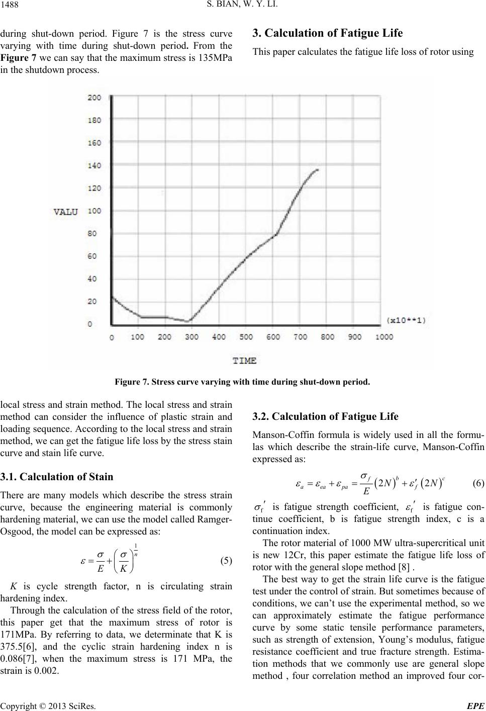 S. BIAN, W. Y. LI. 1488 during shut-down period. Figure 7 is the stress curve varying with time during shut-down period. From the Figure 7 we can say that the maximum stress is 135MPa in the shutdown process. 3. Calculation of Fatigue Life T his paper calculates the fatigue life loss of rotor using Figure 7. Stress curve varying with time during shut-down period. local stress and strain method. The local stress and strain method can consider the influence of plastic strain and loading sequence. According to the local stress and strain method, we can get the fatigue life loss by the stress stain curve and stain life curve. 3.1. Calculation of Stain There are many models which describe the stress strain curve, because the engineering material is commonly hardening material, we can use the model called Ramger- Osgood, the model can be expressed as: 1 n EK (5) K is cycle strength factor, n is circulating strain hardening index. Through the calculation of the stress field of the rotor, this paper get that the maximum stress of rotor is 171MPa. By referring to data, we determinate that K is 375.5[6], and the cyclic strain hardening index n is 0.086[7], when the maximum stress is 171 MPa, the strain is 0.002. 3.2. Calculation of Fatigue Life Manson-Coffin formula is widely used in all the formu- las which describe the strain-life curve, Manson-Coffin expressed as: 22 b f aeapa f N E c N (6) f is fatigue strength coefficient, f is fatigue con- tinue coefficient, b is fatigue strength index, c is a continuation index. The rotor material of 1000 MW ultra-supercritical unit is new 12Cr, this paper estimate the fatigue life loss of rotor with the general slope method [8] . The best way to get the strain life curve is the fatigue test under the control of strain. But sometimes because of conditions, we can’t use the experimental method, so we can approximately estimate the fatigue performance curve by some static tensile performance parameters, such as strength of extension, Young’s modulus, fatigue resistance coefficient and true fracture strength. Estima- tion methods that we commonly use are general slope method , four correlation method an improved four cor- Copyright © 2013 SciRes. EPE 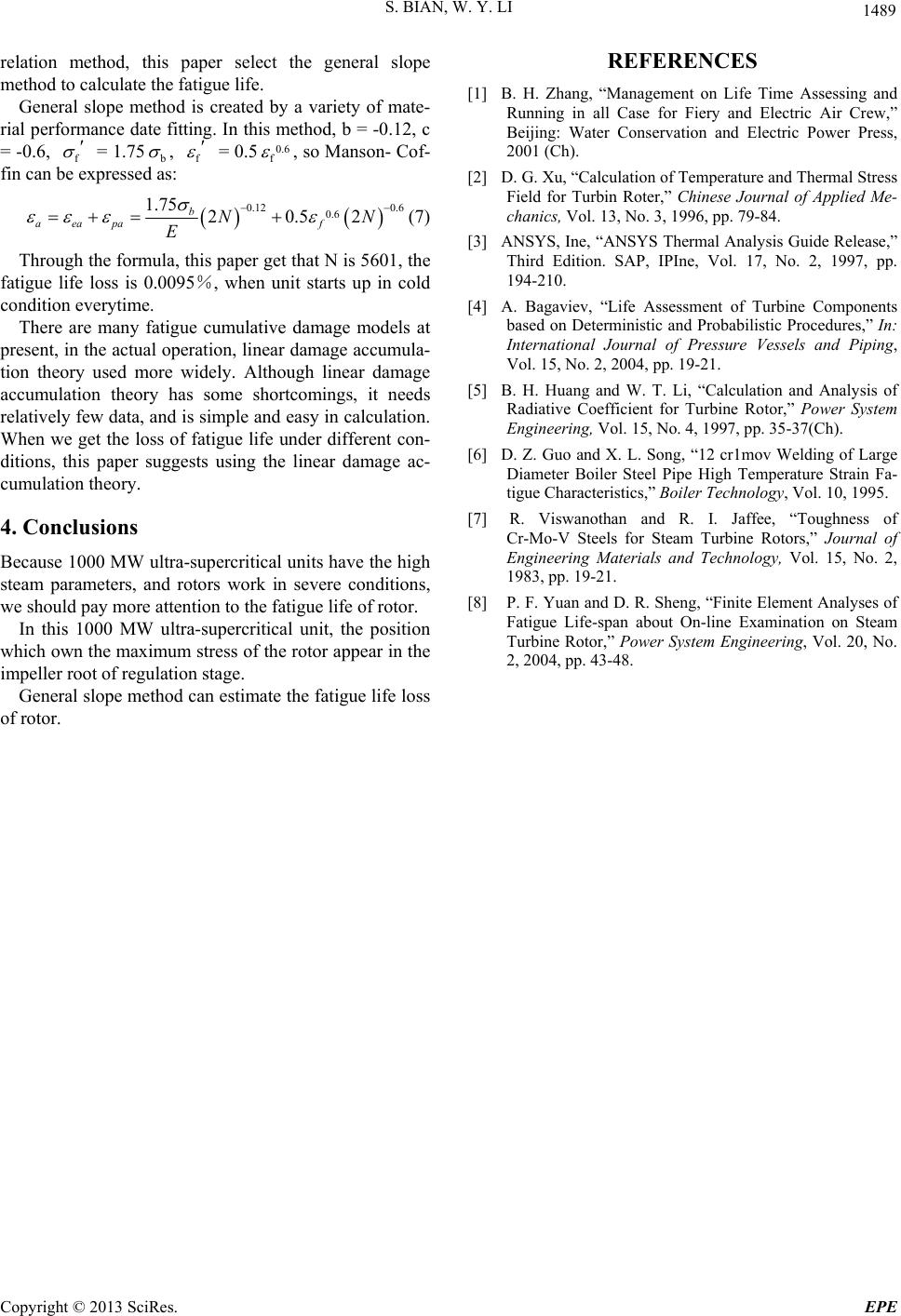 S. BIAN, W. Y. LI 1489 relation method, this paper select the general slope method to calculate the fatigue life. General slope method is created by a variety of mate- rial performance date fitting. In this method, b = -0.12, c = -0.6, f = 1.75 b , f = 0.50.6 f , so Manson- Cof- fin can be expressed as: 0.12 0.6 0.6 1.75 20.52 b aeapa f NN E (7) Through the formula, this paper get that N is 5601, the fatigue life loss is 0.0095%, when unit starts up in cold condition everytime. There are many fatigue cumulative damage models at present, in the actual operation, linear damage accumula- tion theory used more widely. Although linear damage accumulation theory has some shortcomings, it needs relatively few data, and is simple and easy in calculation. When we get the loss of fatigue life under different con- ditions, this paper suggests using the linear damage ac- cumulation theory. 4. Conclusions Because 1000 MW ultra-supercritical units have the high steam parameters, and rotors work in severe conditions, we should pay more attention to the fatigue life of rotor. In this 1000 MW ultra-supercritical unit, the position which own the maximum stress of the rotor appear in the impeller root of regulation stage. General slope method can estimate the fatigue life loss of rotor. REFERENCES [1] B. H. Zhang, “Management on Life Time Assessing and Running in all Case for Fiery and Electric Air Crew,” Beijing: Water Conservation and Electric Power Press, 2001 (Ch). [2] D. G. Xu, “Calculation of Temperature and Thermal Stress Field for Turbin Roter,” Chinese Journal of Applied Me- chanics, Vol. 13, No. 3, 1996, pp. 79-84. [3] ANSYS, Ine, “ANSYS Thermal Analysis Guide Release,” Third Edition. SAP, IPIne, Vol. 17, No. 2, 1997, pp. 194-210. [4] A. Bagaviev, “Life Assessment of Turbine Components based on Deterministic and Probabilistic Procedures,” In: International Journal of Pressure Vessels and Piping, Vol. 15, No. 2, 2004, pp. 19-21. [5] B. H. Huang and W. T. Li, “Calculation and Analysis of Radiative Coefficient for Turbine Rotor,” Power System Engineering, Vol. 15, No. 4, 1997, pp. 35-37(Ch). [6] D. Z. Guo and X. L. Song, “12 cr1mov Welding of Large Diameter Boiler Steel Pipe High Temperature Strain Fa- tigue Characteristics,” Boiler Technology, Vol. 10, 1995. [7] R. Viswanothan and R. I. Jaffee, “Toughness of Cr-Mo-V Steels for Steam Turbine Rotors,” Journal of Engineering Materials and Technology, Vol. 15, No. 2, 1983, pp. 19-21. [8] P. F. Yuan and D. R. Sheng, “Finite Element Analyses of Fatigue Life-span about On-line Examination on Steam Turbine Rotor,” Power System Engineering, Vol. 20, No. 2, 2004, pp. 43-48. Copyright © 2013 SciRes. EPE |