C. M. JR ET AL.
1458
The Brazilian ISO (ONS) will identify when the lines
that will form the AC-Link can be disconnected without
jeopardizing the Brazilian electrical system. The period
when these interconnections have low power flow will be
chosen to perform the test. As explained, the test is
planned to be as short as possible and it should not last
more than 2 to 3 hours, comprising the experiment setup,
the sequence of energization and finally the system res-
toration.
Traditional soil representation was applied during the
tests, specifically the soil resistivity was considered con-
stant with frequency over the entire length of the
AC-Link trunk with value of 4000 Ω.m due to high soil
resistivity in these regions [10].
3. Electromagnetic Transient Studies
For the implementation of the energization maneuver the
regular transient studies were performed in PSCAD, as
described in the following sections.
Due to the line length the overvoltages are expected to
be much lower than the ones observed in regular trans-
mission lines of few hundreds of kilometers long. This
occurs because the traveling waves are attenuated as they
travel along the line, mainly the zero sequence one.
The lines were modeled with the phase domain model
which properly represents the line longitudinal parame-
ters frequency dependence.
3.1. Line Energization Without Faults
The insulation level of the 500 kV lines and the equip-
ment connected in the test system were not surpassed
during the energization tests.
The surge arresters that were kept connected during
the simulations did not affect the AC-Link behavior as
the results were similar to the configuration when they
were considered just in the AC-Link terminals.
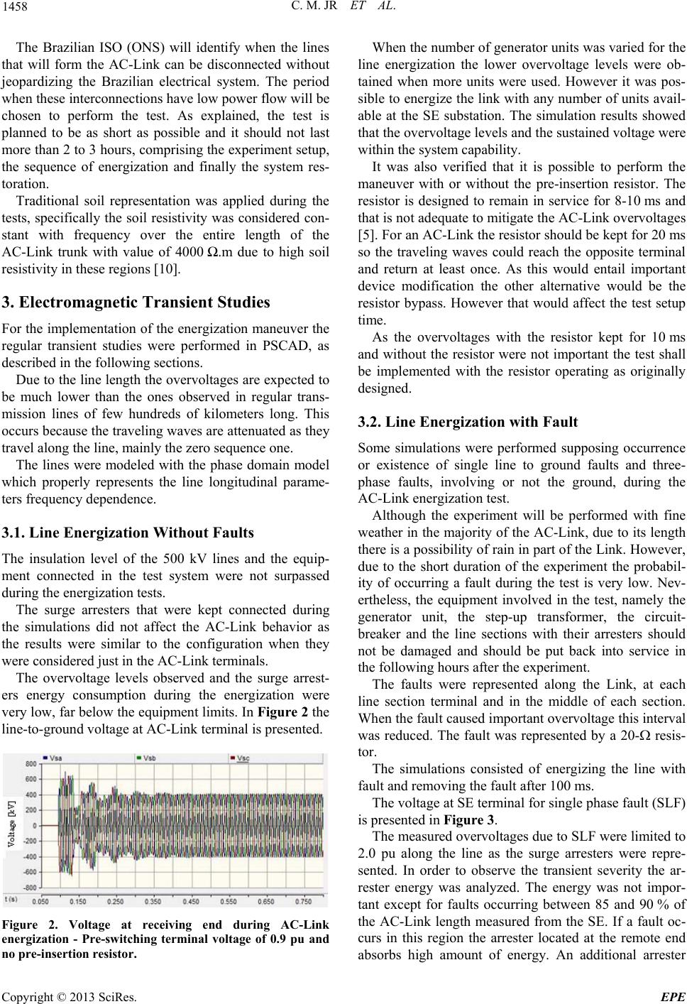
The overvoltage levels observed and the surge arrest-
ers energy consumption during the energization were
very low, far below the equipment limits. In Figure 2 the
line-to-ground voltage at AC-Link terminal is presented.
Figure 2. Voltage at receiving end during AC-Link
energization - Pre-switching terminal voltage of 0.9 pu and
no pre-insertion resistor.
When the number of generator units was varied for the
line energization the lower overvoltage levels were ob-
tained when more units were used. However it was pos-
sible to energize the link with any number of units avail-
able at the SE substation. The simulation results showed
that the overvoltage levels and the sustained voltage were
within the system capability.
It was also verified that it is possible to perform the
maneuver with or without the pre-insertion resistor. The
resistor is designed to remain in service for 8-10 ms and
that is not adequate to mitigate the AC-Link overvoltages
[5]. For an AC-Link the resistor should be kept for 20 ms
so the traveling waves could reach the opposite terminal
and return at least once. As this would entail important
device modification the other alternative would be the
resistor bypass. However that would affect the test setup
time.
As the overvoltages with the resistor kept for 10 ms
and without the resistor were not important the test shall
be implemented with the resistor operating as originally
designed.
3.2. Line Energization with Fault
Some simulations were performed supposing occurrence
or existence of single line to ground faults and three-
phase faults, involving or not the ground, during the
AC-Link energization test.
Although the experiment will be performed with fine
weather in the majority of the AC-Link, due to its length
there is a possibility of rain in part of the Link. However,
due to the short duration of the experiment the probabil-
ity of occurring a fault during the test is very low. Nev-
ertheless, the equipment involved in the test, namely the
generator unit, the step-up transformer, the circuit-
breaker and the line sections with their arresters should
not be damaged and should be put back into service in
the following hours after the experiment.
The faults were represented along the Link, at each
line section terminal and in the middle of each section.
When the fault caused important overvoltage this interval
was reduced. The fault was represented by a 20- resis-
tor.
The simulations consisted of energizing the line with
fault and removing the fault after 100 ms.
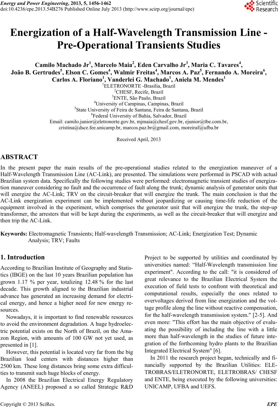
The voltage at SE terminal for single phase fault (SLF)
is presented in Figure 3.
The measured overvoltages due to SLF were limited to
2.0 pu along the line as the surge arresters were repre-
sented. In order to observe the transient severity the ar-
rester energy was analyzed. The energy was not impor-
tant except for faults occurring between 85 and 90 % of
the AC-Link length measured from the SE. If a fault oc-
curs in this region the arrester located at the remote end
absorbs high amount of energy. An additional arrester
Copyright © 2013 SciRes. EPE