H. P. XU ET AL.
1412
density.
Taking no account of the magnetic leakage and iron
loss, the reactance of SR is
22
b
ac
ac ac
An An
dB
L
ldH l
eHe
(2)
where, A is the area of the section of the core (cm2), ac
is the number of the SR’s work winding, is the
average length of the magnetic circuit (cm) [11].
n
l
For simplify, the SR is considered as a controllable
nonlinear reactor, and it keeps constant if the system is
steady. All setting values of the current of rectifier units
are supposed as equal, the sum of them is the setting
value of the electrolytic series current, that is, ref
. The error between
ref
dc
NIref
dc
and dc
, the measured
value of the series current, is as the input of the PI
controller, and the output from PI controller is added to
the setting value of SR’s inductance , the sum is the
actual inductance after the regulation of SR.
ref
L
The control diagram of the SR is shown in Figure 3.
and T are the proportional gain and integral time
constant of PI controller.
Due to the magnetic characteristics of the SR, the
regulating range is limited. It makes the regulating range
of the outputting dc voltage on the load bus limited. In
general, the regulator depth is about 70 V, and the
regulation could be carried out continuously.
3.2. Control Strategy of OLTC
In this paper, the voltage range of fineness regulation is
[0, ΔUmax], the range is divided into three sections. The
first section is [0, U1], called up shift section; the second
section is [U1, U2], called unrestrained section; the third
is [U2, ΔUmax], called downshift section. The voltage
range of unrestrained section is almost 1.5 times as the
voltage change one step of OLTC caused, and the
voltage range of up shift or downshift section can meet
the requirements of the common fluctuation. For
example, the voltage range of downshift section should
cover the voltage change an anode effect caused.
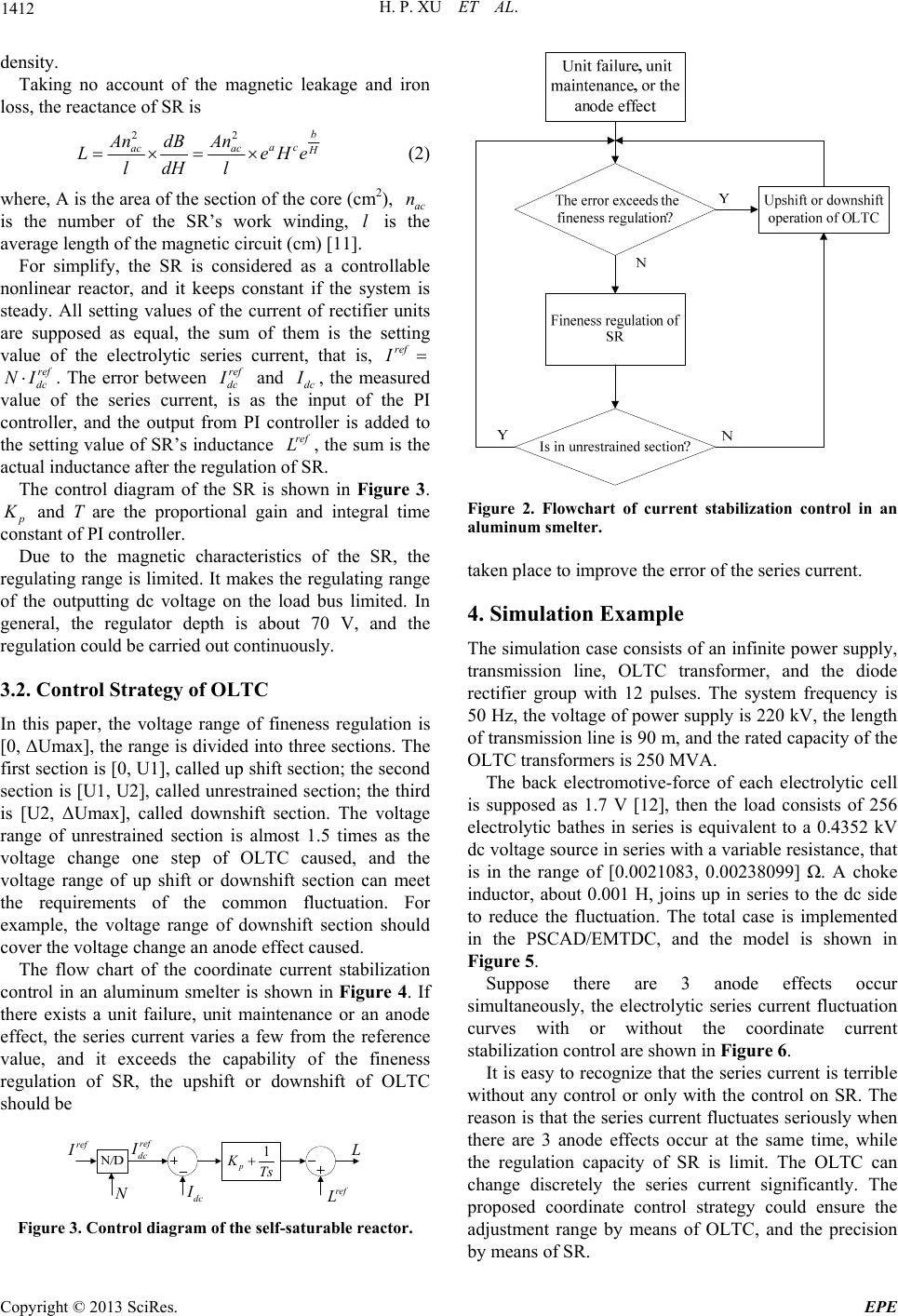
The flow chart of the coordinate current stabilization
control in an aluminum smelter is shown in Figure 4. If
there exists a unit failure, unit maintenance or an anode
effect, the series current varies a few from the reference
value, and it exceeds the capability of the fineness
regulation of SR, the upshift or downshift of OLTC
should be
ref
I
ref
dc
I
dc
I
ref
L
1
p
KTs
Figure 3. Control diagram of the self-saturable reactor.
Figure 2. Flowchart of current stabilization control in an
aluminum smelter.
taken place to improve the error of the series current.
4. Simulation Example
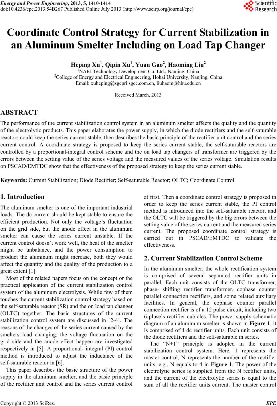
The simulation case consists of an infinite power supply,
transmission line, OLTC transformer, and the diode
rectifier group with 12 pulses. The system frequency is
50 Hz, the voltage of power supply is 220 kV, the length
of transmission line is 90 m, and the rated capacity of the
OLTC transformers is 250 MVA.
The back electromotive-force of each electrolytic cell
is supposed as 1.7 V [12], then the load consists of 256
electrolytic bathes in series is equivalent to a 0.4352 kV
dc voltage source in series with a variable resistance, that
is in the range of [0.0021083, 0.00238099] Ω. A choke
inductor, about 0.001 H, joins up in series to the dc side
to reduce the fluctuation. The total case is implemented
in the PSCAD/EMTDC, and the model is shown in
Figure 5.
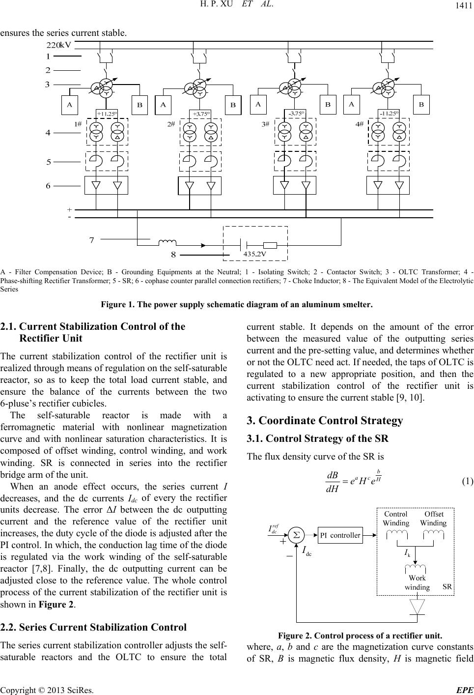
Suppose there are 3 anode effects occur
simultaneously, the electrolytic series current fluctuation
curves with or without the coordinate current
stabilization control are shown in Figure 6.
It is easy to recognize that the series current is terrible
without any control or only with the control on SR. The
reason is that the series current fluctuates seriously when
there are 3 anode effects occur at the same time, while
the regulation capacity of SR is limit. The OLTC can
change discretely the series current significantly. The
proposed coordinate control strategy could ensure the
adjustment range by means of OLTC, and the precision
by means of SR.
Copyright © 2013 SciRes. EPE