Paper Menu >>
Journal Menu >>
 Energy and Power Engineering, 2013, 5, 1387-1392 doi:10.4236/epe.2013.54B263 Published Online July 2013 (http://www.scirp.org/journal/epe) Performance Analysis of Induced Draft Fan Driven by Steam Turbine for 1000 MW Power Units Jianling Deng, Feifei Liang, Yang Ding, Zhiping Yang, Gang Xu, Jizhen Liu National thermal power engineering technology research center, North China Electric Power University, Beijing, China Email: xgncepu@163.com Received March, 2013 ABSTRACT Boiler fan is the main power consumption device in thermal power units and the induced draft fan accounted for the largest proportion. Reducing the energy consumption rate of induced draft fan is the main path to reduce the power consumption rate of thermal power units. The induce fan driven by small turbine is greatly effective for reducing the power consumption rate and the supply coal consumption rate in large thermal power plant. Take 1000 MW power units for example, the selection of steam source for steam turbine were discussed and economic performance of the unit un- der different steam source was compared in this paper. The result shows that compared with the motor driven method, there is about 1.6 g/kWh decrease in supply coal consumption rate driven by the fourth stage extraction steam; whereas there is about 2.5 g/kWh decrease in supply coal consumption rate driven by the fifth stage extraction steam. Keywords: Induced Draft Fan; Source Steam; Auxiliary Power Ratio ; Supply Coal Consumption Rate; Investment Recovery Period 1. Introduction Auxiliary power ratio is a crucial indicator to the evalua- tion of thermal power unit, it directly affects the supply coal consumption rate of the power unit. Boiler fan plays an important role in fossil-fired power unit’s auxiliary power consumption and it occupies about 40% of total auxiliary power consumption, among which induced draft fan (ID fan) consumes approximately 20% (15% for primary air fan, and the rest 5% for blower). Generally, fan operation and regulation could be achieved by ad- justing baffle or the rotation angle of diverter guide blade, which in turn results in massive power consumption be- cause of throttling loss. Therefore, in order to improve system efficiency as well as reduce energy consumption, energy-saving retrofitting of fan has been one o f the most plausible methods to reduce energy consumption of power plant recently [1-3]. Currently there are several ways to reduce power con- sumption rate of fan, including replace the old fan with high efficiency and energy-saving one (which means to modify the old fan), speed regulation reform, operation optimization and so on. With regard to speed regulation reform, we can either add fluid coupling or frequency converter. Usually frequency converter has better per- formance than fluid coupling, but it requires high in- vestment [4-8]. Operation optimization means when boi- ler works normally, the booster fan is in chain spare state. If boiler malfunctions, the booster fan automatically starts operating, significantly mitigating its own steam consumption. As the largest power consumption device in all kinds of fans, it is imperative to modify ID fan into energy- saving type. Referring to the operating mode that replac- ing motor-driven feed pump with steam-driven feed pump, ID fan driven by small turbine is the major ap- proach to reduce unit auxiliary power ratio [9]. This pa- per gives feasibility analysis of small turbine driven by the fourth stage extraction steam or the fifth stage extrac- tion steam, compares the energy-saving benefit of these two different schemes, then accumulates each scheme’s dynamic investment recovery life based on dynamic in- vestment recovery period theory, during which the valid- ity calculation of each scheme is verified. 2. 1000 MW Unit Induced Draft Fan Profile The 1000 MW unit is equipped with two axial static blade adjustable ID fan, constructed by Chengdu power machinery factory. They are horizontal symmetry ar- ranged, open layout and in parallel operation. Fan model is AN42e6(V19+4˚), it adopts imported static blade reg- ulation, with a blade adjusting range of -75℃~+30˚ (corresponding open feedback indication is 0~100%). Motor type: YKK1120-10, manufactured by Xiangtan motor, rated power is 8000 KW, power factor is 0.87, and rated speed is 596 r/min. Table 1 and Table 2 pre- Copyright © 2013 SciRes. EPE  J. L. DENG ET AL. 1388 sent operating parameters of ID fan driven by motor and small turbine respectively. Comparing fan efficiency in Table 1 and Table 2, it can be found that when ID fan is driven by motor, its efficiency decreases as working load drops, while effi- ciency of ID fan driven by small turbine remains constant in high efficiency area. This is attributed to the fact that when driven by motor, the efficiency curve of ID fan keeps unchanged on account of throttling governing, as the flow rate decreases, its efficiency also drops. While ID fan driven by small turbine, due to variable-speed regulation, ID fan’s efficiency curve will change accord- ingly if rotational speed changes, which assures that the ID fan always operates in high efficiency area. Table 1 and Table 2 also shows that when driven by small turbine, ID fan’s shaft power is lower compared to that driven by motor at constant speed, which happens in each working condition. Thus, the lower the working load, the larger th e reduction. 3. Steam Source Selection and Economic Analysis of ID Fan Driven by Small Turbine 3.1. Steam Source Selection In principle, each stage extraction steam from main tur- bine could be the steam source that drives the ID fan. However, there are some drawbacks if the extraction point is selected before intermediate reheat point: on the one hand, efficiency will drop because steam expansion is at excessive high temperature; on the other hand, water erosion of last stage will be aggravated. Moreover, due to the high pressure of supply steam, inlet steam volume flow of the small turb ine decreases, accounting for height reductio n of flow path no zzle and blad e. To make up the shortages mentioned above, steam that drives the small turbine ought to be extracted from some stage behind intermediate reheat point, in order to reduce final stage steam loss, it is suggested that supply steam pressure be as low as possible. In addition, low extraction steam pressure increases admission volume and improves relative internal efficiency of small turbine, which will further decrease heat consumption rate. Nevertheless, it has to be noted that too low-pressure steam will lead to exhaust area’s excessive enlargement of small turbine’s last stage and restrict rotational speed improvement. Be- sides, bigger leaving velocity loss is highly possible, which may cause relative internal efficiency reduction. So crossover pipe between intermediate pressure and low pressure cylinders of main steam turbine and extraction steam from preceding stage are favorable steam sources for small turbine. Based on existed conditions, available steam sources are the third, the fourth and the fifth stage extraction steams. In the following section, we only discuss the fea- sibility of ID fan driven by the fourth and the fifth stage extraction steam, because high parameters of the third stage extraction steam have strong negative effects. In this paper, the small turbine adopts condensing steam type, its start and backup steams can either come from adjacent engine or auxiliary steam generated by startup boiler room, under normal working condition. The fourth or the fifth stage extraction steam will be used as steam source, there is no need to apply high pressure steam under low working load as supply steam alone can perfectly meets the requirement, auxiliary steam comes from auxiliary steam main pipe of adjoining engine, for each small turbine, an exclusive condenser is deployed, the condenser is cooled down by circulated water, being pressure boosted by the condensing water pump comes with the condenser, th en the water is pumped into the hot well located at main condenser. Table 1. Operating parameters of ID fan when driven by motor. Working condition parameter BMCR THA 75%THA 50%THA 40%THA Inlet flow rate/(m3/s) 686 648 500 357 292 Fan total pressure/Pa 6050 5651 4225 3154 2543 Fan efficiency/% 86.7 83.1 73.1 54.6 43.3 Fan working speed/(r/min) 595 595 595 595 595 Fan shaft power/kW 4787 4407 2890 2063 1715 Table 2. Operating parameters of ID fan when driven by small turbine. Working condition parameter BMCR THA 75%THA 50%THA 40%THA Inlet flow rate/(m3/s) 686 648 500 357 292 Fan total pressure/Pa 6050 5651 4225 3154 2543 Fan efficiency/% 86.7 85.9 85.8 85.8 85.9 Fan working speed/(r/min) 595 562 434 310 253 Fan shaft power/kW 4787 4263 2462 1312 864 Copyright © 2013 SciRes. EPE  J. L. DENG ET AL. 1389 3.2. Economic Analysis In this paper, ID fan driven by small turbine scheme is selected on the ground of variable working condition theory of thermodynamic system [10], with given data such as flow rate of each stage extraction steam from the main turbine, flow rate and parameters of feed water, turbine exhaust steam parameters. Besides, this paper conducts some important thermal economic indicators under two different schemes, including heat consumption rate, power generation coal consumption rate and supply coal consumption rate. 3.2.1. Variable Working Condition Theory of Thermodynamic System During the calculation process of thermodynamic system under variable working conditions, group of stages is served as the calculation unit, and it is categorized by extraction point. The first group of stages covers from high pressure cylinder inlet to the first extraction point, then each two extraction points make one group of stages, the last extraction point to the final stage also make one group of stages. In the following equation (1), flow rate of each group of stages is presented: 01 2 3 4 5 6 7 8 I II I III II IV III VIV VI V VII VI VIII VII DDD DDD DDD DDD DDD DDD DDD DDD (1) where I D to VIII stand for pass flow rate of each unit, 0 is main steam flow rate, and 1 to are flow rates of corresponding stage extraction steam. D DD 8 D If flow rate changes, pressures before and behind each group of stages will change, their relationship could be obtained by Friu Geer formula as follow: 22 1,0 112 22 1,0 1 1,0 2,0 T Dpp DT pp (2) Since temperature correction term 1,0 1 T almost equals to 1, it’s negligible in practical calculations, T 21 is very small, 2 and 2,0 can be ignored because they have little effect on the result, so equation (2) can be simplified as: pp p p 11 1,0 1,0 Dp Dp (3) Then the extraction steam pressure is gained by the following equation: 1 11,0 1,0 D pp D (4) where 1: pressure before the group of stages after working condition is changed; 1,0 : pressure before the group of stages when working condition has not changed; 1: flow rate of the group of stages after working cond i- tion is changed; 1,0 : flow rate of the group of stages when working condition has not switched. pp DD Assuming relative internal efficiency of the group of stages remains unchanged, new extraction steam en- thalpy can be approximated based on linear relation on steam expansion line as pressure before the group of stages (i.e extraction steam pressure) varies, specific equation is: 1,0 2 21,0 1,02,0 1,0 2,0 ( pp hhh h pp ) (5) In equation (5), variables with sub 1, 2 represent data before and behind the group of stages, while variables with sub 0 are values when working condition has not changed. Pressure loss of every extraction steam pipe is deter- mined by formula (6): ,0 ,0 i ii i D pp D (6) where i p and i p are pressure loss of the i’th extrac- tion steam before and after working condition changes respectively, ,0i: flow rate of the i’th extraction steam in the first place, i: flow rate of the i’th extraction steam when working condition changes. DD In the following discussion, exhausted water parame- ters of the heater are acquired provided the assumption that terminal temperature difference and hydrophobic end error keep unchanged in all working condition. 3.2.2. Result and An al y si s In contrast, Changes of economic indicators of unit dri- ven by small turbine are listed in Table 4: It is demonstrated in Table 4 that when ID fan driven by small turbine instead of motor, the standard coal consumption rate increases, but auxiliary power ratio and supply standard coal consumption are decreasing. When adopting the fourth stage extraction steam as the steam source, power generation standard coal consump- tion increases by about 3 g/KWh, auxiliary power ratio has a reduction by 1.5%, and supply standard coal con- sumption also reduces by about 1.6 g/KWh; Whereas if the fifth stage extraction steam is applied, there is about 2 g/KWh increase in generation standard coal consump- tion, supply standard coal consumption has about 2 g/KWh cut down. So compared to the fourth stage ex- Copyright © 2013 SciRes. EPE  J. L. DENG ET AL. 1390 traction steam scheme, the fifth stage extraction steam scheme has an obvious reduction in supply coal con- sumption but requires less standard coal to realize the same power output, which means it has better economic performance. Table 5 shows inlet flow rate of small turbine under tw n using the fifth stage extrac- tio Table 3. Economic indicators of Unit of three driven methods. Power genera tion standard coal Auxiliary power Supply standard coal o steam source methods. Table 5 implies that whe n steam as steam source, to a rather small extent, the inlet flow rate of small turbine will increase, for example, under BMCR working condition; only 25.69t steam is required per hour, so it is completely feasible to use the fifth stage extraction steam as the steam source of small turbine. Figures 1, 2 and 3 respectively presents comparison of coal consumption rate, auxiliary power ratio and supply coal consumption rate under three schemes when ID fan driven by small turbine, althou gh there is a mild increase in unit coal consumption rate, both auxiliary power ratio and supply standard coal consumption rate are decreasing. Besides, if the fifth stage extraction steam is selected as the steam source of small turbine, more standard coal could be saved realizing the same power output, with better energy efficiency. consumption/(g/kWh) ratio/% consumption/(g/kWh) Working scheme1 scheme2 scheme 3 scheme1 scheme2 scheme3 scheme1 scheme2 scheme3 condition BMCR 272.20 274.96 274.13 4.22 2.72 2.72 284.20 282.65 281.79 THA 272.50 275.47 274.80 4.22 2.60 2.60 284.50 282.82 282.14 75%THA 276.61 278.97 278.15 4.50 3.14 3.14 289.64 288.02 287.17 50%THA 286.17 289.34 288.46 4.70 3.08 3.08 300.28 298.53 297.63 40%THA 297.89 301.32 300.15 4.90 3.31 3.31 313.24 311.64 310.43 Table 4. Changes of economic indicators of Unit driven by small turbine. Working condition Indicator/unit BMCR THA 50%THA 40%THA 75%THA Power generation standard +2.76 +1.93+2.97 +2.30+2.36 +1.54+3.17 +2.29 +3.43 +2.26 coal consumption/(g/kWh) Auxiliary power ratio/% -1.50 -1.50 -1.62 -1.62 -1.36 -1.36 -1.62 -1.62 -1.59 -1.59 supply standard coal -1.55 -2.41 -1.68 -2.36 -1.62 -2.47 -1.75 -2.65 -1.60 -2.81 consumption/(g/kWh) notes on the left side refer to changes of economic indicators of unit driven by small turbine when the fourth stage extraction steam is Table 5. Inlet flow rate of small turbine under two steam source methods. Working Inlet flow rate of small turbine extr/) Inlet flow rate of small turbine wh Difference(the fifth stage fo : in the table above, figure applied, while the right side refer to the fifth stage extraction steam. condition when using the fourth stage athction steam as steam source/(en using the fifth stage extraction steam as steam source /(t/h) extraction steam minus the urth stage extraction steam) BMCR 21.88 25.69 3.81 THA 19.81 23.30 3.49 75%THA 12.30 17.08 4.78 50%THA 6.47 9.90 3.43 40%THA 4.36 5.39 1.03 Copyright © 2013 SciRes. EPE 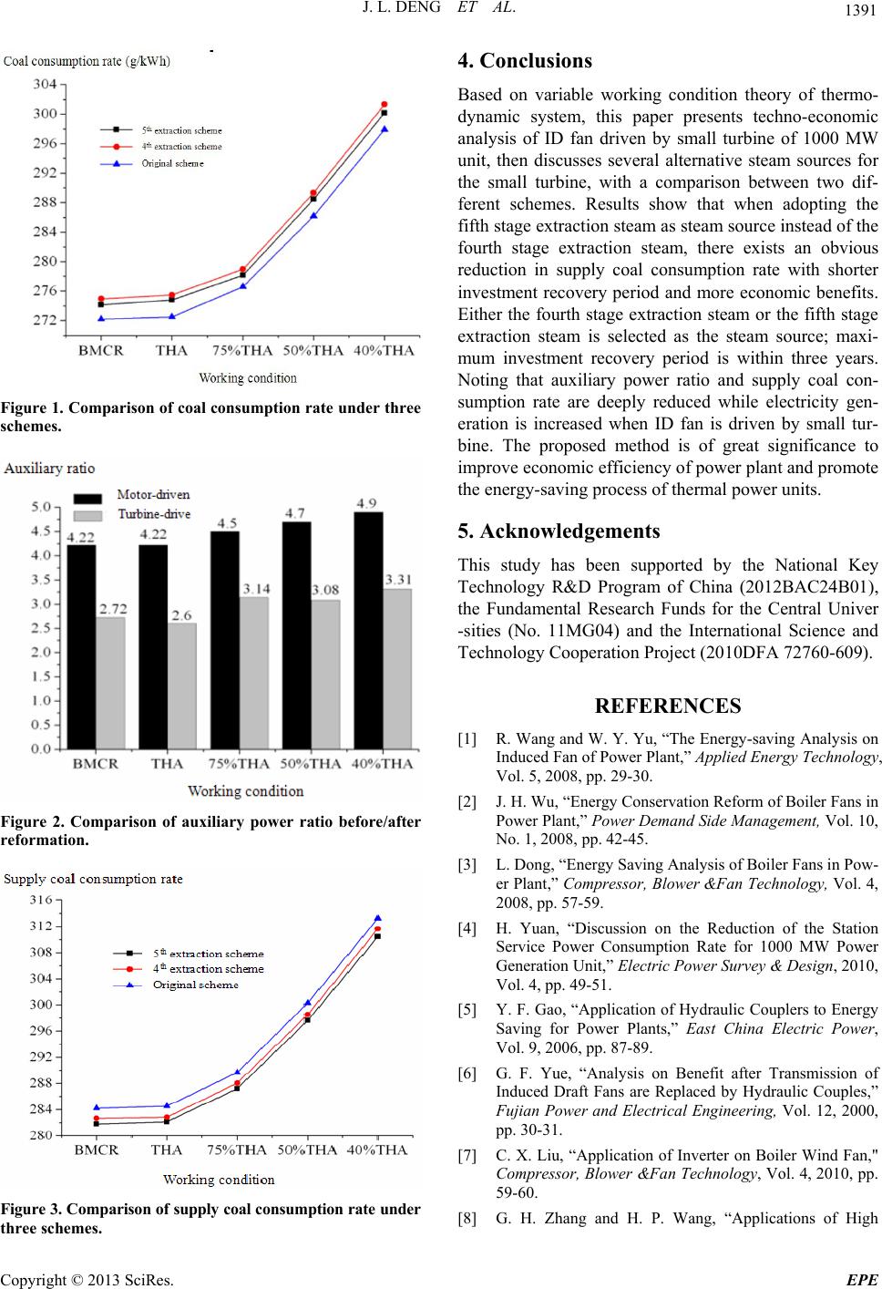 J. L. DENG ET AL. 1391 Figure 1. Comparison of coal consumption r ate under three schemes. Figure 2. Comparison of auxiliary power ratio before/after reformation. Figure 3. Comparison of supply c oal consum ption rate under three schemes. 4. Conclusions Based on variable working condition theory of thermo- ven by small turbine of 1000 MW several alternative steam sources for B01), unds for the Central Univer e International Science and , Vol. 5, 2008, pp [2] J. H. Wu, “Enm of Boiler Fans in Analysis of Boiler Fans in Pow- n the Reduction of the Station sis on Benefit after Transmission of ng and H. P. Wang, “Applications of High dynamic system, this paper presents techno-economic analysis of ID fan dri unit, then discusses the small turbine, with a comparison between two dif- ferent schemes. Results show that when adopting the fifth stage extraction steam as steam source instead of the fourth stage extraction steam, there exists an obvious reduction in supply coal consumption rate with shorter investment recovery period and more economic benefits. Either the fourth stage extraction steam or the fifth stage extraction steam is selected as the steam source; maxi- mum investment recovery period is within three years. Noting that auxiliary power ratio and supply coal con- sumption rate are deeply reduced while electricity gen- eration is increased when ID fan is driven by small tur- bine. The proposed method is of great significance to improve economic efficiency o f power plant and promote the energy-saving process of thermal power units. 5. Acknowledgements This study has been supported by the National Key Technology R&D Program of China (2012BAC24 the Fundamental Research F -sities (No. 11MG04) and th Technology Cooperation Project (2010DFA 72760-609). REFERENCES [1] R. Wang and W. Y. Yu, “The Energy-saving Analysis on Induced Fan of Power Plant,” Applied Energy Technology . 29-30. ergy Conservation Refor Power Plant,” Power Demand Side Management, Vol. 10, No. 1, 2008, pp. 42-45. [3] L. Dong, “Energy Saving er Plant,” Compressor, Blower &Fan Technology, Vol. 4, 2008, pp. 57-59. [4] H. Yuan, “Discussion o Service Power Consumption Rate for 1000 MW Power Generation Unit,” Electric Power Survey & Design, 2010, Vol. 4, pp. 49-51. [5] Y. F. Gao, “Application of Hydraulic Couplers to Energy Saving for Power Plants,” East China Electric Power, Vol. 9, 2006, pp. 87-89. [6] G. F. Yue, “Analy Induced Draft Fans are Replaced by Hydraulic Couples,” Fujian Power and Electrical Engineering, Vol. 12, 2000, pp. 30-31. [7] C. X. Liu, “Application of Inverter on Boiler Wind Fan," Compressor, Blower &Fan Technology, Vol. 4, 2010, pp. 59-60. [8] G. H. Zha Copyright © 2013 SciRes. EPE  J. L. DENG ET AL. 1392 Voltage Inverter on Boiler Fans in Power Plant,” Coal Science & Technology Magazine, Vol. 1, 2009, pp. 51-52. [9] P. Zhang, “Discussion on the System of Turbine-Driven. Tec Induced Fan of Power Generation Unit,” Applied Energy hnology, Vol. 8, 2010, pp. 17-19. [10] T. K. Zheng, “Thermal Power Units,” China Electric Power Press, Beijing, 2001, pp. 63-64 Copyright © 2013 SciRes. EPE |