Paper Menu >>
Journal Menu >>
 Wireless Sensor Network, 2009, 1, 1-60 Published Online April 2009 in SciRes (http://www.SciRP.org/journal/wsn/). Copyright © 2009 SciRes. Wireless Sensor Network, 2009, 1, 1-60 Extending the Network Lifetime Using Optimized Energy Efficient Cross Layer Module (OEEXLM) in Wireless Sensor Networks T. V. Padmavathy Department of Electronics and Communication Engineering, SSN College of Engineering, Chennai, India Email: Padmavathytv@ssn.edu.in Received February 11, 2009; revised March 10, 2009; accepted March 13, 2009 Abstract In wireless sensor network, the primary design is to save the energy consumption as much as possible while achieving the given task. Most of recent researches works have only focused on the individual layer issues and ignore the importance of inter working between different layers in a sensor network. In this paper, we use a cross-layer approach to propose an energy-efficient and extending the life time of the sensor network. This protocol which uses routing in the network layer, and the data scheduling in MAC layer. The main ob- jective of this paper is to provide a possible and flexible approach to solve the conflicts between the require- ments of large scale, long life-time, and multi-purpose wireless sensor networks. This OEEXLM module gives better performance compared to all other existing protocols. The performance of OEEXLM module compared with S-MAC and directed diffusion protocol. Keywords: Routing, Medium Access Control, Life Time of the Network, Energy Efficiency, OEEXLM Module, Wireless Sensor Networks 1. Introduction Wireless sensor network consists of large number of sensor nodes are randomly distributed in a region. Each node has a limited energy supply and generates informa- tion when ever event occurs that needs to be communi- cated to a sink node. The focus of this paper is on the computation of optimal energy usage for data transfer and link schedule that maximize the network lifetime. However most wireless sensor network energy consump- tion operations involve sensing, computing, and communi- cating [1]. Generally, communication between nodes con- sumes more energy than local processing or collecting data operation. The geographical nature of the deployment space of nodes makes quasi impossible the replacement or the recharging operations of batteries. The challenge is to economize energy inside every node in order to maintain as long as possible the network functionality. 2. Related Works Many research works are developed for energy effi- ciency at each layer of protocol stack by proposing new algorithms and protocols. In particular, MAC layer was of great interest for many researchers because it is con- sidered as an important source of energy wastage such as overhearing, collision, control packet overheads and idle listening [2]. In order to decrease or if possible to eliminate these various sources of energy wastage, several protocols has been proposed during last years and which are divided into two main classes: Schedule based protocol TDMA and Contention based protocol. In TDMA protocols [3] are employed to avoid colli- sions by associating a slot time for each sensor node in a given cluster. This protocols more complex in the WSN where the nodes in general have a same priority and very limited resources. The Contention-based protocols are known as CSMA-based are usually used in the multi- hop wireless networking. But this protocol generates collisions due to these useless retransmissions which cause energy consumption wastage and time consuming in data transmission. Some of the power control problems are discussed in [4,5]. Approaches at MAC layer are Dermikol et al. [4] infers that some pros and cons of the some of the exist- ing protocol. One of the first attempts at MAC protocol for WSN is PAMAS, which reserves battery power in-  28 T. V. PADMAVATHY ET AL. Copyright © 2009 SciRes. Wireless Sensor Network, 2009, 1, 1-60 telligently powering off users that are not actively transmitting or receiving packets. This protocol de- creased the energy consumption of the network but maximum latency occurs. Raghavendra et al. [5] the Power Aware Medium Access protocol and Signaling (PAMAS) is a CSMA based protocol in which the nodes that are not actively transmitting or receiving should power themselves off. The protocol requires the nodes to have two separate channels (control and data), which will require two radios at each node increasing the cost, size and complexity of the sensor design. Existing MAC protocol [6,7] turn off the transceiver when there is no communication between the nodes also the power savings in these papers results reducing the idle listening power but also decreasing the collisions. In these papers they proposed adaptive listening incurs overhearing. Sleep and listen periods are predefined and constant, which decreases the efficiency of the algorithm under variable traffic load. A new generation of MAC protocols that is Cross- layer MAC protocols using several layers in order to optimize energy consumption has been emerged. These layers can be divided into interaction mode or unification mode. In the interaction mode, the MAC protocol is built by exploiting the data generated by other adjacent layers. Approaches at network layer in WSNs are mostly used to implement the routing of the incoming data, as quoted in [8]. It is known that generally in multihop networks the source nodes cannot reach the sink directly. Therefore, intermediate sensor nodes have to relay their packets. Generally, the implementation of routing tables offers the solution. These routing tables contain lists of node options for any given packet destination Definition of the routing tables is the task of the routing algorithm along with the help of the routing protocol for their con- struction and maintenance. MAC-CROSS Protocol [9] is an example of Cross- layer approach which allows the interaction between MAC and information of the network layers by making only the communicating nodes in listening mode and by putting other nodes into sleep mode. In order to avoid collisions, MAC-CROSS uses the control messages RTS/CTS/ACK. On the other hand, a Cross-layer design mode by unification requires the development of only one layer including at the same time functionalities of considered layers. In this paper, a unified cross layer module XLM [10] is developed which achieves efficient and reliable event communication between the nodes with minimum en- ergy expenditure. But in this protocol the end-to-end delay increases for low value duty cycle. When the duty cycle is low =0.1, 14% of the transmitted packets are dropped due to retransmission timeout. Because sender nodes cannot find any neighbors that satisfy the constraints. Weiyan Ge et al. [11] addressed the rate optimization for multicast communications at the media access con- trol (MAC) layer, and explore transport layer erasure coding to enhance multicast reliability in wireless sensor networks. In this approach they are not addressed the energy consumption and end-to-end delay. 3. Proposed OEEXLM Module The proposed cross layer approach replaces the entire traditional layer protocol architecture that has been so far used in WSNs. In this protocol we integrate the me- dium access control and routing to improve the perform- ance of the network. The communication in OEEXLM module is based on initiative concept. This module al- lows the each node to decide whether it can participate in communication or not. Consequently, this protocol uses adaptive receiving, stagger scheduling algorithm and logical link decision algorithm. A node starts a transmission by transmitting to its neighborhood an RTS packet to indicate that it has a packet to send. Upon receiving an RTS packet, each neighborhood node i decide to participate to communi- cation or not, that decision can be determined by an ini- tiative “I” defined as follows: I= 1 0 th thd rev rev TAR T if EE otherwise ⎧>+ ⎛⎞ ⎪⎜⎟ β= γ=γ ⎪⎜⎟ ⎨⎜⎟ = ⎝⎠ ⎪ ⎪= ⎩ (1) The initiative is set to 1 if all four conditions are true or satisfied. Out of four conditions, the first two condi- tions related to MAC layer and next two conditions re- lated to network layer. The first condition checks event β occurs or not. If β = 1 then the remaining three condi- tions checked by the node, otherwise the nodes are go to sleep mode. Because of this, idle listening and overhearing are avoided. The second condition is adaptive receiving scheme, the receiver node wait for TA seconds if the node does not receive any packets from upper layer it goes to sleep state. The third condition is the node will check the buffer size γth if the size is less than threshold it will choose the alternate path to reach the destination. Fourth condition is that source node from upper layer checks the lower layer receiver node energy if it is greater than threshold Ethd rev then it will transmit packet otherwise it will choose the alternate path. Using this initiative concept, OEEXLM module over- comes collision, overhearing, idle listening and improve the throughput, link reliability and extend the life time of the network. 3.1. Basic Terms Used in OEEXLM The following assumption can be considered for OE- EXLM protocol to study the performance. The network topology used in this protocol is grid architecture. Data flows from n layer to n-1 layer until the data packet reached the destination. For simulation MICA2 mote specification is considered. In this protocol the value of duty cycle is denoted by δ and is defined as ratio of the time a node is active. The duty cycle is varied with re-  T. V. PADMAVATHY ET AL. 29 Copyright © 2009 SciRes. Wireless Sensor Network, 2009, 1, 1-60 spect to data transmission. The sleep time for each node is s leep T sec. The listen period of each node is less than or equal to transmission period of upper layer. Transmis- sion period each layer is 50ms. With in 50ms if lower layer node does not receive any data from upper layer it will wait for TA sec and go to sleep. 3.2. Initiation of Transmission When the event occurs that is β =1 layer n node has a data packet to transmit, it sends RTS signal to the lower layer, the lower layer sends the CTS signal to the upper layer with response the CTS signal the layer n sends the data to the layer (n-1) for 50ms.During the receiving period, if a node senses that the channel is idle and its neighbours are not communicating for a time TA, it will go to sleep until its subsequent sending periods. After receiving the packet from n layer, the n- 1 layer route the packets to the destination, each source node determines a path to the destination by selecting a lower layer node under its coverage randomly. Thus messages flow in the correct direction, but do not use the same path every time. Thus this data exchange scheme provides both collision avoidance and reliable retransmission. 4. Mechanism of OEEXLM Figure 1 explains the mechanism of OEEXLM module. In this module we integrate the MAC and network layer. In MAC layer we proposed Power Efficient MAC protocol which is used to overcome idle listening, collisions, Hid- den terminal problem, and also to provide a low latency compared to other existing MAC protocols. The PE-MAC uses the three algorithms to achieve the energy efficiency. 4.1. Clock Synchronization Algorithm In clock synchronization algorithm layer n comprises the source nodes. Initially the nodes in layer n are in sending mode for 50ms while those in the layer (n-1) are in re- ceiving mode. The remaining nodes are in sleep state. Assume that the source nodes generate packets (layer-n). As the next layer nodes are in the receiving mode, the source nodes can transmit the packets directly without checking the status of the lower layer nodes. The pack- ets are stored in the buffer space of the lower layer nodes. Once the receiving period of layer (n-1) nodes ends, the sending period for layer (n-1) starts. The layer (n-2) nodes shift from sleep mode to receive mode. The remaining nodes enter the sleep mode. 4.2. Logical Link Decision Algorithm The LLD algorithm is implemented in this protocol to ensure that two source nodes do not transmit the packets to the same receiver at the same time. This algorithm is implemented initially when each source node determines a link to the sink. When all the source nodes determine their links, the links are compared to ensure that there is no overlap in the existing links. If there is an overlap, the LLD algorithm uses a logical link decision to get the new link to the sink. 4.3. Adaptive Receiving In Adaptive Receiving algorithm, layer n sends RTS packet to the lower layer n-1, the lower layer sends the CTS signal to the upper layer n. With response the CTS signal from layer n-1, the layer n sends the data to the layer n-1 for 50ms.Adaptive receiving scheme employs a time interval TA to handle traffic varies. During the receiving period, if a node in the n-1 layer senses that the channel is idle and data from n layer are not communicating for a time TA, it will go to sleep. Suppose with in 50ms if the layer n-1 senses any data from the upper layer n it wakes up and receive the data. This adaptive receiving scheme reduces the packet drop and improves the throughput of the network. In network layer we proposed two algorithms: a con- gestion control and alternate path algorithm. These two algorithms are used to improve the lifetime of multihop sensor network by avoiding the collision. 4.4. Alternate Path Algorithm In alternate path algorithm, each has routing table. Be- fore route the data packet each source finds a multiple path to the sink. In this each source node initiate HELLO message to all lower layer nodes. The HELLO message contains source ID, type of node whether it is sink or intermediate node and energy level which is shown in Figure 2. Each node in the lower layer updates it table once it receives the HELLO message. If any node in lower layer gets more than one HELLO message it sends the nega- tive acknowledgement NACK signal to the correspond- ing source node. Then that particular source node chooses the alternate path to reach the sink. After setting an alternate route the nodes in the rout- ing path check its energy level of receiving node. If the energy level less than the threshold Ethd rev again the node choose the alternate path by sending HELLO message and the routing table is updated. 4.5. Congestion Control Mechanism and Algorithm The congestion in the network is due to two traffic. One is due to generated packet that is whenever node detect the events it will generate the data packets and that is to be transmitted to the destination through intermediate nodes. The rate of generated packets at the node i is de- noted by λ i. 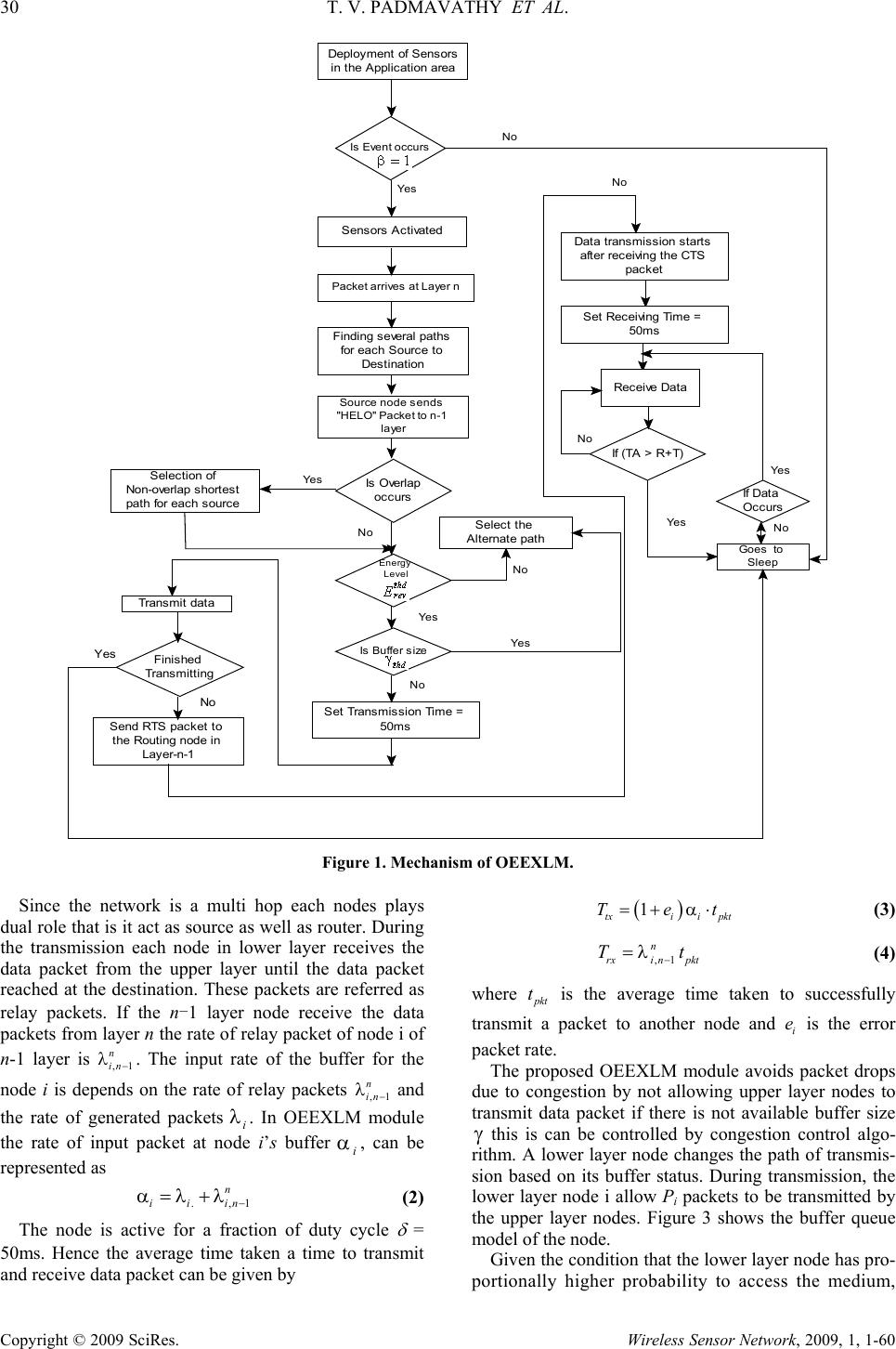 30 T. V. PADMAVATHY ET AL. Copyright © 2009 SciRes. Wireless Sensor Network, 2009, 1, 1-60 Is Event occurs Packet arrives at Layer n No Yes Finding several paths for each Source to Destination Selection of Non-overlap shortest path for each source Transmit data Finished Tran smittin g Deployment of Sensors in the Application area Sensors Activated If (TA > R+T) Set Transmission Time = 50m s Send RTS packet to the Routing node in Layer-n-1 If Data Oc curs Data transmission starts after receiving the CTS packet Set Receiving Time = 50ms Receive Data Is Buffer size Source node sends "HELO" Packet to n-1 layer Is Overlap occu rs No Ye s Select the Alternate path Yes No No Yes No No Goes to Sle ep Yes No Energy Level Yes Ye s No Figure 1. Mechanism of OEEXLM. Since the network is a multi hop each nodes plays dual role that is it act as source as well as router. During the transmission each node in lower layer receives the data packet from the upper layer until the data packet reached at the destination. These packets are referred as relay packets. If the n-1 layer node receive the data packets from layer n the rate of relay packet of node i of n-1 layer is ,1 n in− λ. The input rate of the buffer for the node i is depends on the rate of relay packets ,1 n in − λ and the rate of generated packets λ i. In OEEXLM module the rate of input packet at node i’s buffer αi, can be represented as .,1 n iiin− α=λ+λ (2) The node is active for a fraction of duty cycle δ = 50ms. Hence the average time taken a time to transmit and receive data packet can be given by ( ) 1 txii pkt Tet = +α⋅ (3) ,1 n rxi npkt Tt − =λ (4) where pkt t is the average time taken to successfully transmit a packet to another node and i e is the error packet rate. The proposed OEEXLM module avoids packet drops due to congestion by not allowing upper layer nodes to transmit data packet if there is not available buffer size γ this is can be controlled by congestion control algo- rithm. A lower layer node changes the path of transmis- sion based on its buffer status. During transmission, the lower layer node i allow Pi packets to be transmitted by the upper layer nodes. Figure 3 shows the buffer queue model of the node. Given the condition that the lower layer node has pro- portionally higher probability to access the medium,  T. V. PADMAVATHY ET AL. 31 Copyright © 2009 SciRes. Wireless Sensor Network, 2009, 1, 1-60 Source ID Type of Node Energy level 2 Byte 1 Byte 4 Byte Figure 2. HELLO message packet format. Figure 3. Buffer queue model. even then the lower layer node may not be able to for- ward all i P packets. So, in the next transmission, the lower layer node will have some packets from the previ- ous transmission, which might cause Congestion within few successive transmissions. Therefore, for each transmission upper layer nodes check the routing table if the buffer size γ less than the buffer threshold thd γ up- per layer node takes the alternate path. Maximum num- ber of packet hold by the buffer is buff N. The transmis- sion only occur when γ >thd γ thd γ =byff N≥0 in ii p = = ∑ (5) where buff l N= γ − γ . As a result of congestion control algorithm, the OE- EXLM module avoid the layer to layer congestion occur in the networks. Because of this energy consumed by the node is reduced there by improving the life time of the network. The medium control access scheme uses three algo- rithms to improve the energy efficiency and in network layer we use two algorithms to improve the life time of the networks. These two layers are integrated by using initiative conditions as per Equation (1). 5. Network Topology Figure 4 shows the data flow for the OEEXLM module. The nodes in the network operate in three different modes-sleeping, receiving and sending. Each node goes to sleep periodically to save energy and then wakes up and listens to see if any other node wants to talk to it. During sleep, the node turns off its radio; therefore the energy waste due to idle listening can be reduced. The nodes with same layer-count are given the same schedule, and the sending and receiving periods are staggered layer by layer such that when one node is in sending mode, its lower-layer node is in receiving mode. After receiving a message from an upper-layer node, each node can transmit it to the lower-layer node in the subsequent sending period. So a packet can be transmit- ted to sink nodes through multi-layers fleetly and the end-to-end latency is reduced. 5.1. Performance Evaluation The Table 1 shows the simulation setup used for simula- tion. 5.1.1. Latency Vs Network Area (MAC) Figure 5 infers that in S-MAC a node has to wait till its neighbouring node as to awake to transmit the message to it. This results there will be some amount of delay in S-MAC protocol, which is absent in OEEXLM module. In OEEXLM module whenever a node is in send state, the lower layer node is in receiving state. So the source node can transmit the message to the lower layer without checking whether the lower layer node is listening or sleeping mode. Hence the source node can transmit its message fleetly to the sink through multi layers. 5.1.2. Energy Consumption Vs Network Area (MAC) The Figure 6 infers that depicts the energy consumption of S-MAC and OEEXLM module. The comparison is made for a simulation setup with ten layers, ten nodes in each layer and a four sink. The graph shows that OE- EXLM module protocol uses less energy than S-MAC. This is because the idle listening dominates the energy consumption in S-MAC protocol but TA can make OE- EXLM module go to sleeping mode earlier, and the en- ergy consumption is reduced. The energy consumption of OEEXLM module is 35% -83% les than existing S- MAC protocol. 5.1.3. Latency Vs Number of Hop (MAC) The Figure 7 shows that the latency encountered in OE- EXLM module compared with that in S-MAC with respect to number of hops. Obviously the latency of OEEXLM Table 1. Simulation setup. Parameters Value Transmission Range 250 m Network Area 100 x 100 Number of Sensors 100- 1500 Packet rate 5 pkt/sec Packet size 512 bytes Radio Bandwidth 76kbps Transmitting Power 75mW (270J) Receiving Power 36mW (129.6J) Power Consumption in Sleep mode 100μ W (0.36 J) Sending and Receiving Slot 50msec Type of mote Mica2 Inital energy of sensor node 2KJ Energy Threshold Ethd 0.001mJ buff N l γ γ  32 T. V. PADMAVATHY ET AL. Copyright © 2009 SciRes. Wireless Sensor Network, 2009, 1, 1-60 Figure 4. Data flow diagram for OEEXLM module. Figure 5. Latency vs network area. module is lesser than that in the S-MAC because of staggered scheduling algorithm. In S-MAC a node has to wait till its neighbour is awake to transmit the message to it. This problem is not occurring in OEEXLM module. In OEEXLM module whenever a node is in send state, the lower layer node is in receiving state. So the source node can transmit the message to the lower layer without checking whether the lower layer node is listening. Hence the source node can transmit its message fleetly to the sink through multi layers. 5.1.4. Latency Vs Number of Hops (Routing) Figure 8 infers the delay as a function of the number of nodes in the WSN. The delay increases with the number of hops increasing. Our simulation shows the average delay of the proposed protocol is better than that of the directed diffusion. This is because in OEEXLM module, for each transmission each node in the routing checks the buffer condition, so that no queue of data occurs in the buffer. Due to alternate path algorithm the shortest delay oc- cur compared to other schemes. As we expected, data packets are routed through different node-with the help of proper design of algorithm in routing. Hence, the net- work congestion can be avoided. 5.1.5. Energy consumption Vs Number of Nodes (Routing) Figure 9 infers that energy consumption per node ver- sus number of nodes. The value of node energy con- sumption gives the average energy dissipated by the node in order to transmit the packet from source to drain. The same metric is used in [6] to determine the energy efficiency level of WSNs. It is calculated as follows: () 1 1 ,, N ii i S j j e initiale resi NodeEnergy Consumption NdataP = = − =∑ ∑ (6) where N is the total number of nodes, initialei, initial energy of nodes, resiei, is the residual energy of the nodes, S is the number of sinks and j P is the number of data packets received by the sink j. Figure 6. Energy consumption vs network area. Figure 7. Latency vs number of hops. Layer n Layer n-1 Layer 1 Sink  T. V. PADMAVATHY ET AL. 33 Copyright © 2009 SciRes. Wireless Sensor Network, 2009, 1, 1-60 Figure 8. Comparison of latency vs number of hops with DD. Figure 9. Energy consumption vs number of nodes. The simulation result infers that there is lower node energy consumption in CRLS protocol over the other schemes., The energy consumption of nodes in OE- EXLM module is 34% to 84% lesser than when com- pared with directed diffusion. This results shows that the energy efficiency of OEEXLM module is stable and has little impact by the increase of the network size, while the performance of other schemes degrades with larger network size. 5.1.6. Network Life Time The system lifetime is defined as the number of rounds for which 75% of the nodes are still alive. CRSL The transmitted and received energy costs for the transmis- sion of a k-bit data message between two nodes sepa- rated by a distance of r meters are given by Equations (6) and (7), respectively. () () ttxamp Ek,rEk Erk=+ (7) () rrx Ek Ek= (8) In Equation (7) )( r,kEt denotes the total energy dis- sipated in the transmitter of the source node, while () r Ek in Equation (8) represents the energy cost in- curred in the receiver of the destination node. Parame- ters tx E and rx E are per bit energy dissipation for transmission and reception, respectively, and )( rEamp denotes the energy required by the transmitted amplifier to maintain an acceptable radio for transferring data re- liably. The free-space propagation model is applied, and the transmit amplifier )(rEamp is given by Equation (9) 2 amp FS Er=ε (9) where e F S is the transmitted amplifier parameter. The set of parameter given in [7,8]. F S e =10 pJ/b/m2. From Figure 8, we infer that the network lifetime is increased by using the alternate path and congestion control algorithm. The network lifetime is given in terms of rounds till which 75% of nodes are alive. A network is assumed to be useless when one of the sensor’s en- ergy is below the threshold. 5.1.7. Data Packet Delivery Ratio Data packet delivery ratio can be calculated as the ratio between the number of data packets that are sent by the source and the number of data packets that are received by the sink. It can be denoted as R Successfully delivereddata Data Delivery RatioRequired data = (10) This parameter R indicates both efficient of the rout- ing protocol and the effort required to receive data. In the ideal scenario the ratio should be equal to 1. If the ratio falls significantly below the ideal ratio, then it could be an indication of some of the packet dropped because of faults in the protocol design. However, if the ratio is higher than the ideal ratio, then it is an indication that the sink receives a data packet more than once. It is not desirable because reception of duplicate packets consumes the more energy. The relative number of du- plicates received by the sink is also important because based on that number the sink, can possibly take an ap- propriate action to reduce the redundancy. Figure 11 shows the data packet delivery ratio of DD and OEEXLM modules. To eliminate packet loss we use a rate of 5 packets/second. It is found that the delivery ratio of the two protocols increase as the node density increases. When node density is high, there are more nodes available for data forwarding, and this increases the delivery ratio. Directed diffusion protocol offers less packet delivery rates, compared to OEEXLM module because it does not adapt well its behavior to network size increase. The OEEXLM module has maintained constant delivery rates throughout the simulated scenar- ios because the paths are selected based on the energy availability and buffer size.  34 T. V. PADMAVATHY ET AL. Copyright © 2009 SciRes. Wireless Sensor Network, 2009, 1, 1-60 Figure 10. Network lifetime. Figure 11. Packet delivery ratio vs number of nodes. Figure 12. Performance variations with respect to buffer size. 5.2. Performance Variations with Respect to Buffer Size Figure 12 shows the performance variations when the buffer size varies from 50 bytes to 300 bytes. When the buffer size is 50 bytes number of packets reached at the destination is minimum because of congestion but packet delay is minimum. When the buffer size 300 bytes the number of packets dropped is minimum due to large buffer and the average delay per packet increases due to the increased queuing delay. 5.2.1. Packet Loss with Respect Buffer Size Figure 13 infers that packet loss get reduced due to in- creasing buffer size. The number of packets dropped due to buffer overflow in the case of the OEEXLM module almost zero. This is because each time after receiving the packets from upper layer the buffer size is calculated and updated in the routing table. Depending on updated value the routing path algorithm send the HELLO mes- sage to the other nodes in the routing. 5.2.2. Packet Delay with Buffer Size Figure 14 shows Packet delay Vs buffer size. The graph infers that as the buffer size increases the average delay per packet increases due to the increased queuing delay. Figure 13. Packet loss vs buffer size. Figure 14. Packet delay vs buffer size.  T. V. PADMAVATHY ET AL. 35 Copyright © 2009 SciRes. Wireless Sensor Network, 2009, 1, 1-60 When the buffer size is 120 bytes, packet delay is only 4 second from source to destination. When the buffer size is 300 bytes length the delay is 12 seconds because of queuing delay. From this graph, we find that as the buffer size increases the packet delay also increases. But throughput is maximum because the packet drop is minimum by compromising the delay. 6. Conclusions and Future Work In this paper we presented the Cross-Layer Design to improve the performance of the wireless sensor net- works. This protocol design is used to give the direct interactions between the Network layer and the MAC layer. The traditional Network layer and MAC layer have been removed, thus simplifying the protocol stack. Simulation results that our proposed scheme has higher node energy efficiency, lower average delay and control overhead than the directed diffusion protocol and S- MAC protocol. The energy consumption of nodes in OEEXLM module is 34% to 84% lesser than when compared with directed diffusion. Further the network life time is 78% improved compared to DD protocol. In future we are going to extend the OEEXML design to Physical layer. 7. References [1] F. Akyildiz, W. Su, Y. Sankarasubramaniam, and E. Cayirci, “A survey on sensor networks,” IEEE Commu- nications Magazine, 40(8), pp. 102–114, August 2002. [2] O. Zhi-Wen, B. K. Shruthi, and S. K. Sang, “Medium access control for wireless sensor networks,” CS258- Advanced Communication Networks, San Jose State University, 2005. [3] C. Sungrae, K. Kanuri, C. Jin-Woong, L. Jang-Yeon, and S. D. June, “Dynamic energy efficient TDMA-based MAC protocol for wireless sensor networks,” Autonomic and Autonomous Systems and International Conference on Networking and Services, ICAS-ICNS, pp. 48, October 23-28, 2005. [4] I. Demirkol, C. Ersoy, and F. Alagöz, “MAC protocols for wireless sensor networks: A Survey,” IEEE Commu- nications Magazine, pp. 115-121, 2006. [5] S. Singh and C. S. Raghavendra, “PAMAS: Power aware multi-access protocol with signaling for ad hoc net- works,” ACM Computer Communications Review, 28(3), pp. 5-26, 1998. [6] W. R. Heinzelman, Chandrakasan and H. Balakrishnan, “Energy-efficient communication protocol for wireless microsensor networks,” Proceedings of 33rd IEEE An- nual Hawaii International Conference on Systems Sci- ences, Hawaii, 2000. [7] W. B. Heinzelman, A. P. Chandrakasan, and H. Balakrish- nan, “An application-specific protocol architecture for wireless microsensor networks,” IEEE Transactions on Wireless Communications, Vol. 1, 2002. [8] C. Intanagonwiwat, R. Govindan, and D. Estrin, “Di- rected diffusion: Ascalable and robust communication paradigm for sensor networks,” in Proceedings of ACM MobiCom’00, Boston, MA, USA, pp. 56-67, August 2000. [9] C. Suh, K. Young-Bae, and S. Dong-Min, “An energy efficient cross-layer MAC protocol for wireless sensor networks,” Graduate School of Information and Com- munication, Ajou University, Republic of Korea, APWeb 2006, LNCS 3842, pp. 410-419, 2006. [10] Bouabdellah, Kechar1ahmed, and Louazani, “Energy efficient cross-layer MAC protocol for wireless sensor networks,” Department of Computer Science, Faculty of Science, University of Oran Es-Senia, BP. 1524 Oran, Algeria, 2002. [11] W. Y. Ge, J. S. Zhang, and S. M. Shen “A cross-layer design approach to multicast in wireless networks,” IEEE Transactions on Wireless Communications, Vol. 6, pp. 1063-1071, March 2007. |