Paper Menu >>
Journal Menu >>
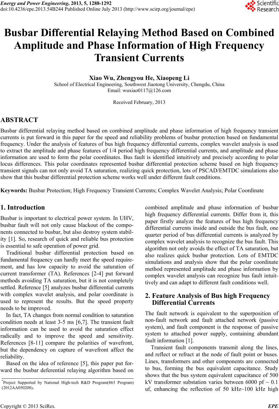 Energy and Power Engineering, 2013, 5, 1288-1292 doi:10.4236/epe.2013.54B244 Published Online July 2013 (http://www.scirp.org/journal/epe) Busbar Differential Relaying Method Based on Combined Amplitude and Phase Information of High Frequency Transient Currents Xiao Wu, Zhengyou He, Xiaopeng Li School of Electrical Engineering, Southwest Jiaotong University, Chengdu, China Email: wuxiao0117@126.com Received February, 2013 ABSTRACT Busbar differential relaying method based on combined amplitude and phase information of high frequency transient currents is put forward in this paper for the speed and reliability problems of busbar protection based on fundamental frequency. Under the analysis of features of bus high frequency differential currents, complex wavelet analysis is used to extract the amplitude and phase features of 1/4 period high frequency differential currents, and amplitude and phase information are used to form the polar coordinates. Bus fault is identified intuitively and precisely according to polar locus differences. This polar coordinates represented busbar differential protection scheme based on high frequency transient signals can not only avoid TA saturation, realizing quick protection, lots of PSCAD/EMTDC simulations also show that this busbar differential protection scheme works well under different fault conditions. Keywords: Busbar Protection; High Frequency Transient Currents; Complex Wavelet Analysis; Polar Coordinate 1. Introduction Busbar is important to electrical power system. In UHV, busbar fault will not only cause blackout of the compo- nents connected to busbar, but also destroy system stabil- ity [1]. So, research of quick and reliable bus protection is essential to safe operation of power grid. Traditional busbar differential protection based on fundamental frequency can hardly meet the speed require- ment, and has low capacity to avoid the saturation of current transformer (TA). References [2-4] put forward methods avoiding TA saturation, but it is not completely settled. Reference [5] analyzes busbar differential currents with complex wavelet analysis, and polar coordinate is used to represent the results. But the speed property needs to be improved. In fact, TA changes from normal condition to saturation condition needs at least 3-5 ms [6,7]. The transient fault information can be used to avoid the saturation effect radically and to improve the speed and sensitivity. References [8-11] compare the polarities of wavefront, but the dependency on capture of wavefront affect the reliability. Based on the idea of reference [5], this paper put for- ward the busbar deferential relaying algorithm based on combined amplitude and phase information of busbar high frequency differential currents. Differ from it, this paper firstly analyze the features of bus high frequency differential currents inside and outside the bus fault, one quarter period of bus differential currents is analyzed by complex wavelet analysis to recognize the bus fault. This algorithm not only avoids the effect of TA saturation, but also realizes quick busbar protection. Lots of EMTDC simulations and analysis show that the polar coordinate method represented amplitude and phase information by complex wavelet analysis can recognize bus fault intuit- tively and can adapt to different fault conditions well. 2. Feature Analysis of Bus high Frequency Differential Currents The fault network is equivalent to the superposition of non-fault network and fault attached network (passive system), and fault component is the response of passive system to attached power supply, containing abundant fault information [1]. Transient fault components transmit along the lines, and reflect or refract at the node of fault point or buses. Lines, transformers and other components are connected to bus, forming the bus equivalent capacitance. Study shows that the bus system equivalent capacitance of 500 kV transformer substation varies between 6000 pf ~ 0.1 uf, enhancing the reflection of 50 kHz~100 kHz high *Project Supported by National High-tech R&D Program(863 Program) (2012AA050208). Copyright © 2013 SciRes. EPE 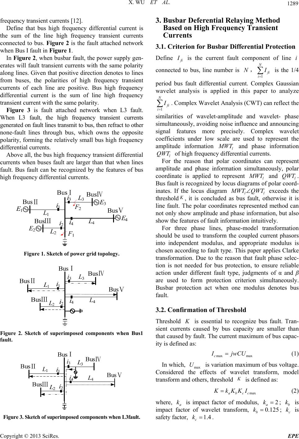 X. WU ET AL. 1289 frequency transient currents [12]. Define that bus high frequency differential current is the sum of the line high frequency transient currents connected to bus. Figure 2 is the fault attached network when Bus I fault in Figure 1. In Figure 2, when busbar fault, the power supply gen- erates will fault transient currents with the same polarity along lines. Given that positive direction denotes to lines from buses, the polarities of high frequency transient currents of each line are positive. Bus high frequency differential current is the sum of line high frequency transient current with the same polarity. Figure 3 is fault attached network when L3 fault. When L3 fault, the high frequency transient currents generated on fault lines transmit to bus, then refract to other none-fault lines through bus, which owns the opposite polarity, forming the relatively small bus high frequency differential currents. Above all, the bus high frequency transient differential currents when buses fault are larger than that when lines fault. Bus fault can be recognized by the features of bus high frequency differential currents. Figure 1. Sketch of power grid topology. Figure 2. Sketch of superimposed components when Bus1 fault. Figure 3. Sketch of superimposed components when L3fault. 3. Busbar Deferential Relaying Method Based on High Frequency Transient Currents 3.1. Criterion for Busbar Differential Protection Define f i I is the current fault component of line i connected to bus, line number is , N 1 N f i i I is the 1/4 period bus fault differential current. Complex Gaussian wavelet analysis is applied in this paper to analyze 1 N f i i I . Complex Wavelet Analysis (CWT) can reflect the similarities of wavelet-amplitude and wavelet- phase simultaneously, avoiding noise influence and announcing signal features more precisely. Complex wavelet coefficients under low scale are used to represent the amplitude information l M WT and phase information of high frequency differential currents. l For the reason that polar coordinates can represent amplitude and phase information simultaneously, polar coordinate is applied to represent l QWT M WT and l. Bus fault is recognized by locus diagrams of polar coord- inates. If the locus diagram ll QWT M WT QWT exceeds the threshold K , it is concluded as bus fault, otherwise it is line fault. The polar coordinates represented method can not only show amplitude and phase information, but also show the features of fault information intuitively. For three phase lines, phase-model transformation should be used to transform the coupled current phasors into independent modulus, and appropriate modulus is chosen according to fault type. This paper applies Clarke transformation. Due to the reason that fault phase selec- tion is not needed for bus protection, to ensure reliable action under different fault type, judgments of α and β are used to form protection criterion simultaneously. Busbar protection act when one modulus denotes bus fault. 3.2. Confirmation of Threshold Threshold is essential to recognize bus fault. Tran- sient currents caused by bus capacity are smaller than that caused by fault. The current maximum of bus capac- ity is defined as: K max maxc I jwCU (1) In which, max is variation maximum of bus voltage. Considered the effects of wavelet transform, model transform and others, threshold U K is defined as: maxabcc KkKKI (2) where, a is impact factor of modulus, k2 a k ; is impact factor of wavelet transform, ; is safety factor, b k c k0.125 b k 1.4 c k . Copyright © 2013 SciRes. EPE 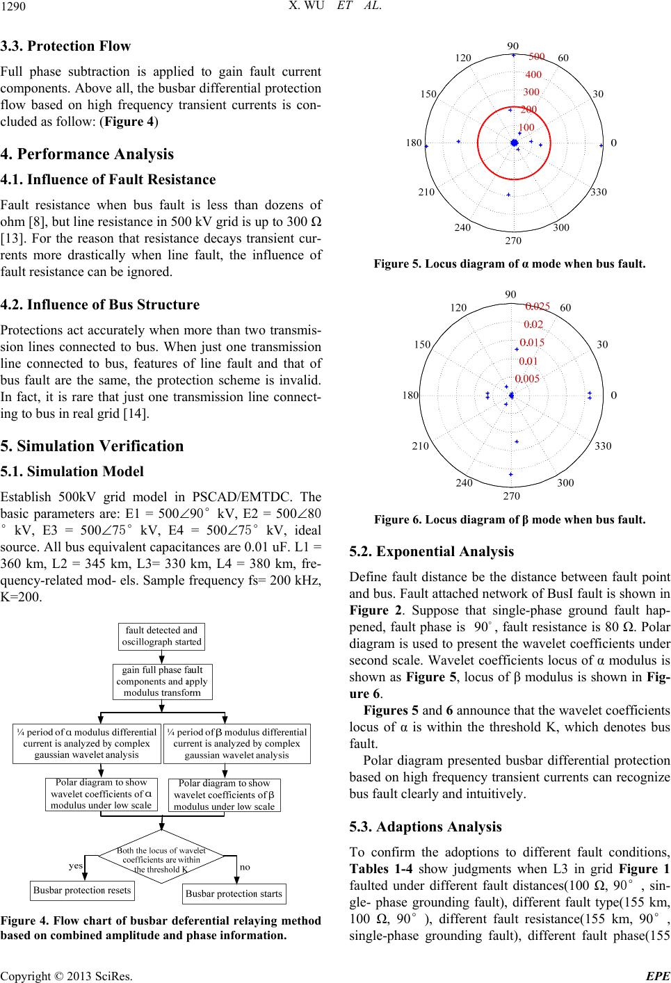 X. WU ET AL. 1290 3.3. Protection Flow Full phase subtraction is applied to gain fault current components. Above all, the busbar differential protection flow based on high frequency transient currents is con- cluded as follow: (Figure 4) 4. Performance Analysis 4.1. Influence of Fault Resistance Fault resistance when bus fault is less than dozens of ohm [8], but line resistance in 500 kV grid is up to 300 Ω [13]. For the reason that resistance decays transient cur- rents more drastically when line fault, the influence of fault resistance can be ignored. 4.2. Influence of Bus Structure Protections act accurately when more than two transmis- sion lines connected to bus. When just one transmission line connected to bus, features of line fault and that of bus fault are the same, the protection scheme is invalid. In fact, it is rare that just one transmission line connect- ing to bus in real grid [14]. 5. Simulation Verification 5.1. Simulation Model Establish 500kV grid model in PSCAD/EMTDC. The basic parameters are: E1 = 50090°kV, E2 = 50080 °kV, E3 = 50075°kV, E4 = 50075°kV, ideal source. All bus equivalent capacitances are 0.01 uF. L1 = 360 km, L2 = 345 km, L3= 330 km, L4 = 380 km, fre- quency-related mod- els. Sample frequency fs= 200 kHz, K=200. Figure 4. Flow chart of busbar deferential relaying method based on combined amplitude and phase information. Figure 5. Locus diagram of α mode when bus fault. Figure 6. Locus diagram of β mode when bus fault. 5.2. Exponential Analysis Define fault distance be the distance between fault point and bus. Fault attached network of BusI fault is shown in Figure 2. Suppose that single-phase ground fault hap- pened, fault phase is , fault resistance is 80 Ω. Polar diagram is used to present the wavelet coefficients under second scale. Wavelet coefficients locus of α modulus is shown as Figure 5, locus of β modulus is shown in Fig- ure 6. 90 Figures 5 and 6 announce that the wavelet coefficients locus of α is within the threshold K, which denotes bus fault. Polar diagram presented busbar differential protection based on high frequency transient currents can recognize bus fault clearly and intuitively. 5.3. Adaptions Analysis To confirm the adoptions to different fault conditions, Tables 1-4 show judgments when L3 in grid Figure 1 faulted under different fault distances(100 Ω, 90°, sin- gle- phase grounding fault), different fault type(155 km, 100 Ω, 90°), different fault resistance(155 km, 90°, single-phase grounding fault), different fault phase(155 Copyright © 2013 SciRes. EPE  X. WU ET AL. 1291 km, 100 Ω, single-phase grounding fault), Tables 5-7 show judg- ments when BusI faulted under different fault type(20 Ω, 90°), different fault resistance(90°, sin- gle-phase grounding fault), different fault phase(20 Ω, single-phase grounding fault). Concluded from the judg- ment results, the proposed busbar differential protection scheme adapts to different fault conditions well. Although the bus differential protection scheme based on high frequency transient currents is invalid under zero voltage fault, the probability of zero fault is so rare that the influence can be ignored. Table 1. Judgment for different distance on L3. Fault distance Maximum of α locus Maximum of β locus Judgment result 1 km 88.94 0.0213 lucoses of α and β within K line fault 75 km 69.01 0.0221 lucoses of α and β within K line fault 155 km 45.35 0.0224 lucoses of α and β within K line fault 255 km 38.57 0.02236 lucoses of α and β within K line fault 329 km 23.13 0.0216 lucoses of α and β within K line fault Table 2. Judgment for different fault type on L3. Fault type Maximum of α locus Maximum of β locus Judgment result Ag 45.35 0.0224 lucoses of α and β within K line fault BCg 20.82 12.53 lucoses of α and β within K line fault BC 0.0097 15.11 lucoses of α and β within K line fault ABC 96.73 16.23 lucoses of α and β within K line fault ABCg 74.7 12.53 lucoses of α and β within K line fault Table 3. Judgment for different fault resistance on L3. Fault resistance Maximum of α locus Maximum of β locus Judgment result 0 Ω 65.84 0.0224 lucoses of α and β within K line fault 50 Ω 53.71 0.0224 lucoses of α and β within K line fault 120 Ω 42.7 0.0223 lucoses of α and β within K line fault 220 Ω 33.02 0.0223 lucoses of α and β within K line fault 300 Ω 27.95 0.0223 lucoses of α and β within K line fault Table 4. Judgment for different fault phase on L3. Fault phase Maximum of α locus Maximum of β locusjudgment result 90°45.35 0.0224 lucoses of α and β within K line fault 60°40.81 0.0224 lucoses of α and β within K line fault 30°26.69 0.0223 lucoses of α and β within K line fault 0°0.01 0.0223 lucoses of α and β within K line fault Table 5. Judgment for different fault type on BusⅠ. Fault type Maximum of α locus Maximum of β locusjudgment result Ag 796.8 0.0224 lucos of α exceeds K busbar fault BCg324.8 7626 locuses of α and β exceed K bus fault BC 0.0097 8778 locuses of α and β exceed K bus fault ABC3020 9233 locuses of α and β exceed K bus fault Table 6. Judgment for different fault resistance on Bus I. Fault resistance Maximum of α locus Maximum of β locus Judgment result 0Ω 1209 0.0224 lucos of α exceeds K busbar fault 20Ω 796.8 0.0224 lucos of α exceeds K busbar fault 40Ω 622.7 0.0224 lucos of α exceeds K busbar fault 60Ω 547.6 0.0224 lucos of α exceeds K busbar fault 80Ω 489.8 0.0224 lucos of α exceeds K busbar fault Table 7. Judgment for different fault phase on Bus I. Fault phase Maximum of α locus Maximum of β locusjudgment result 90°796.8 0.0224 lucos of α exceeds K busbar fault 60°622.6 0.0224 lucos of α exceeds K busbar fault 30°330.4 0.0224 lucos of α exceeds K busbar fault 0°0.0103 0.0224 both locuses of α and β within K line fault 6. Conclusions Bus differential protection scheme based on the features of bus high frequency differential currents is put forward in this paper, conclusions are summarized as following: 1) High frequency differential currents when bus fault are larger than that when line fault. 2) Complex wavelet analysis can avoid noise influence, extracting amplitude and phase features more precisely; Copyright © 2013 SciRes. EPE  X. WU ET AL. Copyright © 2013 SciRes. EPE 1292 Polar presented protection scheme can recognize bus fault more intuitively. 3) Bus differential protection scheme combined am- plitude and phase information is not affected by TA sa- turation, realizing quick protection. EMTP simulations show that this protection scheme adapts to different fault conditions well. REFERENCES [1] Y. Z. Ge, “New Protective Relay and Fault Location Prin- ciple and Technique, Xi;an: Xi’an Jiaotong University Press, 2007. [2] Y. B. Zhao and Y. P. Lu, “An Asynchronous Method Based Saturation Criterion for CT in Busbar Protection,” Power System Technology, Vol. 30, No. 6, 2006, pp. 6-90. [3] J. F. Ren and G. Li, “Study on an Integrated Criterion for Ta Anti-saturation of Microprocessor-based Busbar Dif- ferential Protection,” Power System Technology, Vol. S2, 2006, pp. 362-366. [4] C. H. Wu, Y. P. Lu and X. B. Liu, “Busbar Sampled Value Differential Protection Based on Linear Transfer Section Checking of TA, Power System Technology, Vol. 32, No. 14, 2008, pp. 71-74. [5] M. M. Eissa, “A New Digital Busbar Protection Technique Based on Frequency Information during CT Saturation,” Electrical Power and Energy Systems, 2013, pp. 42-49. [6] L. A. Kojovie, “Guidelines for Current Transformers Se- lection for Protection Systems,” IEE Power Engineering Society Summer Meeting, 2001, pp. 593-598. [7] Y. D. Liu, Z. P. Wang and Z. M. Zhang, “Study on Com- prehensive TA Saturation Criterion for Transformer Dif- ferential Protection,” Power System Technology, Vol. 31, No. 18, 2007, pp. 87-90. [8] Y. Z. Ge, X. L. Dong, et al., “A New Busbar Protectilon Based on Current Traveling Waves and Wavelet Trans- form - Principle and Criterion,” Transactions of CES, Vol. 18, No. 2, 2003, pp. 95-99. [9] J. D. Duan, B. H. Zhang et al., “A Distributed Bus Protec- tion Using Transient Traveling Wave Power Directions of Transmission Lines,” Proceedings of the CSEE, Vol. 24, No. 6, 2004, pp. 7-12. [10] J. Zhang, X. D. Zhang and T. Lin, “A Directional Protec- tion Based on Traveling Wave Current Polarity Com- parison Using Wavelet Transform,” Power System Tech- nology, Vol. 28, No. 4, 2004, pp. 51-54. [11] L. Cui, Q. Chao and L. F. Cui, “Research on Bus Travel- ling wave Protection Based on Wavelet Transform,” Elec- tric Switchgear, Vol. 1, 2009, pp. 53-55. [12] J. D. Duan, B. H. Zhang, J. F. Ren, et al., “Single-Ended Transient-based Protection for EHV Transmission Lines Basic Theory,” Proceedings of the CSEE, Vol. 27, No. 1, 2007, pp. 37-43. [13] B. H. Zhang and X. G. Yin, “New Relay Protection for Power Grid,” Beijing: Chine Electric Power Press, 2005 [14] H. F. Li, G. Wang et al., “A Novel Busbar Proteetion Based on Transient Current Spectrum Energy,” Automa- tion of Electric Power Systems, Vol. 29, No. 6, 2005, pp. 51-54. |