Paper Menu >>
Journal Menu >>
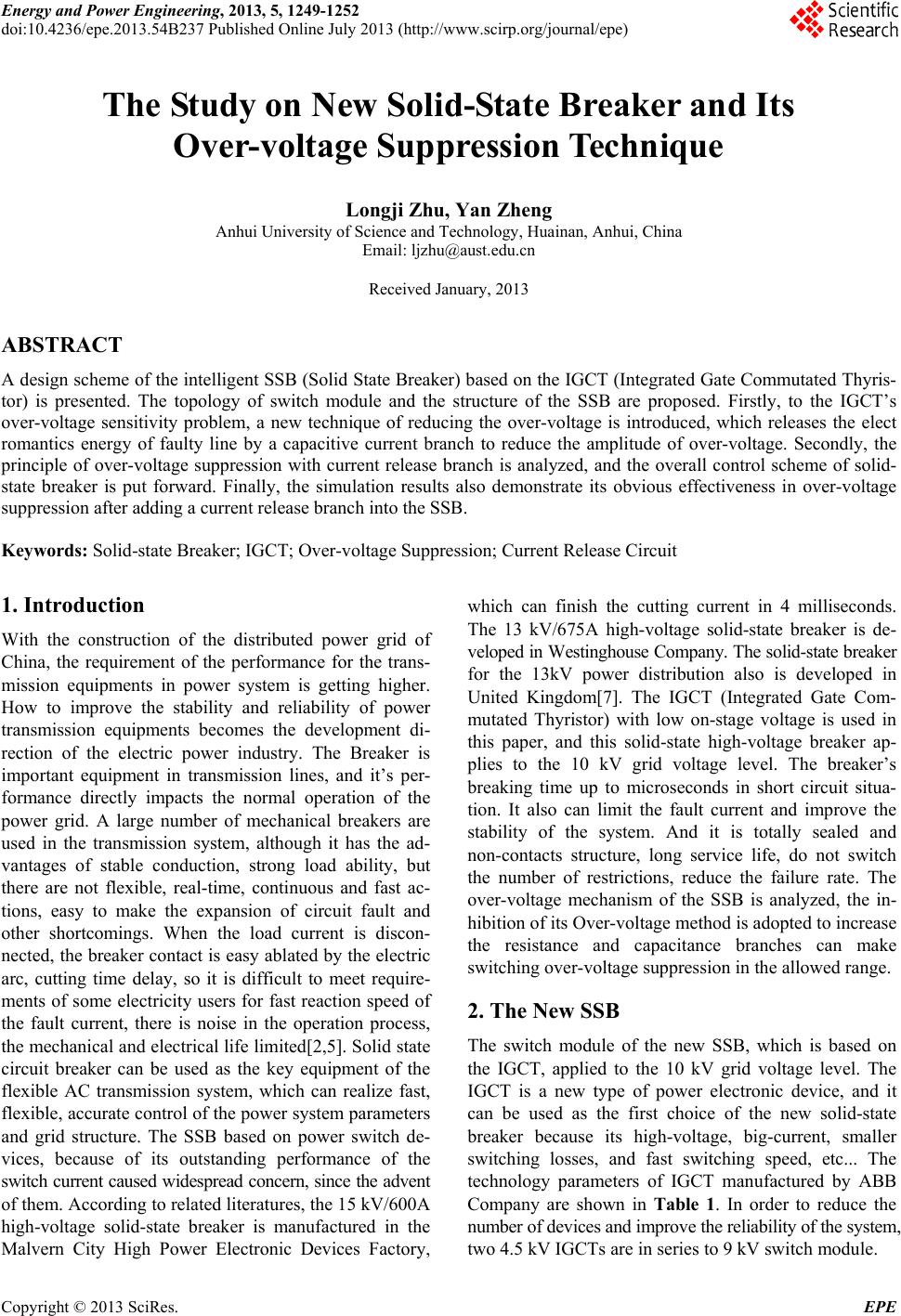 Energy and Power Engineering, 2013, 5, 1249-1252 doi:10.4236/epe.2013.54B237 Published Online July 2013 (http://www.scirp.org/journal/epe) The Study on New Solid-State Breaker and Its Over-voltage Suppression Technique Longji Zhu, Yan Zheng Anhui University of Science and Technology, Huainan, Anhui, China Email: ljzhu@aust.edu.cn Received January, 2013 ABSTRACT A design scheme of the intelligent SSB (Solid State Breaker) based on the IGCT (Integrated Gate Commutated Thyris- tor) is presented. The topology of switch module and the structure of the SSB are proposed. Firstly, to the IGCT’s over-voltage sensitivity problem, a new technique of reducing the over-voltage is introduced, which releases the elect romantics energy of faulty line by a capacitive current branch to reduce the amplitude of over-voltage. Secondly, the principle of over-voltage suppression with current release branch is analyzed, and the overall control scheme of solid- state breaker is put forward. Finally, the simulation results also demonstrate its obvious effectiveness in over-voltage suppression after adding a current release branch into the SSB. Keywords: Solid-state Breaker; IGCT; Over-voltage Suppression; Current Release Circuit 1. Introduction With the construction of the distributed power grid of China, the requirement of the performance for the trans- mission equipments in power system is getting higher. How to improve the stability and reliability of power transmission equipments becomes the development di- rection of the electric power industry. The Breaker is important equipment in transmission lines, and it’s per- formance directly impacts the normal operation of the power grid. A large number of mechanical breakers are used in the transmission system, although it has the ad- vantages of stable conduction, strong load ability, but there are not flexible, real-time, continuous and fast ac- tions, easy to make the expansion of circuit fault and other shortcomings. When the load current is discon- nected, the breaker contact is easy ablated by the electric arc, cutting time delay, so it is difficult to meet require- ments of some electricity users for fast reaction speed of the fault current, there is noise in the operation process, the mechanical and electrical life limited[2,5]. Solid state circuit breaker can be used as the key equipment of the flexible AC transmission system, which can realize fast, flexible, accurate control of the power system parameters and grid structure. The SSB based on power switch de- vices, because of its outstanding performance of the switch current caused widespread concern, since the advent of them. According to related literatures, the 15 kV/600A high-voltage solid-state breaker is manufactured in the Malvern City High Power Electronic Devices Factory, which can finish the cutting current in 4 milliseconds. The 13 kV/675A high-voltage solid-state breaker is de- veloped in Westinghouse Company. The solid-state breaker for the 13kV power distribution also is developed in United Kingdom[7]. The IGCT (Integrated Gate Com- mutated Thyristor) with low on-stage voltage is used in this paper, and this solid-state high-voltage breaker ap- plies to the 10 kV grid voltage level. The breaker’s breaking time up to microseconds in short circuit situa- tion. It also can limit the fault current and improve the stability of the system. And it is totally sealed and non-contacts structure, long service life, do not switch the number of restrictions, reduce the failure rate. The over-voltage mechanism of the SSB is analyzed, the in- hibition of its Over-voltage method is adopted to increase the resistance and capacitance branches can make switching over-voltage suppression in the allowed range. 2. The New SSB The switch module of the new SSB, which is based on the IGCT, applied to the 10 kV grid voltage level. The IGCT is a new type of power electronic device, and it can be used as the first choice of the new solid-state breaker because its high-voltage, big-current, smaller switching losses, and fast switching speed, etc... The technology parameters of IGCT manufactured by ABB Company are shown in Table 1. In order to reduce the number of devices and improve the reliability of the system, two 4.5 kV IGCTs are in series to 9 kV switch module. Copyright © 2013 SciRes. EPE 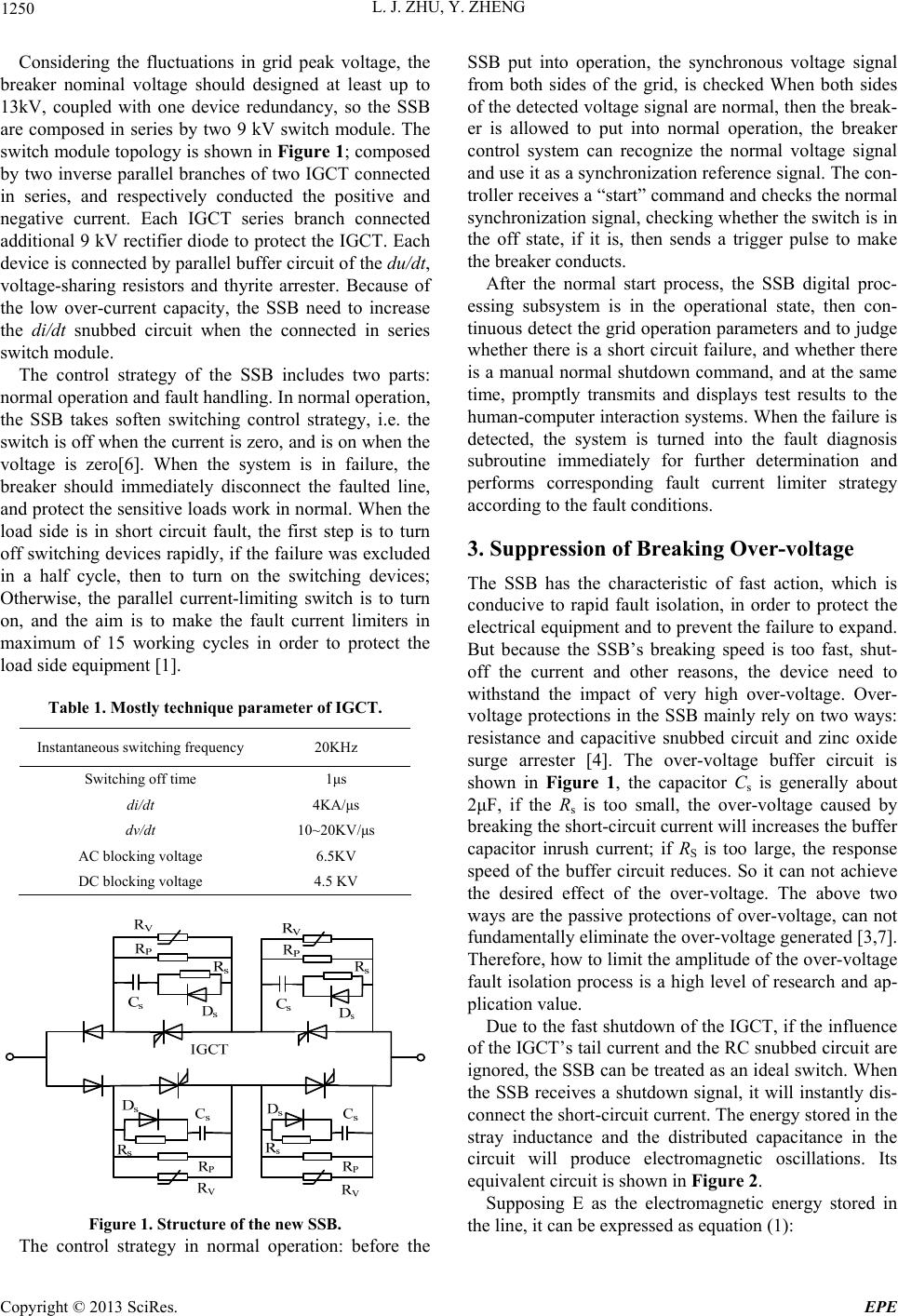 L. J. ZHU, Y. ZHENG 1250 Considering the fluctuations in grid peak voltage, the breaker nominal voltage should designed at least up to 13kV, coupled with one device redundancy, so the SSB are composed in series by two 9 kV switch module. The switch module topology is shown in Figure 1; composed by two inverse parallel branches of two IGCT connected in series, and respectively conducted the positive and negative current. Each IGCT series branch connected additional 9 kV rectifier diode to protect the IGCT. Each device is connected by parallel buffer circuit of the du/dt, voltage-sharing resistors and thyrite arrester. Because of the low over-current capacity, the SSB need to increase the di/dt snubbed circuit when the connected in series switch module. The control strategy of the SSB includes two parts: normal operation and fault handling. In normal operation, the SSB takes soften switching control strategy, i.e. the switch is off when the current is zero, and is on when the voltage is zero[6]. When the system is in failure, the breaker should immediately disconnect the faulted line, and protect the sensitive loads work in normal. When the load side is in short circuit fault, the first step is to turn off switching devices rapidly, if the failure was excluded in a half cycle, then to turn on the switching devices; Otherwise, the parallel current-limiting switch is to turn on, and the aim is to make the fault current limiters in maximum of 15 working cycles in order to protect the load side equipment [1]. Table 1. Mostly technique parameter of IGCT. Instantaneous switching frequency 20KHz Switching off time 1μs di/dt 4KA/μs dv/dt 10~20KV/μs AC blocking voltage 6.5KV DC blocking voltage 4.5 KV Figure 1. Structure of the new SSB. The control strategy in normal operation: before the SSB put into operation, the synchronous voltage signal from both sides of the grid, is checked When both sides of the detected voltage signal are normal, then the break- er is allowed to put into normal operation, the breaker control system can recognize the normal voltage signal and use it as a synchronization reference signal. The con- troller receives a “start” command and checks the normal synchronization signal, checking whether the switch is in the off state, if it is, then sends a trigger pulse to make the breaker conducts. After the normal start process, the SSB digital proc- essing subsystem is in the operational state, then con- tinuous detect the grid operation parameters and to judge whether there is a short circuit failure, and whether there is a manual normal shutdown command, and at the same time, promptly transmits and displays test results to the human-computer interaction systems. When the failure is detected, the system is turned into the fault diagnosis subroutine immediately for further determination and performs corresponding fault current limiter strategy according to the fault conditions. 3. Suppression of Breaking Over-voltage The SSB has the characteristic of fast action, which is conducive to rapid fault isolation, in order to protect the electrical equipment and to prevent the failure to expand. But because the SSB’s breaking speed is too fast, shut- off the current and other reasons, the device need to withstand the impact of very high over-voltage. Over- voltage protections in the SSB mainly rely on two ways: resistance and capacitive snubbed circuit and zinc oxide surge arrester [4]. The over-voltage buffer circuit is shown in Figure 1, the capacitor Cs is generally about 2μF, if the Rs is too small, the over-voltage caused by breaking the short-circuit current will increases the buffer capacitor inrush current; if RS is too large, the response speed of the buffer circuit reduces. So it can not achieve the desired effect of the over-voltage. The above two ways are the passive protections of over-voltage, can not fundamentally eliminate the over-voltage generated [3,7]. Therefore, how to limit the amplitude of the over-voltage fault isolation process is a high level of research and ap- plication value. Due to the fast shutdown of the IGCT, if the influence of the IGCT’s tail current and the RC snubbed circuit are ignored, the SSB can be treated as an ideal switch. When the SSB receives a shutdown signal, it will instantly dis- connect the short-circuit current. The energy stored in the stray inductance and the distributed capacitance in the circuit will produce electromagnetic oscillations. Its equivalent circuit is shown in Figure 2. Supposing E as the electromagnetic energy stored in the line, it can be expressed as equation (1): Copyright © 2013 SciRes. EPE 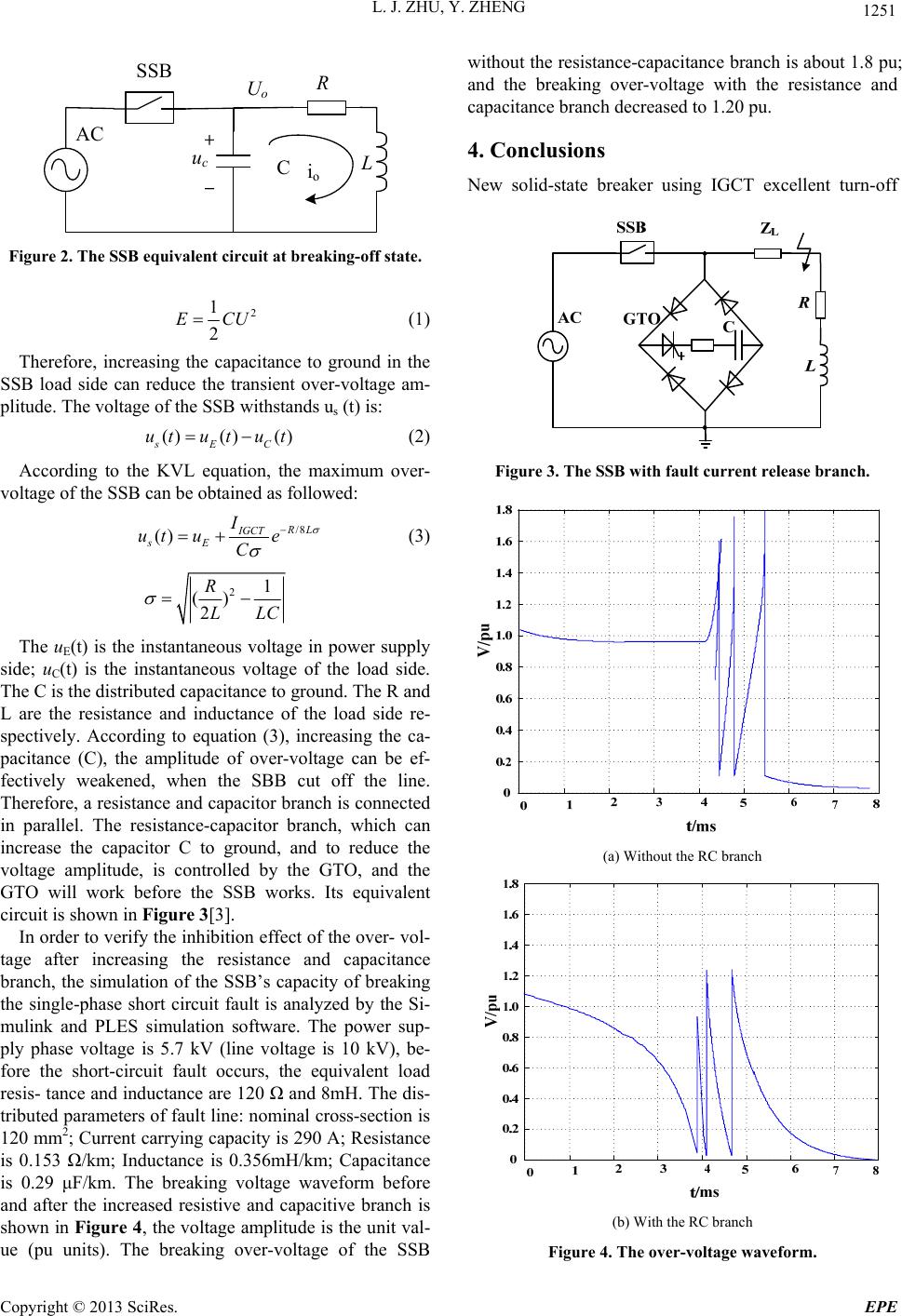 L. J. ZHU, Y. ZHENG 1251 SSB AC C ucL R Uo io Figure 2. The SSB equivalent circuit at breaking-off state. 2 1 2 ECU (1) Therefore, increasing the capacitance to ground in the SSB load side can reduce the transient over-voltage am- plitude. The voltage of the SSB withstands us (t) is: ()() () sEC utu tu t (2) According to the KVL equation, the maximum over- voltage of the SSB can be obtained as followed: /8 () R L IGCT sE I ut ue C (3) 21 () 2 R LLC The uE(t) is the instantaneous voltage in power supply side; uC(t) is the instantaneous voltage of the load side. The C is the distributed capacitance to ground. The R and L are the resistance and inductance of the load side re- spectively. According to equation (3), increasing the ca- pacitance (C), the amplitude of over-voltage can be ef- fectively weakened, when the SBB cut off the line. Therefore, a resistance and capacitor branch is connected in parallel. The resistance-capacitor branch, which can increase the capacitor C to ground, and to reduce the voltage amplitude, is controlled by the GTO, and the GTO will work before the SSB works. Its equivalent circuit is shown in Figure 3[3]. In order to verify the inhibition effect of the over- vol- tage after increasing the resistance and capacitance branch, the simulation of the SSB’s capacity of breaking the single-phase short circuit fault is analyzed by the Si- mulink and PLES simulation software. The power sup- ply phase voltage is 5.7 kV (line voltage is 10 kV), be- fore the short-circuit fault occurs, the equivalent load resis- tance and inductance are 120 Ω and 8mH. The dis- tributed parameters of fault line: nominal cross-section is 120 mm2; Current carrying capacity is 290 A; Resistance is 0.153 Ω/km; Inductance is 0.356mH/km; Capacitance is 0.29 μF/km. The breaking voltage waveform before and after the increased resistive and capacitive branch is shown in Figure 4, the voltage amplitude is the unit val- ue (pu units). The breaking over-voltage of the SSB without the resistance-capacitance branch is about 1.8 pu; and the breaking over-voltage with the resistance and capacitance branch decreased to 1.20 pu. 4. Conclusions New solid-state breaker using IGCT excellent turn-off Figure 3. The SSB with fault current release branch. (a) Without the RC branch (b) With the RC branch Figure 4. The over-voltage waveform. Copyright © 2013 SciRes. EPE 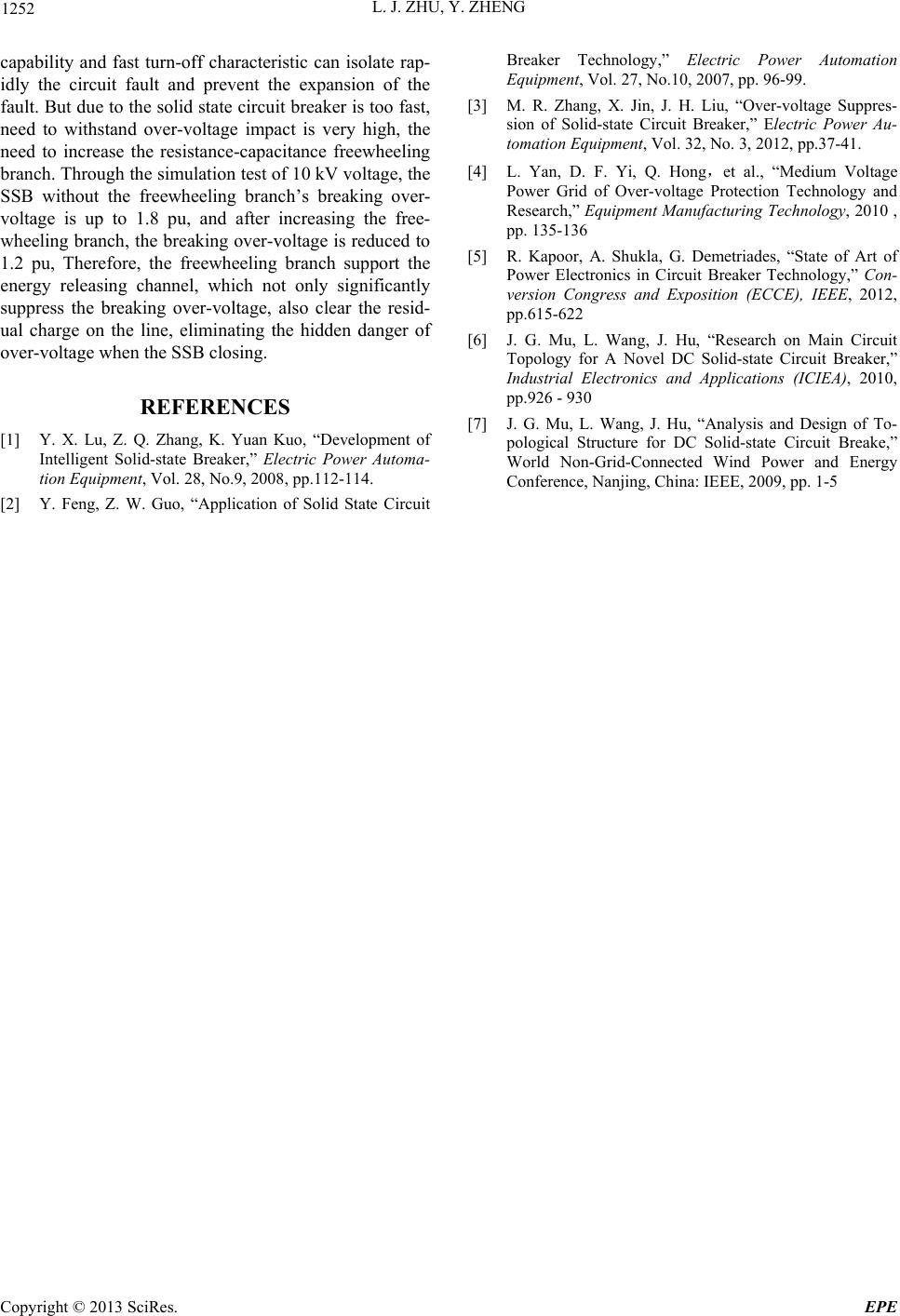 L. J. ZHU, Y. ZHENG Copyright © 2013 SciRes. EPE 1252 capability and fast turn-off characteristic can isolate rap- idly the circuit fault and prevent the expansion of the fault. But due to the solid state circuit breaker is too fast, need to withstand over-voltage impact is very high, the need to increase the resistance-capacitance freewheeling branch. Through the simulation test of 10 kV voltage, the SSB without the freewheeling branch’s breaking over- voltage is up to 1.8 pu, and after increasing the free- wheeling branch, the breaking over-voltage is reduced to 1.2 pu, Therefore, the freewheeling branch support the energy releasing channel, which not only significantly suppress the breaking over-voltage, also clear the resid- ual charge on the line, eliminating the hidden danger of over-voltage when the SSB closing. REFERENCES [1] Y. X. Lu, Z. Q. Zhang, K. Yuan Kuo, “Development of Intelligent Solid-state Breaker,” Electric Power Automa- tion Equipment, Vol. 28, No.9, 2008, pp.112-114. [2] Y. Feng, Z. W. Guo, “Application of Solid State Circuit Breaker Technology,” Electric Power Automation Equipment, Vol. 27, No.10, 2007, pp. 96-99. [3] M. R. Zhang, X. Jin, J. H. Liu, “Over-voltage Suppres- sion of Solid-state Circuit Breaker,” Electric Power Au- tomation Equi pment, Vol. 32, No. 3, 2012, pp.37-41. [4] L. Yan, D. F. Yi, Q. Hong,et al., “Medium Voltage Power Grid of Over-voltage Protection Technology and Research,” Equipment Manufacturing Technology, 2010 , pp. 135-136 [5] R. Kapoor, A. Shukla, G. Demetriades, “State of Art of Power Electronics in Circuit Breaker Technology,” Con- version Congress and Exposition (ECCE), IEEE, 2012, pp.615-622 [6] J. G. Mu, L. Wang, J. Hu, “Research on Main Circuit Topology for A Novel DC Solid-state Circuit Breaker,” Industrial Electronics and Applications (ICIEA), 2010, pp.926 - 930 [7] J. G. Mu, L. Wang, J. Hu, “Analysis and Design of To- pological Structure for DC Solid-state Circuit Breake,” World Non-Grid-Connected Wind Power and Energy Conference, Nanjing, China: IEEE, 2009, pp. 1-5 |