Paper Menu >>
Journal Menu >>
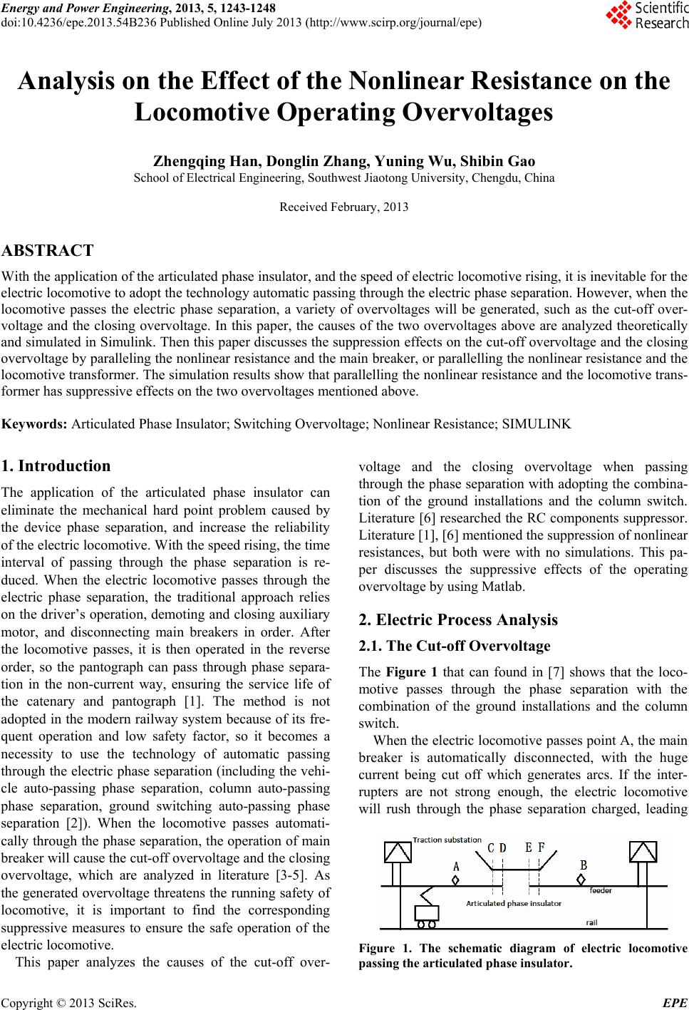 Energy and Power Engineering, 2013, 5, 1243-1248 doi:10.4236/epe.2013.54B236 Published Online July 2013 (http://www.scirp.org/journal/epe) Analysis on the Effect of the Nonlinear Resistance on the Locomotive Operating Overvoltages Zhengqing Han, Donglin Zhang, Yuning Wu, Shibin Gao School of Electrical Engineering, Southwest Jiaotong University, Chengdu, China Received February, 2013 ABSTRACT With the application of the articulated phase in sulator, and the speed of electric locomotive rising, it is inev itable for the electric locomotive to adop t the technolog y automatic passing through the electric phase separation. However, when the locomotive passes the electric phase separation, a variety of overvoltages will be generated, such as the cut-off over- voltage and the closing overvoltage. In this paper, the causes of the two overvoltages above are analyzed theoretically and simulated in Simulink. Then this paper discusses the suppression effects on the cut-off overvoltage and the closing overvoltage by paralleling th e nonlinear resistance and the main breaker, or parallelling the nonlin ear resistance an d the locomotive transformer. The simulation resu lts show that parallelling the no nlinear resistance and the locomotive trans- former has suppressive effects on the two overvo ltages mentioned above. Keywords: Articulated Phase Insulator; Switching Overvoltage; Nonlinear Resistance; SIMULINK 1. Introduction The application of the articulated phase insulator can eliminate the mechanical hard point problem caused by the device phase separation, and increase the reliability of the electric locomotive. With the speed rising, the time interval of passing through the phase separation is re- duced. When the electric locomotive passes through the electric phase separation, the traditional approach relies on the driver’s operation, demoting and closing auxiliary motor, and disconnecting main breakers in order. After the locomotive passes, it is then operated in the reverse order, so the pantograph can pass through phase separa- tion in the non-current way, ensuring the service life of the catenary and pantograph [1]. The method is not adopted in the modern railway system because of its fre- quent operation and low safety factor, so it becomes a necessity to use the technology of automatic passing through the electric ph ase separation (including the vehi- cle auto-passing phase separation, column auto-passing phase separation, ground switching auto-passing phase separation [2]). When the locomotive passes automati- cally through the ph ase separation, the operation of main breaker will cause th e cut-off overvo ltage and the clos ing overvoltage, which are analyzed in literature [3-5]. As the generated overvoltage threatens the running safety of locomotive, it is important to find the corresponding suppressive measures to ensure the safe operation of the electric locomotive. This paper analyzes the causes of the cut-off over- voltage and the closing overvoltage when passing through the phase separation with adopting the combina- tion of the ground installations and the column switch. Literature [6] researched the RC components suppressor. Literature [1], [6] mentioned th e suppression of no nlinear resistances, but both were with no simulations. This pa- per discusses the suppressive effects of the operating overvoltage by using Matlab. 2. Electric Process Analysis 2.1. The Cut-off Overvoltage The Figure 1 that can found in [7] shows that the loco- motive passes through the phase separation with the combination of the ground installations and the column switch. When the electric locomotive passes point A, the main breaker is automatically disconnected, with the huge current being cut off which generates arcs. If the inter- rupters are not strong enough, the electric locomotive will rush through the phase separation charged, leading Figure 1. The schematic diagram of electric locomotive passing the articulated phase insulator. Copyright © 2013 SciRes. EPE 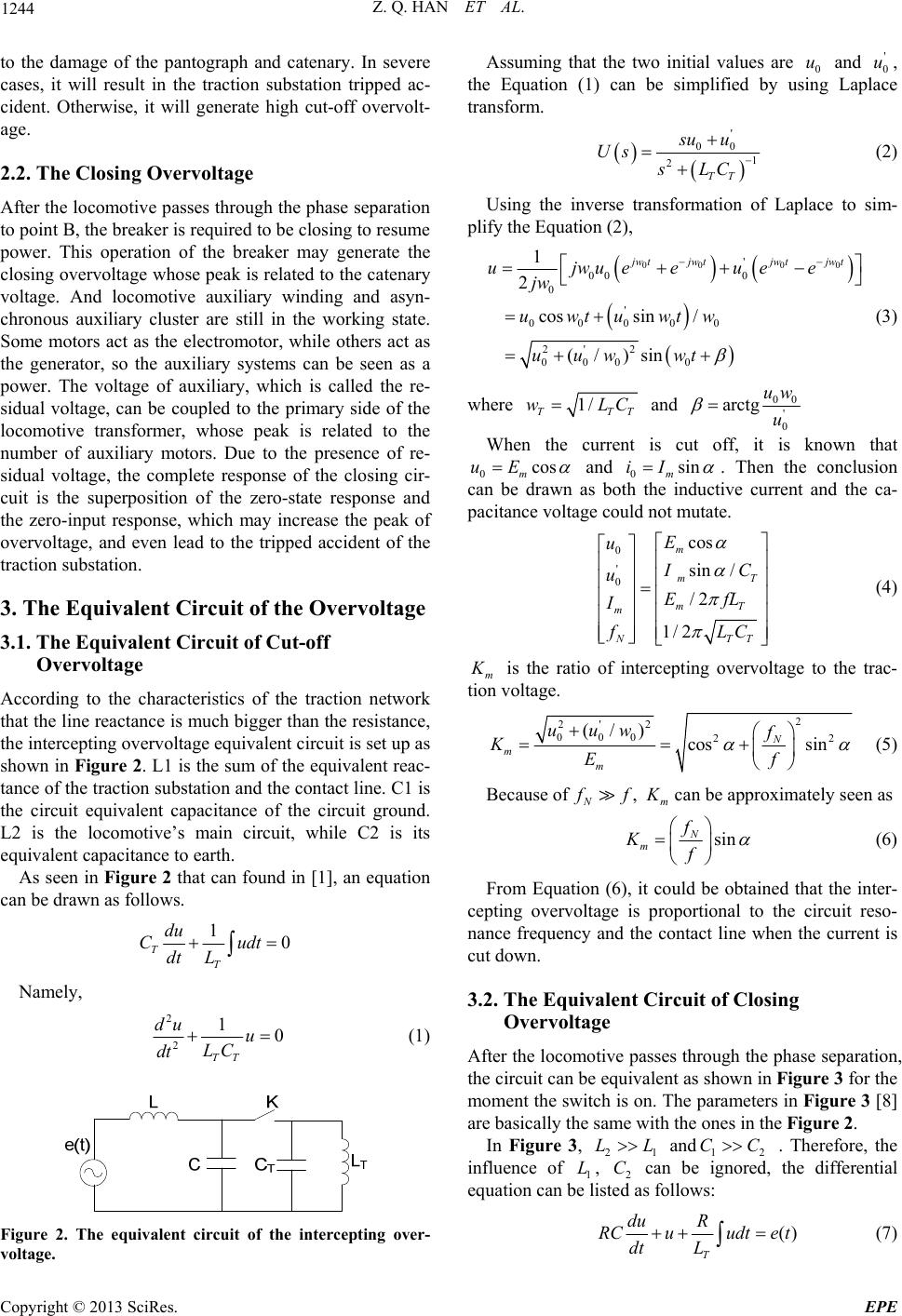 Z. Q. HAN ET AL. 1244 to the damage of the pantograph and catenary. In severe 2.2. The Closing Overvoltage the phase separation According to tracteristics of the traction network und in [1], an equation ca cases, it will result in the traction substation tripped ac- cident. Otherwise, it will generate high cut-off overvolt- age. After the locomotive passes through to point B, the breaker is required to be closing to resume power. This operation of the breaker may generate the closing overvoltage whose peak is related to the catenary voltage. And locomotive auxiliary winding and asyn- chronous auxiliary cluster are still in the working state. Some motors act as the electromotor, while others act as the generator, so the auxiliary systems can be seen as a power. The voltage of auxiliary, which is called the re- sidual voltage, can be coupled to the primary side of the locomotive transformer, whose peak is related to the number of auxiliary motors. Due to the presence of re- sidual voltage, the complete response of the closing cir- cuit is the superposition of the zero-state response and the zero-input response, which may increase the peak of overvoltage, and even lead to the tripped accident of the traction substation. 3. The Equivalent Circuit of the Overvoltage 3.1. The Equivalent Circuit of Cut-off Overvoltage he cha that the line reactance is much bigger than the resistance, the intercepting overvo ltag e equivalent circu it is set up as shown in Figure 2. L1 is the sum of the equivalent reac- tance of the traction substatio n and the con tact line. C1 is the circuit equivalent capacitance of the circuit ground. L2 is the locomotive’s main circuit, while C2 is its equivalent capacitance to earth. As seen in Figure 2 that can fo n be drawn as foll ows . 10 TT du C udt dt L Namely, 2 2 10 TT du u LC dt (1) Assuming that the two initial values are 0 u and ' 0 u, the Equation (1) can be simplified by using Laplace transform. ' su u 00 1 2TT Us sL C (2) Using the inverse transformation of La pli place to sim- fy the Equation (2), Figure 2. The equivalent circuit of the intercepti over- voltage. ng 00 00 ' 0 0 ' 00000 2' 2 000 0 cos sin / (/)sin tjw tjw tjw t euee uwtuwtw uuw wt 00 1 2 jw ujwue jw (3) where 1/ TT wLT C and 00 ' 0 arctg uw u Whe is cun the currentt off, it is known that 0mcosuE and 0msiniI . Then the conclusion pacitance voltld not muta t can be drawn as both the inductive current and the ca- age coue. 0cos m E u ' 0sin / /2 1/2 mT mT m NT T I C uEfL I fLC (4) m K tion vol is the ratio of intercepting overvoltage to the trac- tage. 2 2 0 u K'2 00 22 (/) cos sin N mm uw f Ef (5) Because of , N f f m K can be approximately seen as sin N m f Kf (6) From Equation (6), it could be obt cep quivalent Circuit of Closing paration, ained that the inter- ting overvoltage is proportional to the circuit reso- nance frequency and the contact line when the current is cut down. 3.2. The E Overvoltage After the locomotive passes through the phase se the circuit can be equivalent as shown in Figure 3 for the moment the switch is on. The p arameters in Figure 3 [8] are basically the same with the ones in the Fi g ure 2. In Figure 3, 21 LL and12 CC . Therefore, the influence of L, C can be ignored, the differen 1tial equation can be lisollows: 2 ted as f () T du R RC u dt L udte t (7) Copyright © 2013 SciRes. EPE 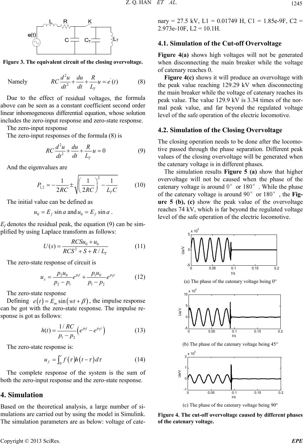 Z. Q. HAN ET AL. 1245 Figure 3. The equivalent circuit of the closing overvoltage. Namely 2' 2() du duR RC ue t (8) T dt L dt t of residual voltages, th aboves a constant coefficient second order lin Due to the effece formula can be seen a ear inhomogeneous differential equation, whose solution includes the zero-input response and zero-state response. The zero-input response The zero-input responses of the formula (8) is 2 du 20 T RC u dt L dt du R (9) And the eigenvalues are 2 1,2 2 PRC 111 2T RCL C (10) The initial value can be defined as aand a. Efon (9) can be sim- plified by using Laplace tr as follows: 0sin f uE0sin f uE denotes the residual peak, the equati ansform 00 2 () /T RCSu u Us RCSSR L (11) The zero-state response of circuit is 12 20 10 21 12 p tpt pupu e p (12) The zero-state response Defining x ue pp p sin m et Ewt e respo , the impul can bnse. The impulse re- sp se response e got with the zero-stat onse is got as follows: 12 1 1/ () 2 p tpt RC hte e p (13) p The zero-state response is: d t ufht 0 f (14) The complete response of the system both the zero-input response and the zero Based on the theoretical analysis, a large number of si- ied out by using the model in Simulink. The simulation parameters are as below: voltage of cate- voltages will not be generated voltage the voltage of catenary reaches its pe o- peak when hile the phase of is the sum of -state response. 4. Simulation mulations are carr nary = 27.5 kV, L1 = 0.01749 H, C1 = 1.85e-9F, C2 = 2.973e-10F, L2 = 10.1H. 4.1. Simulation of the Cut-off Overvoltage Figure 4(a) shows high when disconnecting the main breaker while the of catenary r e aches 0. Figure 4(c) shows it will produce an overvoltage with the peak value reaching 129.29 kV when disconnecting the main breaker while ak value. The value 129.9 kV is 3.34 times of the nor- mal peak value, and far beyond the regulated voltage level of the safe operation of the electric locomotive. 4.2. Simulation of the Closing Overvoltage The closing operation needs to be done after the locom tive passed through the phase separation. Different values of th e closing overvoltage will b e generated the catenary voltage is in different phases. The simulation results Figure 5 (a) show that higher overvoltage will not be caused when the phase of the catenary voltage is around 0°or 180°. W the catenary voltage is around 90°or 180°, the Fig- ure 5 (b), (c) show the peak value of the overvoltage reaches 74 kV, which is far beyond the regulated voltage level of the safe operation of the electric locomotive. 00.05 0.10.150.2 -5 0 5x 10 4 t/s Ua/V (a) The phase of the catenary voltage being 0° 00.05 0.10.15 0.2 -5 0 10 x 10 4 5 t/s Ua/ V (b) The phase of the catenary voltage being 45° 00.05 0.10.15 0.2 -1 0 2x 10 5 1 t/s Ua/ V (c) The phase of the catenary voltage being 90° Figure 4. The cut-off overvoltage caused by differen phases of the catena ry voltage. t Copyright © 2013 SciRes. EPE 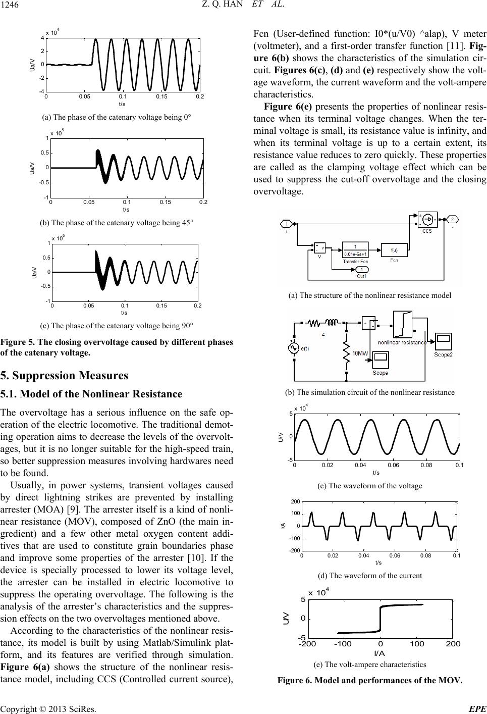 Z. Q. HAN ET AL. 1246 00.05 0.10.15 0.2 -4 -2 0 2 4x 10 4 /V t/s Ua (a) The phase of the catenary voltage being 0° 00.05 0.10.15 0.2 -1 -0. 5 0 0.5 1x 10 5 Ua/V t/s (b) The phase of the catenary voltage being 45° 00.05 0.10.15 0.2 -1 -0.5 0 0. 5 1x 10 5 t/s Ua/V (c) The phase of the catenary voltage being 90° Figure 5. The closing overvoltage caused by different phases of the catena ry voltage. linear Resistance fluence on the safe op- nal demot- e overvolt- ) [9]. The arrester itself is a kind of nonli- ne . Fi small, its resistance value is infinity, and w 5. Suppression Measures 5.1. Model of the Non The overvoltage has a serious in eration of the electric locomotive. The traditio ing operation aims to decrease th e levels of th ages, but it is no longer suitable for the high-speed train, so better suppression measures involving hardwares need to be found. Usually, in power systems, transient voltages caused by direct lightning strikes are prevented by installing arrester (MOA ar resistance (MOV), composed of ZnO (the main in- gredient) and a few other metal oxygen content addi- tives that are used to constitute grain boundaries phase and improve some properties of the arrester [10]. If the device is specially processed to lower its voltage level, the arrester can be installed in electric locomotive to suppress the operating overvoltage. The following is the analysis of the arrester’s characteristics and the suppres- sion effects on the two overvoltages mentioned above. According to the characteristics of the nonlinear resis- tance, its model is built by using Matlab/Simulink plat- form, and its features are verified through simulation gure 6(a) shows the structure of the nonlinear resis- tance model, including CCS (Controlled current source), Fcn (User-defined function: I0*(u/V0) ^alap), V meter (voltmeter), and a first-order transfer function [11]. Fig- ure 6(b) shows the characteristics of the simulation cir- cuit. Figures 6(c), (d) and (e) respectively show the volt- age waveform, the current waveform and the volt-ampere characteristics. Figure 6(e) presents the properties of nonlinear resis- tance when its terminal voltage changes. When the ter- minal voltage is hen its terminal voltage is up to a certain extent, its resistance value reduces to zero quickly. These properties are called as the clamping voltage effect which can be used to suppress the cut-off overvoltage and the closing overvoltage. (a) The structure of the nonlinear resistance model (b) The simulation circuit of the nonlinear resistance 00.02 0.04 0.06 0.08 0.1 -5 0 5x 10 4 U/ V t/s (c) The waveform of the voltage 00.02 0.04 0.060.080.1 -200 -100 0 100 200 t/s I/A (d) The waveform of the current -200 -100 0100 200 -5 0 5x 10 4 I/A U/V (e) The volt-ampere characteristics Figure 6. Model and performances of the MOV. Copyright © 2013 SciRes. EPE 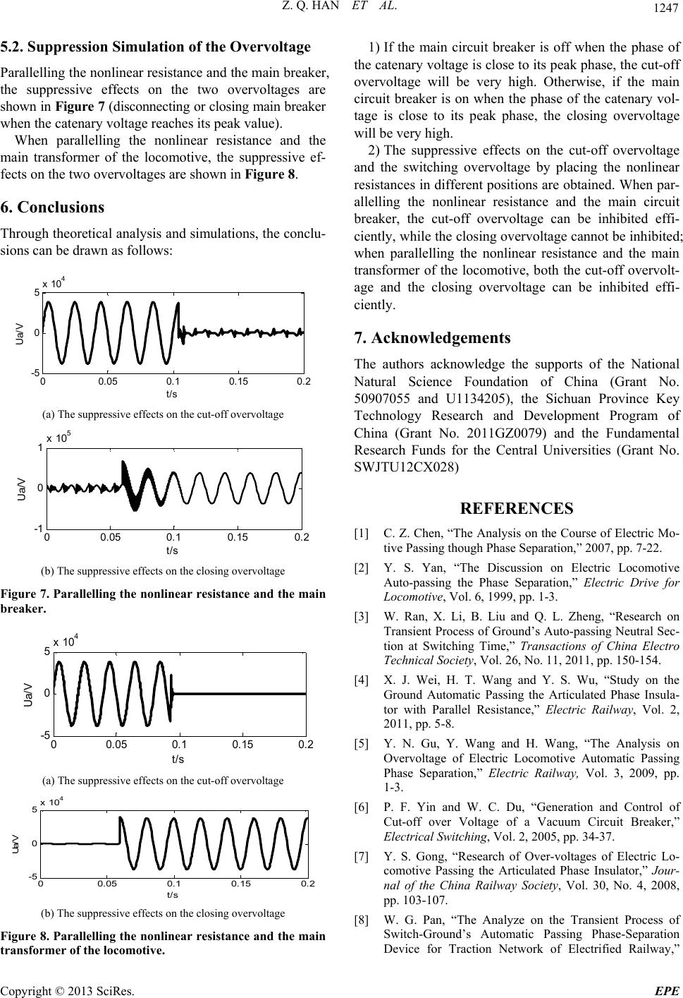 Z. Q. HAN ET AL. 1247 5.2. Suppression Simulation of the Overvoltage Parallelling the non linear resistance and the main break er, the suppressive effects on the two overvoltages are shown in Figure 7 (disconnecting or closing main breaker when the catenary voltage reaches its peak value). When paralnce ahe main transformer ouppressive ef- fects lelling the nonlinear resista f the locomotive, the snd t on the two overvoltages are shown in Figur e 8. 6. Conclusions Through theoretical analysis and simulations, the conclu- sions can be drawn as follows: 00.05 0.10.15 0.2 -5 0 5x 10 4 Ua/ V t/s (a) The suppressive effects on the cut-off overvoltage 00.05 0.10.15 0.2 -1 0 1x 10 5 t/s Ua/V (b) The suppre ssive effects on the closing overvoltage Figure 7. Parallelling the nonlinear resistance and the main breaker. 00.05 0.1 0.15 0.2 -5 0 5x 10 4 Ua/ V (a) The suppressive effects on the cut-off overvoltage t/s 00.05 0.1 0.15 0.2 -5 0 5x 10 4 Ua/V t/s (b) The suppre ssive effects on the closing overvoltage Figure e main transformer of the locomotive. 1) If the main circuit breaker is off when the phase of the catenary voltage is close to its peak phase, the cut-off overvoltage will be very high. Otherwise, if the main circuit breaker is on when the phase of the catenary vol- tage is close to its peak phase, the closing overvoltage will be very high. 2) Toltage X028) NCES s of Ground’s Auto-passing Neutral Sec- tion at Switching Time,” Transactions of China Electro Technical Soc1, pp. 150-154. [4] X. J. Wei, H.u, “Study on the ve Automatic Passing ,” a Railway Society, Vol. 30, No. 4, 2008, e for Traction Network of Electrified Railway,” 8. Parallelling the nonlinear resistance and th pp. he suppressive effects on the cut-off overv and the switching overvoltage by placing the nonlinear resistances in different positions are obtained. When par- allelling the nonlinear resistance and the main circuit breaker, the cut-off overvoltage can be inhibited effi- ciently, while the closing overvo ltage cannot be inhibited; when parallelling the nonlinear resistance and the main transformer of the locomotive, both the cut-off overvolt- age and the closing overvoltage can be inhibited effi- ciently. 7. Acknowledgements The authors acknowledge the supports of the National Natural Science Foundation of China (Grant No. 50907055 and U1134205), the Sichuan Province Key Technology Research and Development Program of China (Grant No. 2011GZ0079) and the Fundamental Research Funds for the Central Universities (Grant No. SWJTU12C REFERE [1] C. Z. Chen, “The Analysis on the Course of Electric Mo- tive Passing though Phase Separation,” 2007, pp. 7-22. [2] Y. S. Yan, “The Discussion on Electric Locomotive Auto-passing the Phase Separation,” Electric Drive for Locomotive, Vol. 6, 1999, pp. 1-3. [3] W. Ran, X. Li, B. Liu and Q. L. Zheng, “Research on Transient Proces iety, Vol. 26, No. 11, 201 T. Wang and Y. S. W Ground Automatic Passing the Articulated Phase Insula- tor with Parallel Resistance,” Electric Railway, Vol. 2, 2011, pp. 5-8. [5] Y. N. Gu, Y. Wang and H. Wang, “The Analysis on Overvoltage of Electric Locomoti Phase Separation,” Electric Railway, Vol. 3, 2009, pp. 1-3. [6] P. F. Yin and W. C. Du, “Generation and Control of Cut-off over Voltage of a Vacuum Circuit Breaker Electrical Switching, Vol. 2, 2005, pp. 34-37. [7] Y. S. Gong, “Research of Over-voltages of Electric Lo- comotive Passing the Articulated Phase Insulator,” Jour- nal of the Chin 103-107. [8] W. G. Pan, “The Analyze on the Transient Process of Switch-Ground’s Automatic Passing Phase-Separation Devic Copyright © 2013 SciRes. EPE 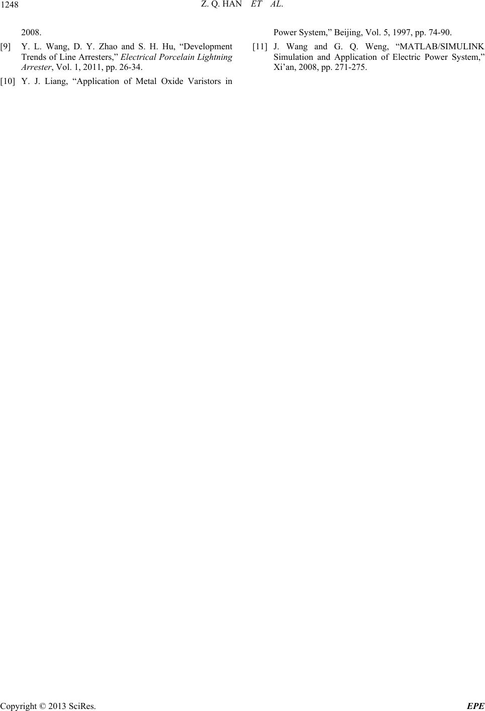 Z. Q. HAN ET AL. Copyright © 2013 SciRes. EPE 1248 Lightning System,” Beijing, Vol. 5, 1997, pp. 74-90. 2008. [9] Y. L. Wang, D. Y. Zhao and S. H. Hu, “Development Trends of Line Arresters,” Electrical Porcelain [11 Arrester, Vol. 1, 2011, pp. 26-34. [10] Y. J. Liang, “Application of Metal Oxide Varistors in Power ] J. Wang and G. Q. Weng, “MATLAB/SIMULINK Simulation and Application of Electric Power System,” Xi’an, 2008, pp. 271-275. |