B. R. ZHOU ET AL. 1231
solved with much smaller integration steps compared to
AC system. Since the response model of HVDC in
PSS/E is simple and flexible and can simulate various
dynamics of HVDC conveniently and simply, it is easy
to implement sensitivity analysis about the effect of DC
system dynamic characteristics on stability and security
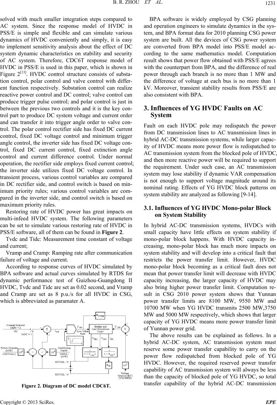
of AC system. Therefore, CDC6T response model of
HVDC in PSS/E is used in this paper, which is shown in
Figure 2[13]. HVDC control structure consists of substa-
tion control, polar control and valve control with differ-
ent function respectively. Substation control can realize
reactive power control and DC control; valve control can
produce trigger pulse control; and polar control is just in
between the previous two controls and it is the key con-
trol part to produce DC system voltage and current order
and can transfer it into trigger angle order to valve con-
trol. The polar control rectifier side has fixed DC current
control, fixed DC voltage control and minimum trigger
angle control, the inverter side has fixed DC voltage con-
trol, fixed DC current control, fixed extinction angle
control and current difference control. Under normal
operation, the rectifier side employs fixed current control;
the inverter side utilizes fixed DC voltage control. In
transient process, various control variables are compared
in DC rectifier side, and control switch is based on min-
imum priority rules; various control variables are com-
pared in the inverter side, and control switch is based on
maximum priority rules.
Restoring rate of HVDC power has great impacts on
multi-infeed HVDC system. The following parameters
can be set to simulate various restoring rate of HVDC in
PSS/E software, all of them can be found in Figure 2.
Tvdc and Tidc: Measurement time constant of voltage
and current;
Vramp and Cramp: Ramping rate after communication
failure of v o l t age and cu r r ent.
According to response curves of HVDC simulated by
BPA software and actual curves simulated by RTDS for
dynamic performance test of Guizhou-Guangdong II
HVDC, Tvdc and Tidc are set as 0 .02 second, and Vramp
and Cramp are set as 8 p.u./s for all HVDC in CSG,
which is abbreviated as paramater A.
Figure 2. Diagram of DC model CDC6T.
BPA software is widely employed by CSG planning
and operation engineers to simulate dynamics in the sys-
tem, and BPA format data for 2010 plan ning CSG power
system are built. All the devices of CSG power system
are converted from BPA model into PSS/E model ac-
cording to the same mathematics model. Computation
result shows that power flow obtained with PSS/E agrees
with the counterpart from BPA, and the difference of real
power through each branch is no more than 1 MW and
the difference of voltage at each bus is no more than 1
kV. Moreover, transient stability results from PSS/E are
also consistent with BPA.
3. Influences of YG HVDC Faults on AC
System
Fault on each HVDC pole may redispatch the power
from DC transmission lines to AC transmission lines in
hybrid AC-DC transmission systems, while larger capac-
ity of HVDC means more power flow is redispatched to
AC transmission system from the blocked pole of HVDC,
and then more reactive power will be required to support
the requirement. Under such case, an AC transmission
system may lose stability if dynamic VAR compensatio n
is not enough to support voltage magnitude around its
nominal rating. Effects of YG HVDC block patterns on
system stability are analyzed as following [9-14].
3.1. Influences of YG HVDC Mono-polar Block
on System Stability
In hybrid AC-DC transmission systems, HVDCs with
small capacity have little effects on system stability if
mono-polar block happens. With HVDC capacity in-
creasing, mono-polar block has much more impacts on
system stability and will develop into a critical fault that
restricts the power transfer limit. However, HVDC
mono-polar block becoming as a critical fault does not
mean that power transfer limit will decrease with HVDC
capacity increasing, the larger capacity of HVDC may
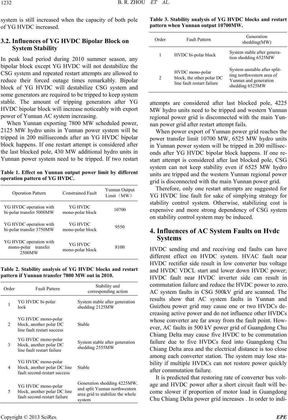
also bring higher power transfer limit. Computation re-
sult in CSG 2010 power system shows that Yunnan
power transfer limits are 8100 MW, 9550 MW and
10700 MW when YG HVDC transmits 2500 MW,3750
MW and 5000 MW respectively, which sh ows that larger
capacity of YG HVDC means more power transfer limit
of Yunnan power grid.
The above results can be explained as follows. In a
hybrid AC-DC system, AC transmission system must
reserve some power transfer capability to carry on the
power flow redispatched from blocked pole of YG
HVDC. However, the required reserved power transfer
capability of AC transmission system will always be less
than the capacity of blocked pole of YG HVDC, so total
transfer capability of the hybrid AC-DC transmission
Copyright © 2013 SciRes. EPE