X. PENG, Y. JIANG 1199
2.1. The Research on the Fault Location
Principle of the Earthing Electrode Line
When the DC system runs in BP mode, the imbalance
current flowed through the earthing electrode line is very
few, which is usually no more than 1% of the system
rated current; also the voltage at the outlet end of the
earthing electrode line (end of the converter station) is
only a dozens of volts, which makes it difficult for the
fault monitoring of the earthing electrode line running
under the BP mode.
Currently, th e fault location principles in the applica-
tion of the HVDC and UHVDC earthing electrode line
have the impedance method (ABB) [3] and the Time
Domain Reflectometry (SIMENS) [4]. As the impedance
method is unable to determine the fault type and fault
location, have the disadvantages of unwanted action or
refusing action and the settin g valu es are great in fluen ced
by the earthing transition resistance, so the existing
UHVDC transmission system is widely using the Time
Domain Reflectometry.
2.2. Time Domain Reflectometry
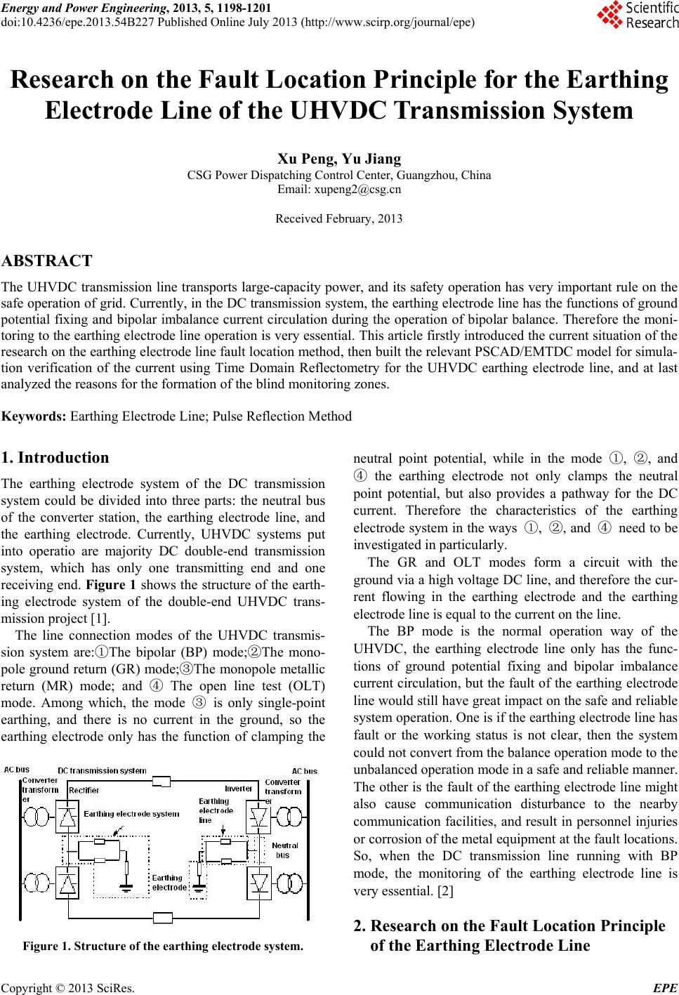
Based on the theory of long distance transmission line,
the Time Domain Reflectometry [5] is a type of line
monitoring method to determine the fault location, ac-
cording to the amplitude, polarity, arrival time, or other
electrical signals of the reflected pulse on the conductor
which detected by inputting a high frequency pulse sig-
nal to one end of the conductor [6-8]. Figure 2 shows
different characteristics between normal and abnormal.
The basic principle of the Time Domain Reflectometry
[9-10] which applied to the earthing electrode line is as
follows: apply the first voltage pulse at the side of the
end of the converter station of the earthing electrode line
and on the earthing electrode line at the same time, the
pulse goes through the earthing electrode line and is re-
flected when reaching the earthing electrode. Take the
record of the voltage wave on the line at the applying
position of the pulse, and when recording the reflected
wave at the end of the earthing electrode line, apply the
Figure 2. The Time Domain Reflectometry principle.
second pulse. Repeat the above processes until the fault
of the line and receiving the “extra” reflected wave. If the
earthing electrode line has fault, the fault poin t will form
a wave impedance singularity, which is a reflection point
for the pulse in addition to the earthing electrode, and by
the reflection of the pulse at this location, a measurable
reflected pulse in addition is generated. After receiving
this reflected pulse, stop to apply the monitoring pulse.
The reflected pulse at the fault point arrives at the pulse
applying point earlier than the reflected pulse at the end
of the earthing electrode line, and according to the return
time of the reflected pulse at the fault point and wave
velocity, the distance between the fault point and the
monitoring point is determined as
/
1
lv
2
t
(1)
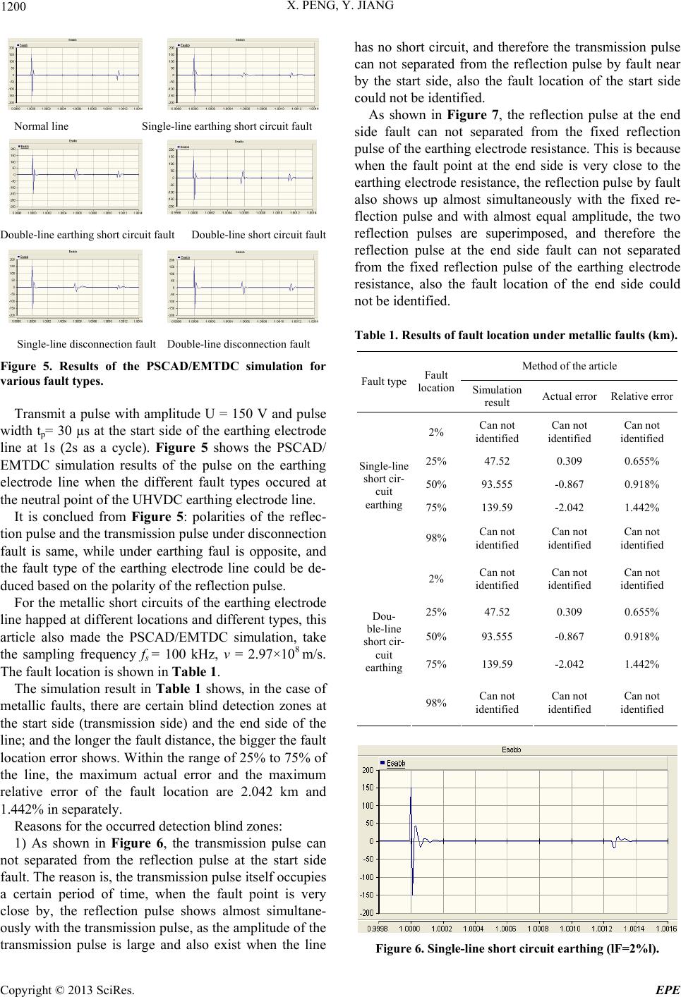
3. Simulation Verification
In order to verify the correctness and the validity of the
Time Domain Reflectometry proposed in this article, the
simulation model of the ±800kV UHVDC transmission
system is established by using the PSCAD/EMTDC
electromagnetic transient simulation software, which is
shown in Figure 3.
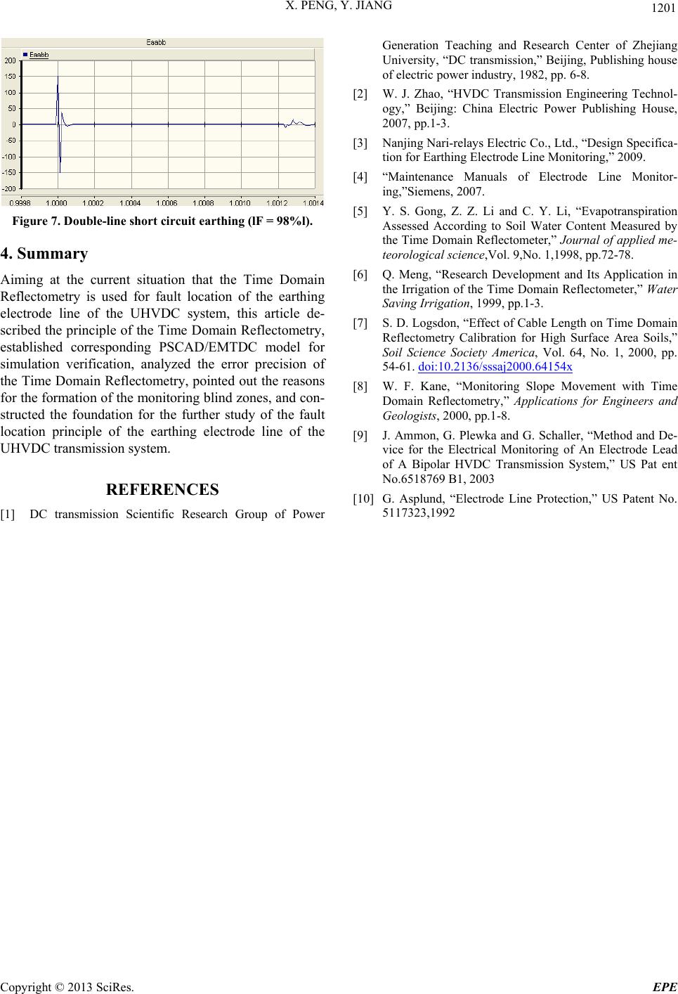
Figure 4 shows the line parameters of the earthing
electrode line of UHVDC transmission.
Figure 3. Simulation model of the ±500 kV HVDC trans-
mission system.
Figure 4. Model of the e arthing electrode line.
Copyright © 2013 SciRes. EPE