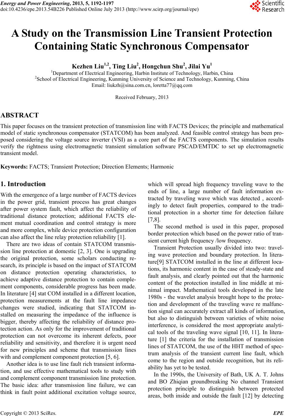
 Energy and Power Engineering, 2013, 5, 1192-1197 doi:10.4236/epe.2013.54B226 Published Online July 2013 (http://www.scirp.org/journal/epe) A Study on the Transmission Line Transient Protection Containing Static Synchronous Compensator Kezhen Liu1,2, Ting Liu2, Hongchun Shu2, Jilai Yu1 1Department of Electrical Engineering, Harbin Institute of Technology, Harbin, China 2School of Electrical Engineering, Kunming University of Science and Technology, Kunming, China Email: liukzh@sina.com.cn, loretta77@qq.com Received February, 2013 ABSTRACT This paper focuses on the transient protection of transmission line with FACTS Devices; the principle and mathematical model of static synchronous compensator (STATCOM) has been analyzed. And feasible control strategy has been pro- posed considering the voltage source inverter (VSI) as a core part of the FACTS components. The simulation results verify the rightness using electromagnetic transient simulation software PSCAD/EMTDC to set up electromagnetic transient model. Keywords: FACTS; Transient Protection; Direction Elements; Harmonic 1. Introduction With the emergence of a large number of FACTS devices in the power grid, transient process has great changes after power system fault, which affect the reliability of traditional distance protection; additional FACTS ele- ment mutual coordination and control strategy is more and more complex, while device protection configuration can also affect the line relay protection reliability [1]. There are two ideas of contain STATCOM transmis- sion line protection at domestic [2, 3]. One is upgrading the original protection, some scholars conducting re- search, its principle is based on the impact of STATCOM on distance protection operating characteristics, to achieve adaptive distance protection to contain comple- ment components, considerable progress has been made. In literature [4] stat COM installed in a different location, protection measurements at the fault line impedance changes were studied, indicating that STATCOM in- stalled on measuring the impedance of the influence is bigger, thereby affecting the reliability of distance pro- tection action. As only for the improvement of traditional protection can not overcome its inherent defects, poor reliability and sensitivity, and therefore it is urgent need for new principles and scheme that transmission lines with and complement component protection [5, 6]. Another idea is to use line fault rich transient informa- tion, and use effective mathematical tools to study with and complement component transmission line protection. The basic idea: after transmission line failure, we can think in fault point additional excitation voltage source, which will spread high frequency traveling wave to the ends of line, a large number of fault information ex- tracted by traveling wave which was detected , accord- ingly to detect fault properties, compared to the tradi- tional protection in a shorter time for detection failure [7,8]. The second method is used in this paper, proposed border protection which based on the power ratio of tran- sient current high frequency /low frequency. Transient Protection usually divided into two: travel- ing wave protection and boundary protection. In litera- ture[9] STATCOM installed in the line at different loca- tions, its harmonic content in the case of steady-state and fault analysis, and clearly pointed out that the harmonic content of the protection installed in line middle at mi- nimal impact. Mathematical tools developed in the late 1980s - the wavelet analysis brought hope to the protec- tion and development of the traveling wave re malfunc- tion signal can accurately extract all kinds of information, but also to distinguish between varieties of white noise interference, is considered the most appropriate analyti- cal tools of the traveling wave signal [10, 11]. In litera- ture [1] the criteria for the installation of transmission lines of STATCOM, the use of the HHT method of spec- trum analysis of the transient current line fault, which come to the region and outside recognition, but its reli- ability has yet to be tested. In the 1990s, the University of Bath, UK A. T. Johns and BO Zhiqian groundbreaking No channel Transient protection principle to distinguish between protected areas, both inside and outside the fault [12] by detecting Copyright © 2013 SciRes. EPE 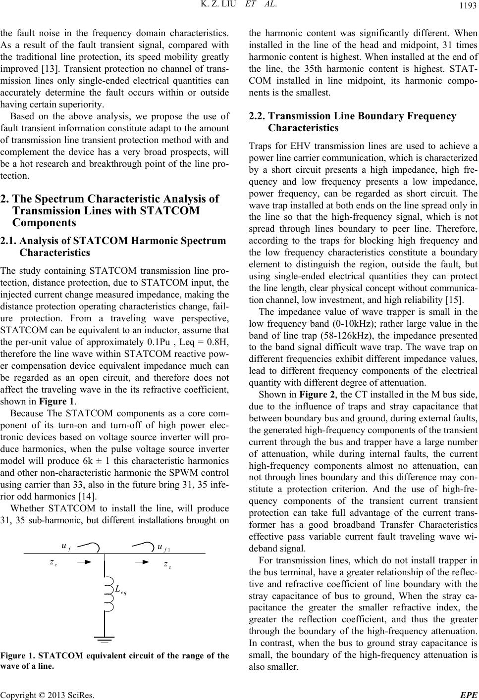 K. Z. LIU ET AL. 1193 the fault noise in the frequency domain characteristics. As a result of the fault transient signal, compared with the traditional line protection, its speed mobility greatly improved [13]. Transient protection no channel of trans- mission lines only single-ended electrical quantities can accurately determine the fault occurs within or outside having certain superiority. Based on the above analysis, we propose the use of fault transient information constitute adapt to the amount of transmission line transient protection method with and complement the device has a very broad prospects, will be a hot research and breakthrough point of the line pro- tection. 2. The Spectrum Characteristic Analysis of Transmission Lines with STATCOM Components 2.1. Analysis of STATCOM Harmonic Spectrum Characteristics The study containing STATCOM transmission line pro- tection, distance protection, due to STATCOM input, the injected current change measured impedance, making the distance protection operating characteristics change, fail- ure protection. From a traveling wave perspective, STATCOM can be equivalent to an inductor, assume that the per-unit value of approximately 0.1Pu , Leq = 0.8H, therefore the line wave within STATCOM reactive pow- er compensation device equivalent impedance much can be regarded as an open circuit, and therefore does not affect the traveling wave in the its refractive coefficient, shown in Figure 1. Because The STATCOM components as a core com- ponent of its turn-on and turn-off of high power elec- tronic devices based on voltage source inverter will pro- duce harmonics, when the pulse voltage source inverter model will produce 6k ± 1 this characteristic harmonics and other non-characteristic harmonic the SPWM control using carrier than 33, also in the future bring 31, 35 infe- rior odd harmonics [14]. Whether STATCOM to install the line, will produce 31, 35 sub-harmonic, but different installations brought on f u c z eq L 1f u c z Figure 1. STATCOM equivalent circuit of the range of the wave of a line. the harmonic content was significantly different. When installed in the line of the head and midpoint, 31 times harmonic content is highest. When installed at the end of the line, the 35th harmonic content is highest. STAT- COM installed in line midpoint, its harmonic compo- nents is the smallest. 2.2. Transmission Line Boundary Frequency Characteristics Traps for EHV transmission lines are used to achieve a power line carrier communication, which is characterized by a short circuit presents a high impedance, high fre- quency and low frequency presents a low impedance, power frequency, can be regarded as short circuit. The wave trap installed at both ends on the line spread only in the line so that the high-frequency signal, which is not spread through lines boundary to peer line. Therefore, according to the traps for blocking high frequency and the low frequency characteristics constitute a boundary element to distinguish the region, outside the fault, but using single-ended electrical quantities they can protect the line length, clear physical concept without communica- tion channel, low investment, and high reliability [15]. The impedance value of wave trapper is small in the low frequency band (0-10kHz); rather large value in the band of line trap (58-126kHz), the impedance presented to the band signal difficult wave trap. The wave trap on different frequencies exhibit different impedance values, lead to different frequency components of the electrical quantity with different degree of attenuation. Shown in Figure 2, the CT installed in the M bus side, due to the influence of traps and stray capacitance that between boundary bus and ground, during external faults, the generated high-frequency components of the transient current through the bus and trapper have a large number of attenuation, while during internal faults, the current high-frequency components almost no attenuation, can not through lines boundary and this difference may con- stitute a protection criterion. And the use of high-fre- quency components of the transient current transient protection can take full advantage of the current trans- former has a good broadband Transfer Characteristics effective pass variable current fault traveling wave wi- deband signal. For transmission lines, which do not install trapper in the bus terminal, have a greater relationship of the reflec- tive and refractive coefficient of line boundary with the stray capacitance of bus to ground, When the stray ca- pacitance the greater the smaller refractive index, the greater the reflection coefficient, and thus the greater through the boundary of the high-frequency attenuation. In contrast, when the bus to ground stray capacitance is small, the boundary of the high-frequency attenuation is also smaller. Copyright © 2013 SciRes. EPE 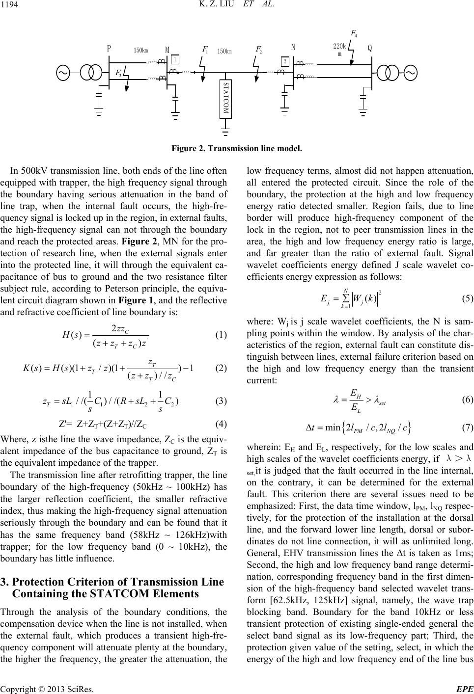 K. Z. LIU ET AL. Copyright © 2013 SciRes. EPE 1194 2 1 PN M 2 F 3 F Q 150km 220k m 4 F 150km 1 F STATCOM Figure 2. Transmission line model. In 500kV transmission line, both ends of the line often equipped with trapper, the high frequency signal through the boundary having serious attenuation in the band of line trap, when the internal fault occurs, the high-fre- quency signal is locked up in the region, in external faults, the high-frequency signal can not through the boundary and reach the protected areas. Figure 2, MN for the pro- tection of research line, when the external signals enter into the protected line, it will through the equivalent ca- pacitance of bus to ground and the two resistance filter subject rule, according to Peterson principle, the equiva- lent circuit diagram shown in Figure 1, and the reflective and refractive coefficient of line boundary is: ' 2 () () C TC zz Hs zz zz (1) ()()(1/ )(1)1 ()// T TTC z KsHsz zzz z (2) 11 2 1 //( )//() T zsLCRsLC ss 2 1 (3) Z'= Z+ZT+(Z+ZT)//ZC (4) Where, z isthe line the wave impedance, ZC is the equiv- alent impedance of the bus capacitance to ground, ZT is the equivalent impedance of the trapper. The transmission line after retrofitting trapper, the line boundary of the high-frequency (50kHz ~ 100kHz) has the larger reflection coefficient, the smaller refractive index, thus making the high-frequency signal attenuation seriously through the boundary and can be found that it has the same frequency band (58kHz ~ 126kHz)with trapper; for the low frequency band (0 ~ 10kHz), the boundary has little influence. 3. Protection Criterion of Transmission Line Containing the STATCOM Elements Through the analysis of the boundary conditions, the compensation device when the line is not installed, when the external fault, which produces a transient high-fre- quency component will attenuate plenty at the boundary, the higher the frequency, the greater the attenuation, the low frequency terms, almost did not happen attenuation, all entered the protected circuit. Since the role of the boundary, the protection at the high and low frequency energy ratio detected smaller. Region fails, due to line border will produce high-frequency component of the lock in the region, not to peer transmission lines in the area, the high and low frequency energy ratio is large, and far greater than the ratio of external fault. Signal wavelet coefficients energy defined J scale wavelet co- efficients energy expression as follows: 2 1 () N jj k EWk (5) where: Wj is j scale wavelet coefficients, the N is sam- pling points within the window. By analysis of the char- acteristics of the region, external fault can constitute dis- tinguish between lines, external failure criterion based on the high and low frequency energy than the transient current: H et L E E (6) min2/, 2/ PM NQ tlcl c (7) wherein: EH and EL, respectively, for the low scales and high scales of the wavelet coefficients energy, if λ>λ set,it is judged that the fault occurred in the line internal, on the contrary, it can be determined for the external fault. This criterion there are several issues need to be emphasized: First, the data time window, lPM, lNQ respec- tively, for the protection of the installation at the dorsal line, and the forward lower line length, dorsal or subor- dinates do not line connection, it will as unlimited long. General, EHV transmission lines the Δt is taken as 1ms; Second, the high and low frequency band range determi- nation, corresponding frequency band in the first dimen- sion of the high-frequency band selected wavelet trans- form [62.5kHz, 125kHz] signal, namely, the wave trap blocking band. Boundary for the band 10kHz or less transient protection of existing single-ended general the select band signal as its low-frequency part; Third, the protection given value of the setting, select, in which the energy of the high and low frequency end of the line bus 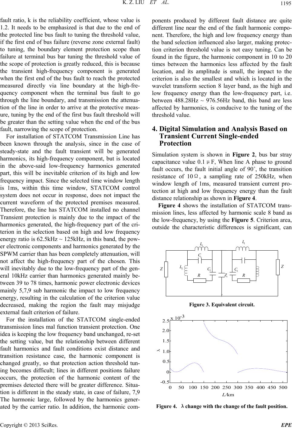 K. Z. LIU ET AL. 1195 fault ratio, k is the reliability coefficient, whose value is 1.2. It needs to be emphasized is that due to the end of the protected line bus fault to tuning the threshold value, if the first end of bus failure (reverse zone external fault) to tuning, the boundary element protection scope than failure at terminal bus bar tuning the threshold value of the scope of protection is greatly reduced, this is because the transient high-frequency component is generated when the first end of the bus fault to reach the protected measured directly via line boundary at the high-fre- quency component when the terminal bus fault to go through the line boundary, and transmission the attenua- tion of the line in order to arrive at the protective meas- ure, tuning by the end of the first bus fault threshold will be greater than the setting value when the end of the bus fault, narrowing the scope of protection. For installation of STATCOM Transmission Line has been known through the analysis, since in the case of steady-state and the fault transient will be generated harmonics, its high-frequency component, but is located in the above-said low-frequency harmonics generated part, this will be inevitable criterion of its high and low frequency impact. Since the selected time window length is 1ms, within this time window, STATCOM control system does not occur in response, does not impact the current waveform of the protected premises measured. Therefore, the line has STATCOM installed no channel Transient protection is mainly due to the impact of the harmonics generated, the high-frequency part of the cri- terion in the selection based on high and low frequency energy ratio is 62.5kHz ~ 125kHz, in this band, the pow- er electronic components and harmonics generated by the SPWM carrier than has been completely attenuation, will not affect the high-frequency part of the chosen. This will inevitably due to the low-frequency part of the gen- eral 10kHz carrier than harmonics generated mainly be- tween 39 to 78 times, harmonic power electronic devices mainly 5,7,9 sub harmonic the impact to low frequency energy, resulting in the calculation of the criterion value decreased, making the region the fault may misjudge external fault criterion of failure. For the installation of the STATCOM single-ended transmission lines mal function transient protection. One idea is keeping the low frequency band unchanged, re-set the setting value, but the relationship between different fault harmonics and fault conditions exist distance and transition resistance case, the harmonic component is changed greatly, so that protection action threshold tun- ing becomes difficult; lines in different positions failure occurs, the protection of the harmonic content of the premises detected there will be greater difference. Situa- tion is different in the steady state, in case of failure, 7,9 The harmonic large, followed by the harmonics gener- ated by the carrier ratio. In addition, the harmonic com- ponents produced by different fault distance are quite different line near the end of the fault harmonic compo- nent. Therefore, the high and low frequency energy than the band selection influenced also larger, making protec- tion criterion threshold value is not easy tuning. Can be found in the figure, the harmonic component in 10 to 20 times between the harmonics less affected by the fault location, and its amplitude is small, the impact to the criterion is also the smallest and which is located in the wavelet transform section 8 layer band, as the high and low frequency energy than the low-frequency part, i.e. between 488.28Hz ~ 976.56Hz band, this band are less affected by harmonics, is conducive to the tuning of the threshold value. 4. Digital Simulation and Analysis Based on Transient Cu rrent Single- ended Protection Simulation system is shown in Figure 2, bus bar stray capacitance value 0.1μF, When line A phase to ground fault occurs, the fault initial angle of 90˚, the transition resistance of 10Ω, a sampling rate of 250kHz, when window length of 1ms, measured transient current pro- tection at high and low frequency energy than the fault distance relationship as shown in Fig ure 4. Figure 4 shows the installation of STATCOM trans- mission lines, less affected by harmonic scale 8 band as the low-frequency, by using the Figure 5. Criterion area, outside the characteristic differences is significant, can 1 L 1 C 2 L 2 C R Z c Z2 C 1 L R Figure 3. Equivalent circuit. 050 100 150 200250 300 350 400450500 -0.5 0 0.5 1.0 1.5 2.0 2.5 /km λ x 10-3 Figure 4. λchange with the change of the fault position. Copyright © 2013 SciRes. EPE 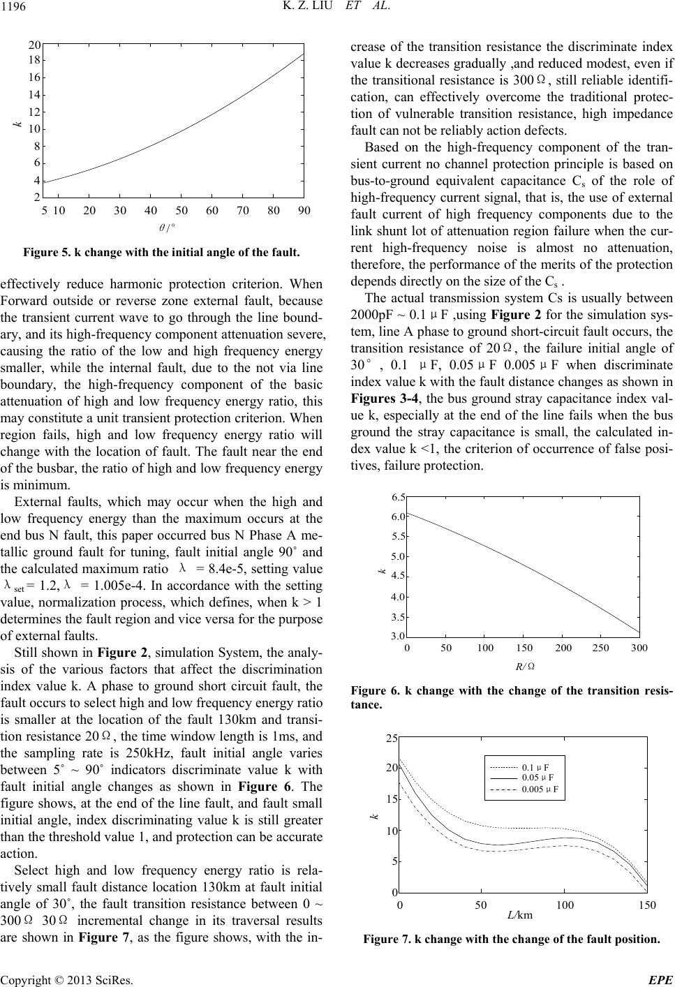 K. Z. LIU ET AL. 1196 1020 3040 506070 8090 2 4 6 8 10 12 14 16 18 20 5 θ /° Figure 5. k change with the initial angle of the fault. effectively reduce harmonic protection criterion. When Forward outside or reverse zone external fault, because the transient current wave to go through the line bound- ary, and its high-frequency component attenuation severe, causing the ratio of the low and high frequency energy smaller, while the internal fault, due to the not via line boundary, the high-frequency component of the basic attenuation of high and low frequency energy ratio, this may constitute a unit transient protection criterion. When region fails, high and low frequency energy ratio will change with the location of fault. The fault near the end of the busbar, the ratio of high and low frequency energy is minimum. External faults, which may occur when the high and low frequency energy than the maximum occurs at the end bus N fault, this paper occurred bus N Phase A me- tallic ground fault for tuning, fault initial angle 90˚ and the calculated maximum ratio λ = 8.4e-5, setting value λset = 1.2,λ = 1.005e-4. In accordance with the setting value, normalization process, which defines, when k > 1 determines the fault region and vice versa for the purpose of external faults. Still shown in Figure 2, simulation System, the analy- sis of the various factors that affect the discrimination index value k. A phase to ground short circuit fault, the fault occurs to select high and low frequency energy ratio is smaller at the location of the fault 130km and transi- tion resistance 20Ω, the time window length is 1ms, and the sampling rate is 250kHz, fault initial angle varies between 5˚ ~ 90˚ indicators discriminate value k with fault initial angle changes as shown in Figure 6. The figure shows, at the end of the line fault, and fault small initial angle, index discriminating value k is still greater than the threshold value 1, and protection can be accurate action. Select high and low frequency energy ratio is rela- tively small fault distance location 130km at fault initial angle of 30˚, the fault transition resistance between 0 ~ 300Ω 30Ω incremental change in its traversal results are shown in Figure 7, as the figure shows, with the in- crease of the transition resistance the discriminate index value k decreases gradually ,and reduced modest, even if the transitional resistance is 300Ω, still reliable identifi- cation, can effectively overcome the traditional protec- tion of vulnerable transition resistance, high impedance fault can not be reliably action defects. Based on the high-frequency component of the tran- sient current no channel protection principle is based on bus-to-ground equivalent capacitance Cs of the role of high-frequency current signal, that is, the use of external fault current of high frequency components due to the link shunt lot of attenuation region failure when the cur- rent high-frequency noise is almost no attenuation, therefore, the performance of the merits of the protection depends directly on the size of the Cs . The actual transmission system Cs is usually between 2000pF ~ 0.1μF ,using Figure 2 for the simulation sys- tem, line A phase to ground short-circuit fault occurs, the transition resistance of 20Ω, the failure initial angle of 30°, 0.1 μF, 0.05μF 0.005μF when discriminate index value k with the fault distance changes as shown in Figures 3-4, the bus ground stray capacitance index val- ue k, especially at the end of the line fails when the bus ground the stray capacitance is small, the calculated in- dex value k <1, the criterion of occurrence of false posi- tives, failure protection. 050100 150 200 250300 3.0 3.5 4.0 4.5 5.0 5.5 6.0 6.5 /Ω Figure 6. k change with the change of the transition resis- tance. 050100 150 0 5 10 15 20 25 0.1μF 0.05μF 0.005μF /km Figure 7. k change with the change of the fault position. Copyright © 2013 SciRes. EPE 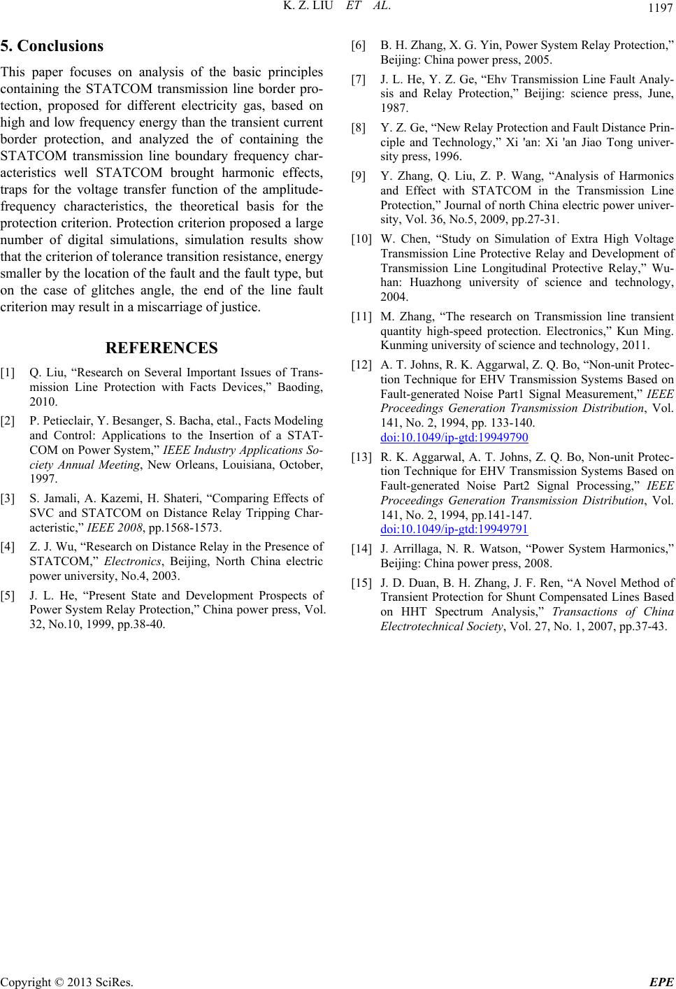 K. Z. LIU ET AL. Copyright © 2013 SciRes. EPE 1197 5. Conclusions This paper focuses on analysis of the basic principles containing the STATCOM transmission line border pro- tection, proposed for different electricity gas, based on high and low frequency energy than the transient current border protection, and analyzed the of containing the STATCOM transmission line boundary frequency char- acteristics well STATCOM brought harmonic effects, traps for the voltage transfer function of the amplitude- frequency characteristics, the theoretical basis for the protection criterion. Protection criterion proposed a large number of digital simulations, simulation results show that the criterion of tolerance transition resistance, energy smaller by the location of the fault and the fault type, but on the case of glitches angle, the end of the line fault criterion may result in a miscarriage of justice. REFERENCES [1] Q. Liu, “Research on Several Important Issues of Trans- mission Line Protection with Facts Devices,” Baoding, 2010. [2] P. Petieclair, Y. Besanger, S. Bacha, etal., Facts Modeling and Control: Applications to the Insertion of a STAT- COM on Power System,” IEEE Industry Applications So- ciety Annual Meeting, New Orleans, Louisiana, October, 1997. [3] S. Jamali, A. Kazemi, H. Shateri, “Comparing Effects of SVC and STATCOM on Distance Relay Tripping Char- acteristic,” IEEE 2008, pp.1568-1573. [4] Z. J. Wu, “Research on Distance Relay in the Presence of STATCOM,” Electronics, Beijing, North China electric power university, No.4, 2003. [5] J. L. He, “Present State and Development Prospects of Power System Relay Protection,” China power press, Vol. 32, No.10, 1999, pp.38-40. [6] B. H. Zhang, X. G. Yin, Power System Relay Protection,” Beijing: China power press, 2005. [7] J. L. He, Y. Z. Ge, “Ehv Transmission Line Fault Analy- sis and Relay Protection,” Beijing: science press, June, 1987. [8] Y. Z. Ge, “New Relay Protection and Fault Distance Prin- ciple and Technology,” Xi 'an: Xi 'an Jiao Tong univer- sity press, 1996. [9] Y. Zhang, Q. Liu, Z. P. Wang, “Analysis of Harmonics and Effect with STATCOM in the Transmission Line Protection,” Journal of north China electric power univer- sity, Vol. 36, No.5, 2009, pp.27-31. [10] W. Chen, “Study on Simulation of Extra High Voltage Transmission Line Protective Relay and Development of Transmission Line Longitudinal Protective Relay,” Wu- han: Huazhong university of science and technology, 2004. [11] M. Zhang, “The research on Transmission line transient quantity high-speed protection. Electronics,” Kun Ming. Kunming university of science and technology, 2011. [12] A. T. Johns, R. K. Aggarwal, Z. Q. Bo, “Non-unit Protec- tion Technique for EHV Transmission Systems Based on Fault-generated Noise Part1 Signal Measurement,” IEEE Proceedings Generation Transmission Distribution, Vol. 141, No. 2, 1994, pp. 133-140. doi:10.1049/ip-gtd:19949790 [13] R. K. Aggarwal, A. T. Johns, Z. Q. Bo, Non-unit Protec- tion Technique for EHV Transmission Systems Based on Fault-generated Noise Part2 Signal Processing,” IEEE Proceedings Generation Transmission Distribution, Vol. 141, No. 2, 1994, pp.141-147. doi:10.1049/ip-gtd:19949791 [14] J. Arrillaga, N. R. Watson, “Power System Harmonics,” Beijing: China power press, 2008. [15] J. D. Duan, B. H. Zhang, J. F. Ren, “A Novel Method of Transient Protection for Shunt Compensated Lines Based on HHT Spectrum Analysis,” Transactions of China Electrotechnical Society, Vol. 27, No. 1, 2007, pp.37-43.
|