Energy and Power Engineering, 2013, 5, 1187-1191
doi:10.4236/epe.2013.54B225 Published Online July 2013 (http://www.scirp.org/journal/epe)
Coordinated Control of Multi-FACTS to Enhance the
Dynamic Stability of the Power System
Rui Min1, Fei Xu1, Fei Yuan2, Zonghe Gao2
1Department of Electrica l Engineer ing, Tsinghua University, Bei Jing, China
2NARI Technology Development Co., Ltd, Nanjing, China
Received February, 2013
ABSTRACT
This article introduces a FACTS coordinated control strategy with impedance/admittance measurement feedb ack. Then
the effectiveness of this method is proved in mathematics with damp torque method. The control strategy effect is veri-
fied in a single machine infinite bus system and a four machine power system with PSASP6.26 (Power System Analysis
Software Package). This coordinated control strategy has practical significance to improve system dynamic stability a n d
theoretical significance to improve system transient stability.
Keywords: Coordinated Control; Dynamic Stability; Measurement Feedback; SVC; TCSC; Transient Stability
1. Introduction
The power grid of China has entered the ultra-high volt-
age (UHV) period with large complicated power system.
A large power grid needs more people to supervise and
has more equipment to control because of its complicated
structure. In addition , although the development of smart
grid brings many opportunities to us, operators have
more and more challenges to run the grid and avoid ac-
cidents. In this context, our smart grid needs more flexi-
ble and reliable control methods to reduce network losses,
improve the f low distribution, improve the system stabil-
ity, raise the level of power system damping and so on.
FACTS device can be regulated reliable with fast re-
sponse. Individual FACTS device can improve the local
power grid status with appropriate control strategies in a
short period of time. If multiple FACTS devices in dif-
ferent areas can be coordinated with appropriate control
strategies, the entire grid (or parts of) will have a better
control results. With the widely application of FACTS
devices, the coordination control problem of FACTS
devices has an increasingly importan t position [1].
2. FACTS Coordinated Control Strategy
with Measurement Feedback
2.1. Coordinated Control of TCSC with SVC
Admittance Inputs Signal
The TCSC input control signal is determin ed by the con-
trol strategy, such as the acceleration power of the gen-
erator and active and reactive power flow of transmission
lines. The most commonly scene to use TCSC is to con-
trol the electromagnetic power of the series branch,
which use electromagnetic power deviation as inputs.
The PI controller parameters and control effect are con-
strained by TCSC capacity. When TCSC use conven-
tional PI control, the system dynamic stability can be
improved more [2].
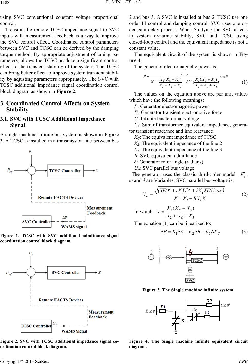
Transmit the remote SVC admittance signal to TCSC
inputs with measurement feedback is a way to improve
the TCSC control effect. Coordinated control parameters
between TCSC and SVC can be derived by the damping
torque method. By appropriate adjustment of tuning pa-
rameters, allows the SVC produce a significant control
effect to the dynamic stability of the system. The SVC
can bring better effect to improve system dynamic stabil-
ity by adjusting parameters appropriately. The TCSC
with SVC additional ad mittance signal co ordination con-
trol block diagram as shown in Figure 1:
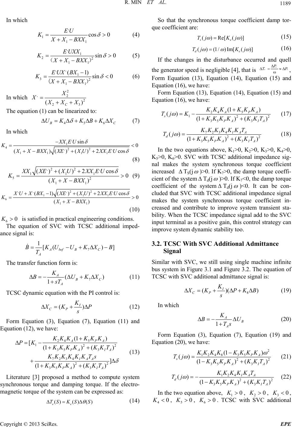
2.2. Coordinated Control of SVC with TCSC
Impedance Inputs Signal
The most commonly scene to use SVC is to maintain the
stability of the syste m voltage. In addition, SVC can also
be used to improve the dynamic and static stability per-
formance of the power system and to improve grid dy-
namic stability and damping.
It is difficult to improve the system dynamic stability
and maintain voltage stability by one SVC at the same
time. If the SVC control strategy is to improve the dy-
namic stability of the system, it may have a negative im-
pact on system voltage stability. The system transient
stability should have a more significant improvement by
Copyright © 2013 SciRes. EPE
R. MIN ET AL.
1188
using SVC conventional constant voltage proportional
control.
Transmit the remote TCSC impedance signal to SVC
inputs with measurement feedback is a way to improve
the SVC control effect. Coordinated control parameters
between SVC and TCSC can be derived by the damping
torque method. By appropriate adjustment of tuning pa-
rameters, allows the TCSC produce a significant control
effect to the transient stability of the system. The TCSC
can bring better effect to improve system transient stabil-
ity by adjusting parameters appropriately. The SVC with
TCSC additional impedance signal coordination control
block diagram as shown in Figure 2:
3. Coordinated Control Affects on System
Stability
3.1. SVC with TCSC Additional Impedance
Signal
A single machine infinite bus system is shown in Figure
3. A TCSC is installed in a transmission line between bus
Figure 1. TCSC with SVC additional admittance signal
coordination control block diagram.
Figure 2. SVC with TCSC additional impedance signal co-
ordination control block diagram.
2 and bus 3. A SVC is installed at bus 2. TCSC use one
order PI control and damping control. SVC uses one or-
der gain-delay process. When Studying the SVC affects
to system dynamic stability, SVC and TCSC using
closed-loop control and the equivalent impedance is not a
constant value.
The equivalent circuit of the system is shown in Fig-
ure 4:
The gener a tor electr o magneti c p ow er is:
23 23
11
2323
'sin
() ()
()
CC
CC
EU
PXX XXX X
XBX
XX XXX X


 
(1)
The values on the equation above are per unit values
which have the follo wing meanings:
P: Generator electromagnetic power
E': Generator transient electromotive force
U: Infinite bus terminal voltage
X1: Sum of transformer equivalent impedance, genera-
tor transient reactance and line reactance
XC: The equivalent impedance of TCSC
X2: The equivalent impedance of the line 2
X3: The equivalent impedance of the line 3
B: SVC equivalent admittance
δ: Generato r rotor angle (radians)
UB: SVC parallel bus voltage
The generator uses the classic third-order model. q
E
,
ω and δ are Variables. SVC parallel bus voltage is:
11
,2 2,
B
11
(XE+XU+ 2XXEUcos
U= X+XBX X
)( ) (2)
In which 23
23
()
C
C
X
XX
X
X
XX

The equation (1) can be linearized to:
123C
PK KBKX
 (3)
Figure 3. The Single machine infinite system.
Figure 4. The Single machine infinite equivalent circuit
diagram.
Copyright © 2013 SciRes. EPE
R. MIN ET AL. 1189
In which
,
111
cos 0
EU
KXX BXX

 (4)
,1
22
11
sin 0
EUXX
KXX BXX

()
(5)
,1
32
11
(1)
sin 0
EUXBX
KXX BXX

()
(6)
In which 2
,22
23
()
C
X
XXX X

The equation (1) can be linearized to:
456
C
UK KBKX
 (7)
In which
,
1
4,2 2,
11 11
sin 0
()()()2cos
XXE U
K
XXBXX XEXUXXEU

 
(8)
,2 2,
111
52
11
()()2cos0
()
XXXEXUXXEU
KXXBXX


(9)
,,,2 2,
111
611
(1)()()2 cos
0
()
XUX BXXEXUXXEU
KXX BXX
 

(10)
6
The equation of SVC with TCSC additional imped-
ance signal is:
0K is satisfied in practical engineering conditions.
7
1[( )
Abef BC
A
BKUUKX
T

]B
The transfer function fo rm is:
7
(
1
A)
B
C
A
K
BUK
sT
 
X
(11)
TCSC dynamic equation with the PI con trol is:
()
I
CP
K
X
K
s
P (12)
Form Equation (3), Equation (7), Equation (11) and
Equation (12), we have:
24 5
122
35 3
7234
22
35 3
(1 )
[(1) ()
]
(1) ()
APA
PA IA
IAA
PA IA
KKK KKK
PK KKK KKKT
KKKKKKTs
KKK KKKT
 



(13)
Literature [3] proposed a method to compute system
synchronous torque and damping torque. If the electro-
magnetic torque of the system can be expressed as:
()() ()
ee
TS KSS
 
(14)
So that the synchronous torque coefficient damp tor-
que coefficient are:
()Re[()]
se
Tj Kj
(15)
()(1/)Im[( )]
d
Tj Kj
e

(16)
If the changes in the disturbance occurred and quell
the generator speed is negligible [4], that is e
e
eP
P
T
 ,
Form Equation (13), Equation (14), Equation (15) and
Equation (16), we have:
Form Equation (13), Equation (14), Equation (15) and
Equation (16), we have:
24 5
122
35 3
(1 )
() (1) ()
APA
s
PA IA
KKK KKK
Tj KKKK KKKT


(17)
7234
2
35 3
()(1)()
IAA
d
PA IA
KKKKKKT
Tj KKK KKKT

2
(18)
In the two equations above, K1>0, K2>0, K3>0, K4>0,
K5>0, K6>0. SVC with TCSC additional impedance sig-
nal makes the system synchronous torque coefficient
increased
TS(j
)>0. If K7>0, the damp torque coeffi-
cient of the system
Td(j
)>0. If K7<0, the damp torque
coefficient of the system
Td(j
)<0. It can be con-
cluded that SVC with TCSC additional impedance signal
makes the system synchronous torque coefficient in-
creased and contribute to improve system transient sta-
bility. When the TCSC impedance signal add to the SVC
input terminal as a positive gain, this control strategy can
improve system dynamic stability too.
3.2. TCSC With SVC Additional Admittance
Signal
Similar with SVC, we still using single machine infinite
bus system in Figure 3.1 and Figure 3.2. The equation of
TCSC with SVC additional admittan ce signal is:
8
()(
I
CP
K)
X
KPK
sB
  (19)
In which
1
A
B
A
K
B
Ts U
 
(20)
Form Equation (3), Equation (7), Equation (19) and
Equation (20), we have:
2
1248 35
22
35 3
(1 )
()(1)()
PA
s
PA IA
KK K KKKKK
Tj KKK KKKT

(21)
124
22
35 3
() (1)()
IAA
d
PA IA
KK K K K T
Tj KKK KKKT


(22)
In the two equation abov e, 1, 2, 3
0K0K0K
,
40K
, , . TCSC with SVC additional
50K60K
Copyright © 2013 SciRes. EPE
R. MIN ET AL.
1190
admittance signal makes the system damp torque coeffi-
cient increase ()0
d
Tj
. If 8, the synchro-
nous torque coefficient of system. If 8, the syn-
chronous torque coefficient of the system
0K
K0
s()0Tj
.
It can be concluded that TCSC with SVC additional ad-
mittance signal makes the system damp torque coeffi-
cient increased and contribute to improve system dy-
namic stability. When the SVC admittance signal adds to
the TCSC input terminal as a negative gain, this control
strategy can improve system transient stability too.
4. Simulation Example
4.1. Verification of Coordinated Control
Improving System Dynamic Stability
Single machine infinite bus syste m is shown in Figure 3.
The three phase’s short circuit fault occurs at 1.0s and
continued 0.1s between bus 2 and bus 3. The transmis-
sion line is recovered at 1.1s. This article uses PSA-
SP6.26 to simulate the system. Set K7 = 0.5, K8 = -0.11.
It can be seen form Figure 5 and Figure 6 that com-
pared to conventional control, coordinated control im-
proves the system dynamic stability.
The original parameters of the four-machine system
specific can be seen in [5]. In this article, the two AC
lines between bus 8 and bus 9 are combin ed into one line.
Single line figure of the system is shown in Figure 7:
SVC is paralleled on bus 8, TCSC is serried on the line
between bus 8 and bus 9. In the process of simplifying,
the one phase’s short circuit fault occurs at 1.0s and con-
tinued 0.1s between bus 7 and bus 8. The transmission
line is recovered at 1.1 s. There is an impact load in bus7
which remains 2 s, the result is shown in Figure 9. This
article uses PSASP6.26 to simulate the system.
It can be seen form Figure 8 that compared to conven-
tional control; TCSC with SVC additional admittance
coordinated control improves the system dynamic stabil-
ity in four-machine two-region systems.
Figure 5. SVC conventional control and SVC with TCSC
additional impedance coordinated contr ol.
Figure 6. TCSC conventional control and TCSC with SVC
additional admittance coordinated control.
1G
SVC
x
TCSC
x
2G
3G
4G
1
2
3
4
567 8910 11
Figure 7. The single line figure of four-machine two- region
systems.
Figure 8. TCSC conventional control and TCSC with SVC
additional admittance coordinated control.
Figure 9. Impact load in TCSC conventional control and
TCSC with SVC additional admittance coordinated contr ol.
Copyright © 2013 SciRes. EPE
R. MIN ET AL.
Copyright © 2013 SciRes. EPE
1191
4.2. Verification of Coordinated Control
Improving System Transient Stability
Using the system shown in Figure 3 and Figure 7, veri-
fying the coordinated control strategy improves the sys-
tem transient stability with the same scene. The first
pendulum of power angle difference and the critical
clearing time are used as the tran sient stability evalu ation
index.
It can be seen form Table 1 that compared to conven-
tional control, coordinated control improves the system
transient stability.
5. Summary
This article introduces a FACTS coordinated control
strategy with impedance/admittance measurement feed-
back. Then the effectiveness of this method is proved in
mathematics with damp torque method. Simulation re-
sults show that the coordinated control improves system
stability when, meet certain conditions.
Table 1. Transient stability evaluation index of conventional
control and coordinated co ntr ol.
Scene Control strategy
first pendulum of power
angle difference (angle)
critical clearing
time (s)
TCSC 55.6 0.3
TCSC with SVC
additional signal 49.1 0.43
SVC 55.6 0.30
Single
machine
infinite
SVC with TCSC
additional signal 50.5 0.42
TCSC 47.8 0.41
Four
machine TCSC with SVC
additional signal 43.9 0.52
Because of the transient stability control has high de-
mands on system response speed, the WAMS delay have
a great adverse impact on transient stability control. So
this coordinated control method has certain theoretical
significance for improving the system transient stability,
but currently does not have practical significance.
In dynamic stability control, some certain delay is ac-
ceptable for the overall control effect. Therefore, when
the remote FACTS signals transmitted to other FACTS
devices with WAMS, the system dynamic stability con-
trol can be realized in this way.
6. Acknowledgements
This work was supported by China’s National High
Technology Research and Development Program
(2012AA050207), National Science and technology
support program (2011BAA01B02), China’s National
Nature Science Foundation under Grant 51190101 and
50607011, as well as China’s State Grid Technology
Program and NARI Technology Program.
REFERENCES
[1] Y. J. Cao and J. Tao, “Research Progress on Interaction
and Coordinated Control among FACTS Controllers,”
Proceedings of the CSU- EPSA, Vol. 20, No. 1, 2008, pp.
1-8.
[2] T. Ye, “Research on Connrdinated Control of Multi
FACTS based on WAMS,” Tsinghua University.
[3] M. Parniani and M. R. Iravani, “Voltage Control Stability
and Dynamic Interaction Phenomena of Static Var Com-
pensators,” IEEE Transactions on Power Systems, Vol.
10, No. 3, 1995, pp. 1592-1597. doi:10.1109/59.466483
[4] J. Liu, X. Y. Li and G. F. Tang, “Interrelations between
SVC Voltage Control and Damping Control,” Proceed-
ings of the CSEE, Vol. 28, No. 1, 2008, pp. 12-17.
[5] P. S. Kundur, “Power Systems Stability and Control (in
Chinese),” Beijing, 2001, p. 548.