Paper Menu >>
Journal Menu >>
 Energy and Power Engineering, 2013, 5, 1182-1186 doi:10.4236/epe.2013.54B224 Published Online July 2013 (http://www.scirp.org/journal/epe) A Novel Pilot Protection for VSC-HVDC Transmission Lines Based on Correlation Analysis* Xingfu Jin , Guobing Song School of Electrical Engineering, Xi'an Jiaotong University, Xi'an, Shaanxi, P. R. China Email: xingfujin@stu.xjtu.edu.cn Received February, 2013 ABSTRACT The control system of voltage source converter HVDC (VSC-HVDC) is complex and its fault tolerance ability is not sufficient, and correct rate of line protection device is not high. A novel pilot protection for VSC-HVDC transmission lines based on correlation analysis is proposed in this paper. In the principle, external fault is equivalent to a positive capacitance model, so the correlation coefficient of the current and voltage derivative is 1; while the internal fault is equivalent to a negative capacitance model, so the correlation coefficient of the current and voltage derivative is -1. Internal faults and external faults can be distinguished by judging the correlation coefficient. Theoretical analysis and PSCAD simulation experiments show that the new principle, which is simple, not affected by transition resistance, con- trol type and line distributed capacitance current, can identify internal faults and external faults reliably and rapidly, having certain practical value. Keywords: VSC-HVDC; DC Transmission Lines; Correlation Coefficient; Pilot Protection 1. Introduction Voltage Source Converter HVDC (VSC-HVDC) is a flexible and efficient DC transmission and distribution technology using full-controlled switching devices and high frequency PWM modulation technology, and it is very promising in the fields such as the grid connection of renewable energy, the island power supply, the urban power supply, the interconnection among synchronous grids and multi-terminal dc transmission [1-5]. Recently, ABB has successfully developed a HVDC circuit breaker [6], which provides the possibility for the formation of the DC grid. Generally, the dc transmission lines are over long dis- tance with a high fault rate, and need a set of perfect and reliable relay protection device to ensure the safe opera- tion of the whole system. However, the relay protection of VSC-HVDC transmission line still adopt protection principle on CSC-HVDC lines which takes the traveling wave protection as the main protection and current dif- ferential protection as a backup protection, without tak- ing into account the characteristics of VSC-HVDC [7-8]. The traveling wave protection is of fast response, not affected by CT saturation and long term distributed ca- pacitance and so on, while it requires a high sampling frequency, is easily disturbed by the noise and loses effi- cacy with high resistance grounding. The current differ- ential protection is effective for high resistance ground- ing, but is easily affected by distributed capacitance, re- quiring the long delay, which does not meet the fast con- trol characteristics in dc transmission. In [9], a VSC- HVDC cable lines differential protection principle is proposed based on frequency variable parameters model, reducing the effect of the distributed capacitance, but it increases a large amount of calculation and performs slowly with a low constant value and a long time delay to escape the transient process in order to ensure the un- wanted operation in sound pole. In [10], a VSC-HVDC cable lines pilot direction protection principle is pre- sented with RL model in circuit, but there is principle error and RLC in the model error function derive from a set of differential equations with a large amount of cal- culation [11]. Develop a pilot protection principle for VSC-HVDC cable lines using the current natural fre- quency. It also needs much calculation and the reliability depends on the accurate extraction of the natural fre- quency. Moreover, it needs extra auxiliary criterion and complex setting, and there exists the dead zone in both ends and the midpoint. In [12], a pilot protection method for the transmission lines is proposed on the basis of the principle of model identification. In this method, the in- ternal faults are equivalent to the inductance models and the external faults are equivalent to the capacitance mod- *This work was supported by the National Natural Science Foundation of China (No. 51177128) and the Key Program of National Natural Science Foundation of China (No. 51037005). Copyright © 2013 SciRes. EPE 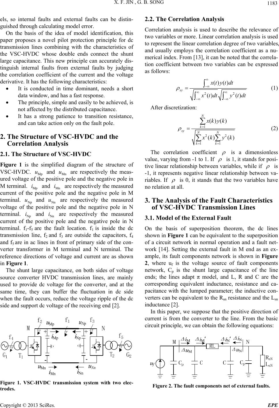 X. F. JIN , G. B. SONG 1183 els, so internal faults and external faults can be distin- guished through calculating model error. On the basis of the idea of model identification, this paper proposes a novel pilot protection principle for dc transmission lines combining with the characteristics of the VSC-HVDC whose double ends connect the shunt large capacitance. This new principle can accurately dis- tinguish internal faults from external faults by judging the correlation coefficient of the current and the voltage derivative. It has the following characteristics: It is conducted in time dominant, needs a short data window, and has a fast response. The principle, simple and easily to be achieved, is not affected by the distributed capacitance. It has a strong patience to transition resistance, and can take action only on the fault pole. 2. The Structure of VSC-HVDC and the Correlation Analysis 2.1. The Structure of VSC-HVDC Figure 1 is the simplified diagram of the structure of VSC-HVDC. Mp and Mn are respectively the meas- ured voltage of the positive pole and the negative pole in M terminal. Mp and Mn are respectively the measured current of the positive pole and the negative pole in M terminal. Np and Nn are respectively the measured voltage of the positive pole and the negative pole in N terminal. uu i i u u N p and Nn are respectively the measured current of the positive pole and the negative pole in N terminal. f1-f5 are the fault location. f1 is inside the dc transmission line, f2 and f3 are outside the capacitors, f4 and f5 are in ac lines in front of primary side of the con- verter transformer in M terminal and N terminal. The reference directions of voltage and current are as shown in Figure 1. ii The shunt large capacitance, on both sides of voltage source converter HVDC transmission lines, are mainly used to provide dc voltage for the converter, and at the same time, they can buffer the fluctuation in dc side when the fault occurs, reduce the voltage ripple of the dc side and support dc voltage of the receiving end [2]. Figure 1. VSC-HVDC transmission system with two elec- trodes. 2.2. The Correlation Analysis Correlation analysis is used to describe the relevance of two variables or more. Linear correlation analysis is used to represent the linear correlation degree of two variables, and usually employs the correlation coefficient as a nu- merical index. From [13], it can be noted that the correla- tion coefficient between two variables can be expressed as follows: 22 () () () () xy xt ytdt x tdty tdt (1) After discretization: 1 22 11 ()() () () N k xy NN kk xkyk x kyk (2) The correlation coefficient is a dimensionless value, varying from -1 to 1. If is 1, it stands for posi- tive linear relationship between variables, while if is -1, it represents negative linear relationship between va- riables. If is 0, it stands that the two variables have no relation at all. 3. The Analysis of the Fault Characteristics of VSC-HVDC Transmission Lines 3.1. Model of the External Fault On the basis of superposition theorem, the dc lines shown in Figure 1 can be equivalent to the superposition of a circuit network in normal operation and a fault net- work [14]. Setting the external fault in M end as an ex- ample, its fault components network is shown in Figure 2, where uf is the voltage source of fault components network, Cp is the shunt large capacitance of the line ends; the lines adapt π model, and L, R and C are the corresponding equivalent inductance, resistance and ca- pacitance with the lumped parameter; the inductive con- verters can be equivalent to the Rsn resistance and the Lsn inductance [2]. In this paper, we suppose that the positive direction of current is from the converter to the line. From the basic circuit principle, we can obtain the following equations: Figure 2. The fault components net of external faults. Copyright © 2013 SciRes. EPE 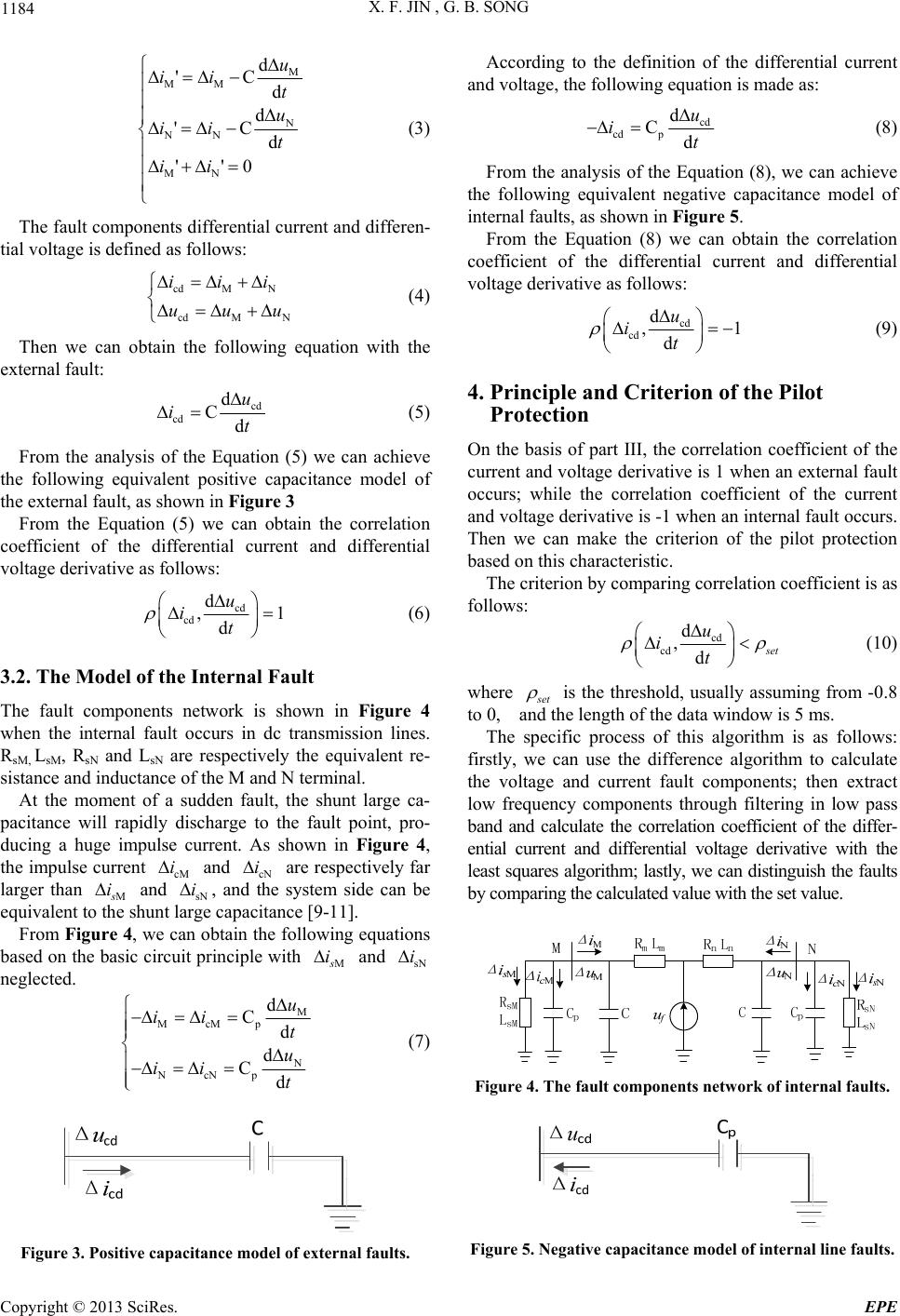 X. F. JIN , G. B. SONG 1184 M MM N NN MN d 'C d d 'C d ''0 u ii t u ii t ii (3) The fault components differential current and differen- tial voltage is defined as follows: cdM N cdM N iii uuu (4) Then we can obtain the following equation with the external fault: cd cd d Cd u it (5) From the analysis of the Equation (5) we can achieve the following equivalent positive capacitance model of the external fault, as shown in Fig u r e 3 From the Equation (5) we can obtain the correlation coefficient of the differential current and differential voltage derivative as follows: cd cd d , d u it 1 (6) 3.2. The Model of the Internal Fault The fault components network is shown in Figure 4 when the internal fault occurs in dc transmission lines. RsM, LsM, RsN and LsN are respectively the equivalent re- sistance and inductance of the M and N terminal. At the moment of a sudden fault, the shunt large ca- pacitance will rapidly discharge to the fault point, pro- ducing a huge impulse current. As shown in Figure 4, the impulse current cM and cN are respectively far larger than M ii s i and sN , and the system side can be equivalent to the shunt large capacitance [9-11]. i From Figure 4, we can obtain the following equations based on the basic circuit principle with M s i and sN i neglected. M McMp N NcNp d Cd d Cd u ii t u ii t (7) Figure 3. Positive capacitance model of external faults. According to the definition of the differential current and voltage, the following equation is made as: cd cd p d Cd u it (8) From the analysis of the Equation (8), we can achieve the following equivalent negative capacitance model of internal faults, as shown in Figure 5. From the Equation (8) we can obtain the correlation coefficient of the differential current and differential voltage derivative as follows: cd cd d , d u it 1 (9) 4. Principle and Criterion of the Pilot Protection On the basis of part III, the correlation coefficient of the current and voltage derivative is 1 when an external fault occurs; while the correlation coefficient of the current and voltage derivative is -1 when an internal fault occurs. Then we can make the criterion of the pilot protection based on this characteristic. The criterion by comparing correlation coefficient is as follows: cd cd d ,d s et u it (10) where s et is the threshold, usually assuming from -0.8 to 0, and the length of the data window is 5 ms. The specific process of this algorithm is as follows: firstly, we can use the difference algorithm to calculate the voltage and current fault components; then extract low frequency components through filtering in low pass band and calculate the correlation coefficient of the differ- ential current and differential voltage derivative with the least squares algorithm; lastly, we can distinguish the faults by comparing the calculated value with the set value. Figure 4. The fault components network of internal faults. Figure 5. Negative capacitance model of internal line faults. Copyright © 2013 SciRes. EPE 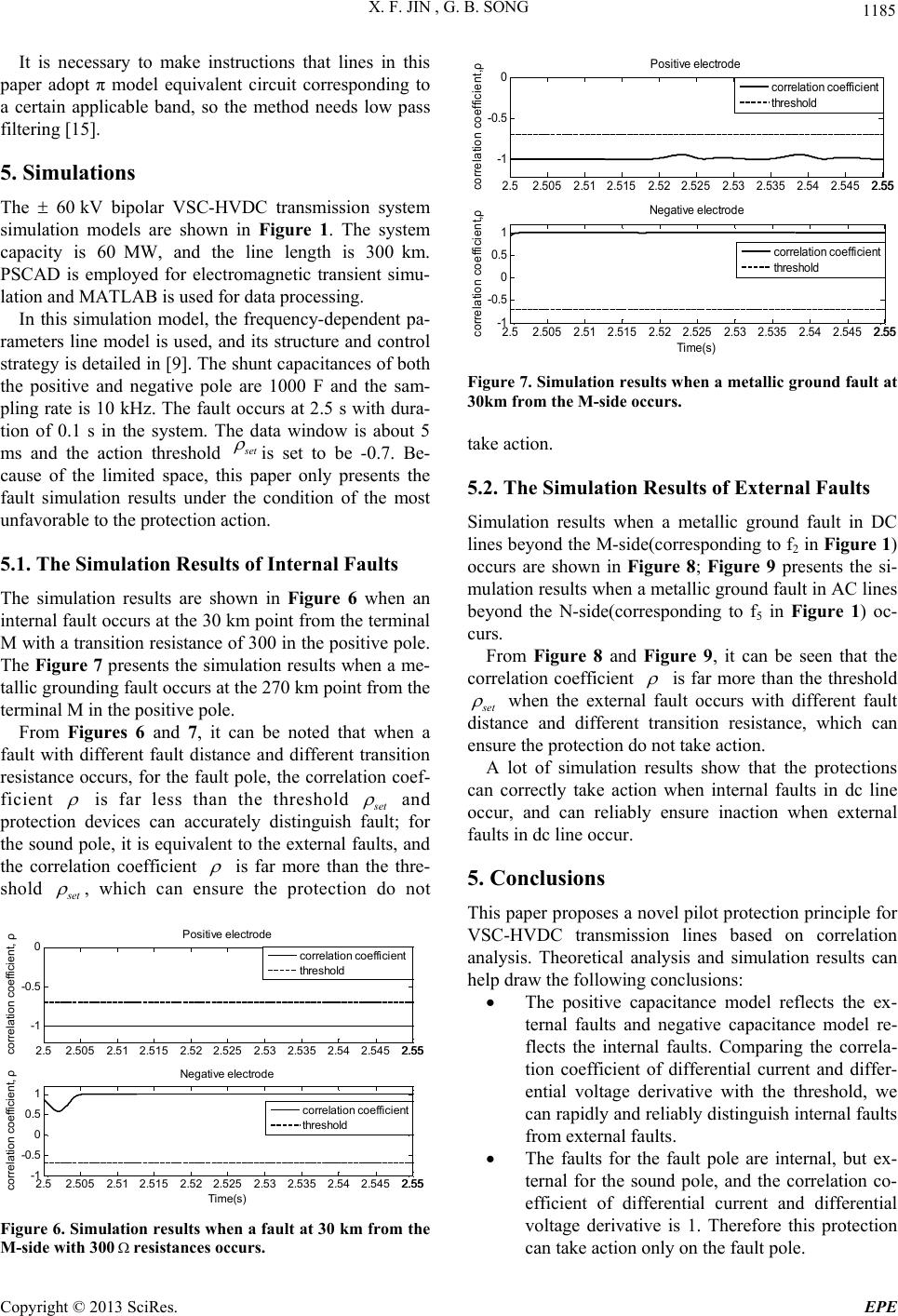 X. F. JIN , G. B. SONG 1185 It is necessary to make instructions that lines in this paper adopt π model equivalent circuit corresponding to a certain applicable band, so the method needs low pass filtering [15]. 5. Simulations The 60 kV bipolar VSC-HVDC transmission system simulation models are shown in Figure 1. The system capacity is 60 MW, and the line length is 300 km. PSCAD is employed for electromagnetic transient simu- lation and MATLAB is used for data processing. In this simulation model, the frequency-dependent pa- rameters line model is used, and its structure and control strategy is detailed in [9]. The shunt capacitances of both the positive and negative pole are 1000 F and the sam- pling rate is 10 kHz. The fault occurs at 2.5 s with dura- tion of 0.1 s in the system. The data window is about 5 ms and the action threshold s et is set to be -0.7. Be- cause of the limited space, this paper only presents the fault simulation results under the condition of the most unfavorable to the protection action. 5.1. The Simulation Results of Internal Faults The simulation results are shown in Figure 6 when an internal fault occurs at the 30 km point from the terminal M with a transition resistance of 300 in the positive pole. The Figure 7 presents the simulation results when a me- tallic grounding fault occurs at the 270 km point from the terminal M in the positive pole. From Figures 6 and 7, it can be noted that when a fault with different fault distance and different transition resistance occurs, for the fault pole, the correlation coef- ficient is far less than the threshold s et and protection devices can accurately distinguish fault; for the sound pole, it is equivalent to the external faults, and the correlation coefficient is far more than the thre- shold s et , which can ensure the protection do not 2.52.5052.512.5152.522.525 2.53 2.5352.542.545 2.552.55 -1 -0.5 0 correlation coefficient, ρ Positive electrode 2.52.5052.512.5152.522.525 2.53 2.5352.542.545 2.552.55 -1 -0.5 0 0.5 1 Ti m e(s) correlation coefficient, ρ Negative electrode correlation coefficient threshold correlation coefficient threshold Figure 6. Simulation results when a fault at 30 km from the M-side with 300resistances occurs. 2.52.505 2.51 2.5152.522.5252.53 2.535 2.542.5452.552.55 -1 -0.5 0 correlation coefficient,ρ Positive electrode 2.52.505 2.51 2.5152.52 2.525 2.53 2.535 2.54 2.545 2.552.55 -1 -0.5 0 0.5 1 Time(s) correlation coefficient,ρ Negative electrode correlation coefficient threshold correlation coefficient threshold Figure 7. Simulation results whe n a metallic ground fault at 30km from the M-side occurs. take action. 5.2. The Simulation Results of External Faults Simulation results when a metallic ground fault in DC lines beyond the M-side(corresponding to f2 in Figure 1) occurs are shown in Figure 8; Figure 9 presents the si- mulation results when a metallic ground fault in AC lines beyond the N-side(corresponding to f5 in Figure 1) oc- curs. From Figure 8 and Figure 9, it can be seen that the correlation coefficient is far more than the threshold s et when the external fault occurs with different fault distance and different transition resistance, which can ensure the protection do not take action. A lot of simulation results show that the protections can correctly take action when internal faults in dc line occur, and can reliably ensure inaction when external faults in dc line occur. 5. Conclusions This paper proposes a novel pilot protection principle for VSC-HVDC transmission lines based on correlation analysis. Theoretical analysis and simulation results can help draw the following conclusions: The positive capacitance model reflects the ex- ternal faults and negative capacitance model re- flects the internal faults. Comparing the correla- tion coefficient of differential current and differ- ential voltage derivative with the threshold, we can rapidly and reliably distinguish internal faults from external faults. The faults for the fault pole are internal, but ex- ternal for the sound pole, and the correlation co- efficient of differential current and differential voltage derivative is 1. Therefore this protection can take action only on the fault pole. Copyright © 2013 SciRes. EPE 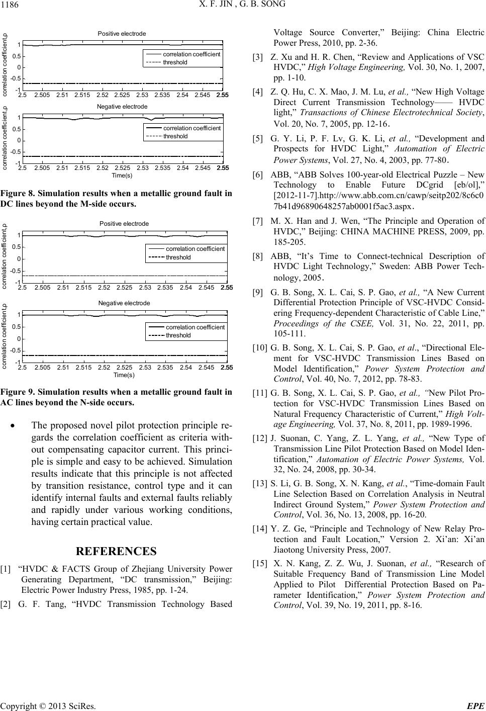 X. F. JIN , G. B. SONG Copyright © 2013 SciRes. EPE 1186 2.52.505 2.512.5152.522.5252.532.5352.54 2.5452.552.55 -1 -0.5 0 0.5 1 correlation coefficient,ρ Positive electrode 2.52.505 2.512.5152.522.525 2.53 2.535 2.54 2.5452.552.5 5 -1 -0.5 0 0.5 1 Tim e(s) correlation coefficient,ρ Negative electrode correlation coefficient threshold correlation coefficient threshold Figure 8. Simulation results when a metallic ground fault in DC lines beyond the M-side occurs. 2.52.505 2.512.5152.522.525 2.532.535 2.542.5452.5 5 2.5 5 -1 -0.5 0 0.5 1 correlation coefficient,ρ Positive electrode 2.52.505 2.512.5152.522.525 2.532.535 2.542.5452.5 5 2.5 5 -1 -0.5 0 0.5 1 Tim e(s ) correlation coefficient,ρ Negative electrode correlation coefficient threshold correlation coefficient threshold Figure 9. Simulation results when a metallic ground fault in AC lines beyond the N-side occur s. The proposed novel pilot protection principle re- gards the correlation coefficient as criteria with- out compensating capacitor current. This princi- ple is simple and easy to be achieved. Simulation results indicate that this principle is not affected by transition resistance, control type and it can identify internal faults and external faults reliably and rapidly under various working conditions, having certain practical value. REFERENCES [1] “HVDC & FACTS Group of Zhejiang University Power Generating Department, “DC transmission,” Beijing: Electric Power Industry Press, 1985, pp. 1-24. [2] G. F. Tang, “HVDC Transmission Technology Based Voltage Source Converter,” Beijing: China Electric Power Press, 2010, pp. 2-36. [3] Z. Xu and H. R. Chen, “Review and Applications of VSC HVDC,” High Voltage Engineering, Vol. 30, No. 1, 2007, pp. 1-10. [4] Z. Q. Hu, C. X. Mao, J. M. Lu, et al., “New High Voltage Direct Current Transmission Technology—— HVDC light,” Transactions of Chinese Electrotechnical Society, Vol. 20, No. 7, 2005, pp. 12-16. [5] G. Y. Li, P. F. Lv, G. K. Li, et al., “Development and Prospects for HVDC Light,” Automation of Electric Power Systems, Vol. 27, No. 4, 2003, pp. 77-80. [6] ABB, “ABB Solves 100-year-old Electrical Puzzle – New Technology to Enable Future DCgrid [eb/ol],” [2012-11-7].http://www.abb.com.cn/cawp/seitp202/8c6c0 7b41d96890648257ab0001f5ac3.aspx. [7] M. X. Han and J. Wen, “The Principle and Operation of HVDC,” Beijing: CHINA MACHINE PRESS, 2009, pp. 185-205. [8] ABB, “It’s Time to Connect-technical Description of HVDC Light Technology,” Sweden: ABB Power Tech- nology, 2005. [9] G. B. Song, X. L. Cai, S. P. Gao, et al., “A New Current Differential Protection Principle of VSC-HVDC Consid- ering Frequency-dependent Characteristic of Cable Line,” Proceedings of the CSEE, Vol. 31, No. 22, 2011, pp. 105-111. [10] G. B. Song, X. L. Cai, S. P. Gao, et al., “Directional Ele- ment for VSC-HVDC Transmission Lines Based on Model Identification,” Power System Protection and Control, Vol. 40, No. 7, 2012, pp. 78-83. [11] G. B. Song, X. L. Cai, S. P. Gao, et al., “New Pilot Pro- tection for VSC-HVDC Transmission Lines Based on Natural Frequency Characteristic of Current,” High Volt- age Engineering, Vol. 37, No. 8, 2011, pp. 1989-1996. [12] J. Suonan, C. Yang, Z. L. Yang, et al., “New Type of Transmission Line Pilot Protection Based on Model Iden- tification,” Automation of Electric Power Systems, Vol. 32, No. 24, 2008, pp. 30-34. [13] S. Li, G. B. Song, X. N. Kang, et al., “Time-domain Fault Line Selection Based on Correlation Analysis in Neutral Indirect Ground System,” Power System Protection and Control, Vol. 36, No. 13, 2008, pp. 16-20. [14] Y. Z. Ge, “Principle and Technology of New Relay Pro- tection and Fault Location,” Version 2. Xi’an: Xi’an Jiaotong University Press, 2007. [15] X. N. Kang, Z. Z. Wu, J. Suonan, et al., “Research of Suitable Frequency Band of Transmission Line Model Applied to Pilot Differential Protection Based on Pa- rameter Identification,” Power System Protection and Control, Vol. 39, No. 19, 2011, pp. 8-16. |

