Energy and Power Engineering, 2013, 5, 1115-1119
doi:10.4236/epe.2013.54B213 Published Online July 2013 (http://www.scirp.org/journal/epe)
Active Power Filter Control Using Adaptive Signal
Pr ocessing Techniques
S. A. Temerbaev, V. P. Dovgun, N. P. Bojarskaja, A. F. Sinyagovski
Siberian Federal University, Institute of Space and Information Technologies, Chair of Systems for Automatics,
Computer-Aided Control and Design, Krasnoyarsk, Russia
Email: temwork@mail.ru
Received February, 2013
ABSTRACT
In this paper a new Active Power Filter (APF) control method is proposed . Computation of the load harmonic compen-
sation current is performed by the adaptive notch infinite impulse response (IIR) filter. Performance of the proposed
scheme has been verified by computer simulation. MATLAB/SIMULINK power system toolbox is used to simulate the
proposed system. The simulation results are presented and confirmed the effectiveness of the proposed method.
Keywords: Active Power Filter; Nonlinear Load; Harmonics
1. Introduction
The widespread use of nonlinear devices within the in-
dustrial, commercial and residential sectors has resulted
in substantial reduction of power quality in electric power
systems. Harmonic distortion produced by nonlinear
loads causes several problems, such as increased power
losses in customer equipment, power transformers and
power lines, flicker, shorter life of organic insulation [1].
In recent decades, passive and active harmonic filters
have been recognized as the most effective solutions for
harmonic mitigation.
The passive harmonic filters (PHF), consisting from
capacitors, inductors and resistors have been trad itionally
used for this task [1, 3]. The main advantages of PHF are
design simplicity and low cost. Th ey don’t require a reg-
ular service and can correct the power factor. But PHF
have many disadvantages, such as fixed compensation
characteristics, large size and resonance problems.
In recent years, active power filters (APF) have been
widely investigated for the compensation of harmonic
currents. APF allow to compensating the harmonics and
unbalance, together with power factor correction. Mod-
ern active harmonic filters have superior filtering char-
acteristics, smaller in physical size, more flexible in ap-
plication compared to their passive counterparts. They
are widely used in industrial, commercial, utility net-
works and in electric traction systems [1, 2].
Calculation of compensating signals is the important
part of APF control and affects their transient as well as
steady-state performance. Different control methods have
been proposed, ranging from the use of fast Fourier
transform (FFT) to the instantaneous P-Q theory, artifi-
cial neural networks and adaptive notch filters.
In this paper, an efficient method to obtain compen-
sating signals for the active harmonic filter is considered.
The load harmonic compensation is performed by using
the lattice-form adaptive notch IIR filter. Simulation re-
sults confirm the effectiveness of the proposed method.
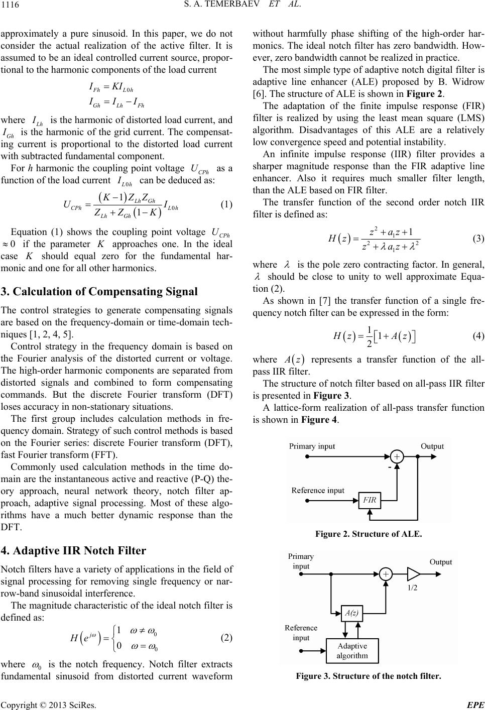
2. Shunt Active Power Filter
The active power filters are basically classified into two
types: the shunt type and the series type. One of the most
popular active power filters is the shun t APF. It’s advan-
tages are good current con trol capability, easy p rotection,
and high reliability over series filters. The single-phase
operation scheme of a shunt active filter is shown in
Figure 1.
For each harmonic of order h the nonlinear load is
presented by the equivalent Norton circuit, which con-
sists of the current source
L
h
I
with in-parallel imped-
ance
L
h
Z
. The grid is presented by the Thevenin equiv-
alent, which consists of the voltage source with
series impedance G
U
G
Z
.
The shunt active power filter compensates current
harmonics by injecting equal but opposite harmonic
compensating current, so that the compensated current is
Figure 1. Operation scheme of shunt active filter.
Copyright © 2013 SciRes. EPE
S. A. TEMERBAEV ET AL.
1116
approximately a pure sinusoid. In this paper, we do not
consider the actual realization of the active filter. It is
assumed to be an ideal controlled current source, propor-
tional to the harmonic components of the load current
0FhL h
GhLh Fh
IKI
I
II

where
L
h
I
is the harmonic of distorted load current, and
Gh
I
is the harmonic of the grid current. The compensat-
ing current is proportional to the distorted load current
with subtracted fundamental component.
For h harmonic the coupling point voltage CPh as a
function of the l oad cu rrent U
0
L
h
I
can be deduced as:


0
1
1
Lh Gh
CPhL h
Lh Gh
KZZ
UI
ZZ K
 (1)
Equation (1) shows the coupling point voltage CPh
if the parameter U
0
K
approaches one. In the ideal
case
K
should equal zero for the fundamental har-
monic and one for all other harmonics.
3. Calculation of Compensating Signal
The control strategies to generate compensating signals
are based on the frequency-domain or time-domain tech-
niques [1, 2, 4, 5].
Control strategy in the frequency domain is based on
the Fourier analysis of the distorted current or voltage.
The high-order harmonic components are separated from
distorted signals and combined to form compensating
commands. But the discrete Fourier transform (DFT)
loses accuracy in non-stationary situations.
The first group includes calculation methods in fre-
quency domain. Strategy of such control methods is based
on the Fourier series: discrete Fourier transform (DFT),
fast Fourier transform (FFT).
Commonly used calculation methods in the time do-
main are the instantaneou s active and reactive (P-Q) the-
ory approach, neural network theory, notch filter ap-
proach, adaptive signal processing. Most of these algo-
rithms have a much better dynamic response than the
DFT.
4. Adaptive IIR Notch Filter
Notch filters have a variety of applications in the field of
signal processing for removing single frequency or nar-
row-band sinusoidal interference.
The magnitude characteristic of the ideal notch filter is
defined as:

0
0
1
0
j
He
(2)
where 0
is the notch frequency. Notch filter extracts
fundamental sinusoid from distorted current waveform
without harmfully phase shifting of the high-order har-
monics. The ideal notch filter has zero bandwidth. How-
ever, zero bandwidth cannot be realized in practice.
The most simple type of adaptive n otch digital filter is
adaptive line enhancer (ALE) proposed by B. Widrow
[6]. The structure of ALE is shown in Figure 2.
The adaptation of the finite impulse response (FIR)
filter is realized by using the least mean square (LMS)
algorithm. Disadvantages of this ALE are a relatively
low convergence speed and potential instability.
An infinite impulse response (IIR) filter provides a
sharper magnitude response than the FIR adaptive line
enhancer. Also it requires much smaller filter length,
than the ALE based on FIR filter.
The transfer function of the second order notch IIR
filter is defined as:

21
2
1
1zaz
Hz zaz
2


(3)
where
is the pole zero contracting factor. In general,
should be close to unity to well approximate Equa-
tion (2).
As shown in [7] the transfer function of a single fre-
quency notch filter can be expressed in the form:
 
11
2
H
zA
z
(4)
where
A
z represents a transfer function of the all-
pass IIR filter.
The structure of notch filter based on all-pass IIR filter
is presented in Figure 3.
A lattice-form realization of all-pass transfer function
is shown in Figure 4.
Figure 2. Structure of ALE.
Figure 3. Structure of the notch filter.
Copyright © 2013 SciRes. EPE
S. A. TEMERBAEV ET AL.
Copyright © 2013 SciRes. EPE
1117
of its low complexity and high-speed convergence. Up-
date of the coefficients 1 and , using gradient algo-
rithm, is given as follows:
k2
k
   

11
2
11
iiii ii
i
knknenr nenrn
Dn

 
is an adaptation step. Parameter
i
Dn
where
is
defined: as
Figure 4. All-pass lattice IIR filter.

22
11
1
iiii
nDn en rn

D

In Figure 4 x(n) and y(n) are input and output signals,
respectively. Transfer function of the lattice IIR filter is
the following:
is a forgetting factor: 01
. where
5. MATHLAB-Based Simulation
b/Simulink to
APF is analyzed by consider-
in
 



21
12
21
212
1
11
Yzzkk zk
Az Xz kzkk z

 
 2

(5) The system was simulated using MathLa
verify the proposed algorithm. Schematic diagram of the
proposed controlled shunt APF is shown in Figure 6.
The linear load is defined as resistance Rlin = 100 Ohms,
non-linear load includes two rectifiers with RL load on
the dc side. Simulation process is divided into steps:
connection of the first rectifier, connection of APF and
connection of the second rectifier. All simulation process
is presented in Figure 7.
The performance of the
The polynomials of nominator and denominator of
Equation (5) have mirror symmetry. Accordingly, lattice
IIR-filter realizes all-pass transfer function with module
equal 1 in the all frequency range.
Transfer function of notch filter, shown in Figure 3 is
presented as:




21
1
2
212
211
1
211
zkz k
Hz kzkk z


 
2
1
(6) g of the following cases.
where 1 is the adaptive coefficient, which should con-
verge to 0
kcos
to reject a sinusoid with frequency
0
. Frequency suppression of notch filter can be modi-
fied by and stopband widt h by.
1 2
Adaptive IIR filter in Figure 3 is adapted using adap-
tive algorithms related to the lattice FIR filters. The
structure of the lattice second-o rder FIR filter is shown in
Figure 5. In this article gradient lattice algorithm [8] is
used for adaptation purposes. It has been chosen because
k k
Figure 5. FIR lattice filter.
Figure 6. MATHLAB scheme of shunt APF system.
S. A. TEMERBAEV ET AL.
1118
Figure 7. Simulation results.
.1. Case 1
Figure 6 in t = 0.1 sec the first rectifier is
5.2. Case 2
load is increased in t = 0.5 sec. Proposed
6. Conclusions
el adaptive method for grid current
Table 1. THD before and after 0.3 sec.
5
As shown in
connected to the grid. In the 0.3 sec the shunt APF is
connected to the grid and starts compensating harmonics
component of the non-linear load current. Changing of
THD is demonstrated in the Table 1. Grid, linear load
and non-linear load currents are presented in Figure 7.
The nonlinear
technique of calculation compensation signal operates
properly without severe transients at the instants of step
load chang e. THD is presented in Table 2.
In this paper, a nov
harmonic compensation is proposed. The load harmonic
compensation was performed by using the lattice-form
adaptive notch IIR filter. It was shown that adaptive
THD %
Signal nameBefore After
I g 11.29 1.35
I lin 5.44 0.64
I nonl 34.79 40.32
Table 2. THD before and after 0.5 sec.
THD %
Signal nameBefore After
I g 1.35 1.98
I lin 0.64 1.14
I nonl 40.32 40.28
Copyright © 2013 SciRes. EPE
S. A. TEMERBAEV ET AL. 1119
notch filtetive har-
monic filter for the sake of hic mitigation
prooach does not neey training o
notch filter. Performathe proposed l system
is verified by computer simulation. MATLAB/SIM
LINK power system tis used to sime the pro-
posed system. The ults presented
showing the effectiveness of the proposed method.
REFERENCES
[1] H. Akagiings of th
IEEE, Vol. 93, No. 12, 2005,-2141.
9/JPROC.2005.859603
r can be successfully employed in ac
armon
d an. The
f the posed apprnce of contro U-
oolbox ulat
simulation resare
, “Active Harmonic Filters,” Proceede
pp. 2128
doi:10.110
[2] B. Singh, K. Al-Hnd A. Chandreview
Ace Filters for Power Quality Improvent,” IEEE
Trans. on Industria Vol. 46, No. 5, 1999, pp.
960-971. doi:10.1109/41.793345
addad aa, “A R of
tiv me
l Electronics,
[3] J. Das, “Passive Filters – Potentialities and mitations
IEEE Transactions, Vol. 40, No.
Li,”
tions on Industry Applica
1, 2004, pp. 232-241. doi:10.1109/TIA.2003.821666
[4] L. Asiminoaei, F. Blaabjerg and S. Hansen, “Detection is
Key,” IEEE Industry Applications Magazine,2007, pp.
22-33.
[5] “A Single-phase DG Generation Unit with Shunt Active
Power Filter Capability by Adaptive Neural Filtering,”
IEEE Transactions on Industrial Electronics, Vol. 55, No.
5, 2008, pp. 2093-2110. doi:10.1109/TIE.2008.918642
[6] B. Widrow and S. P. Stearns, “Adaptive Signal Process-
ing of Englewood Cliffs,” NJ: Prentice-Hall, Inc. 1985.
[7] P. A. Regalia, S. K. Mitra and P. P. Vaidyanathan, “The
Digital All-pass Filter: A Versatile Signal Processing
Building Block,” Proceedings of IEEE, Vol. 76, No. 1,
1998, pp. 19-37. doi:10.1109/5.3286
[8] Hodkiss and J. F. Presley, “Adaptive Tracking of Multi-
ple Sinusoids Whose Power Levels are Widely Sepa-
rated,” IEEE Transactions on Circuits and Systems, Vol.
CAS-28, No. 6, 1981, pp. 550-561.
Copyright © 2013 SciRes. EPE