 Energy and Power Engineering, 2013, 5, 1109-1114 doi:10.4236/epe.2013.54B212 Published Online July 2013 (http://www.scirp.org/journal/epe) Influence of Phase Compensation Method on Magnetizing Inrush Identification Xiangfei Sun, Jianping Zhou Department of Electrical Power Engineering, Kunming University of Science and Technology, Kunming, China Email: fly_beauty@163.com, fqyd926@163.com Received April, 2013 ABSTRACT The effect of different phase compensation methods on second harmonic ratio of magnetizing inrush is investigated. The flux linkage expression of switching on an unload transformer is deduced and influence factors of inrush current are analyzed firstly. Then the difference of two kinds of phase compensation methods, from star to delta and from delta to star connection, is compared. The second harmonic ratio of symmetric inrush is analyzed specially. Using inrush waveform of a real transformer, second harmonic ratio of phase inrush and that of differential current under two kinds of phase compensation methods are calculated respectively. Furthermore, based on the calculation results, the effect of two kinds of phase compensation methods on the inrush current identification is proved. The analysis and calculation results show that the second harmonic ratio of symmetric inrush caused by phase compensation method, from star to delta, is not low. Moreover, the split-phase blocking scheme should not be adopted for differential protection of from delta to star compensation. Using the phase current without compensation to calculate the ratio of second harmonic is inadvisable too. Keywords: Transformer; Differential Protection; Magnetizing Inrush ; Second Harmonic; Phase Compensation 1. Introduction When an unload transformer is energized, it will create a large magnetizing inrush, which will cause the mal- op- eration of transformer differential protection. In order to prevent mal-operation, many techniques have been in- vestigated in the design and operation of transformer differential protection [1-3]. However, the inrush current identification algorithm that has been widely used is still the second harmonic restraint scheme [4-6]. Second harmonic restraint mainly includes two schemes. One is single phase blocking three-phase scheme, i.e. all three-phase differential relays will be blocked when any phase second harmonic ratio is larger than setting valve. The other is split-phase blocking scheme, i.e. only the relay of the phase whose second harmonic ratio is larger than setting valve will be blocked. In practice, for Y-delta connected transformers, which are used widely in power system, phase compensation should be carried out to eliminate the imbalance current in the circuit loop of transformer differ ential relays [7-9 ]. Phase compensation mainly includes two methods, one is from star to delta phase compensation, the other is from delta to star phase compensation. As a result, different phase compensation methods will lead to different influ- ence on the differential current of transformer differential protection. Therefore, which second harmonic blocking scheme should be adopted need to be researched [10-13]. How- ever, the previous researches have some opposite view- points. Literature [10] presents that from star to delta phase compensation method will lead to symmetric in- rush, which results in inrush characteristic is not obv ious and the second harmonic content of differential current reduced. So split-phase blocking scheme is not adopted. Literature [11] indicates that split-phase blocking scheme is suitable for from delta to star phase compensation me- thod. Literature [12] proposes that the two phase com- pensation methods have similarities in inrush identifica- tion, and split-p hase blocking scheme may mal operation under the both two methods. Literature [13] presents that the two compensation methods both can change the har- monics of differential current, so directly take the un- compensated current to calculate the second harmonic ratio can achieve split-phase brake scheme. Aim to investigate the influence of different phase compensation methods on second harmonic restraint scheme; the paper analyzes the influencing factors of magnetizing inrush firstly. Then the difference of two kinds of phase compensation methods are compared, especially focus on the analysis of the second harmonic ratio in symmetric inrush. Based on the inrush waveform of a real transformer, influence of two phase compensa- Copyright © 2013 SciRes. EPE  X. F. SUN, J. P. ZHOU 1110 tion methods on identifying magnetizing inrush is ana- lyzed in depth, and problems of transformer differential protection device on the second harmonic restraint scheme is investigated. 2. Influence Factors of Magnetizing Inrush Equivalent circuit of single-phase transformer switching on without load is sh own in Figure 1. As the second side of transformer is unloaded and core loss is small, the equivalent resistance R m which represents core loss can be ignored. Assuming that voltage source us is a sine voltage, i.e. us=Umsin( t+ ), where Um and are volt- age amplitude and closing angle respectively. Rs and L s are the equivalent resistance and inductance of system respectively, R σ and L σ are the equivalent leakage resis- tance and leakage inductance of transformer respectively. Lm is equivalent magnetizing inductance. Defining ψ is the total equivalent flux linkage of the circuit, i.e. ψ=ψs+ψσ+ψm, where ψs, ψσ and ψm are cre- ated by Ls, Lσ and Lm respectively. R is the total equiva- lent resistance of the circuit, i.e. R=Rs+Rσ. Voltage equa- tion of the circuit shown in Figure 1 can b e e x p r es s ed as d sin( )d sm m uUtRi t (1) In Equation (1), ψ=ψs+ψσ+ψm=(Ls+Lσ+Lm)im=Lim, where im is magnetizing current. Since Ls and L σ can be regarded as constant, the relationship between ψm and im is the magnetization curve m=f (im). When transformer is saturated, the relationship between ψm and im will be nonlinear, which means Lm is a nonlinear inductance. So the solution of Equation (1) is hard to obtain. Because voltage mainly varies with the flux linkage, and R has little effect on the voltage. Therefore Lm can be consid- ered as an average inductance of the transformer tran- sient process. Thus L can be regarded as constant. The simplified equation will be dsin( ) dm RUt Lt (2) The solution of Equation (2) consists of the steady component and the transient component , that is 1 22 sin(tg ) () e m Rt L UL Lt R RL C - (3) L s R s u s R L L m K i m Figure 1. Equivalent circuit of single-phase transformer switching on without load. In Equation (3), C is integration constant, which is depended on initial condition. Considering that R<< L, so it will be 1 tg 90 L R (4) 22 () mm m UU L RL (5) In equation (5), m is the amplitude of flux linkage that transformer is in steady operation. Thus Equatio n (3) can be expressed as cos() e t mtC (6) The integration constan t C is depended on the residual magnetism ψr that switching on moment t=0, that is cos m Cr (7) Therefore, the solution of flux linkage can be obtained cos() (cos)e t mm t r (8) According to Equation (8), it is can be seen that the essential reason for occurring magnetizing inrush is the saturation of transformer core, which caused by an ape- riodic flux that generated to restrain the flux mutation when energizing an unload transformer. Moreover, as Equation (8) expresses, the factors that mainly affect the magnetizing inrush are closing angle , the amplitude and polarity of residual magnetism ψr. Obviously, mag- netizing inrush will be maximum when closing angle =0°. And magnetizing inru sh will be zero when closing angle =90°. If the polarity of magnetizing fluxes when transformer switching on is same with that of residual magnetism, saturation of transformer core may be more serious. On the contrary, if the polarities of magnetizing flux and residual magnetism are opposite, it will be help to reduce magnetizing inru sh. 3. Influence of Phase Compensation Methods on Characteristics of Magnetizing Inrush For Y-delta connected transformers, which are used widely in power system, the phase angle of current in star(Y) side lags 30°than that in delta(△) side. In order to eliminate the imbalance current in the circuit loop of transformer differential relays, the amplitude and phase angle of current should be corrected before the trans- former differential protection discrimination. The correc- tion of current amplitude and phase angle is called as phase compensation. The traditional phase compensation method is carried out by adjusting the mode of connection of current transformers (CT), i.e. three CTs on transformer Y side is connected into a delta, while CTs on transformer delta Copyright © 2013 SciRes. EPE 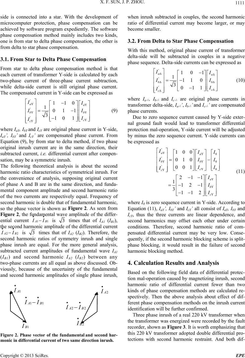 X. F. SUN, J. P. ZHOU. 1111 side is connected into a star. With the development of microcomputer protection, phase compensation can be achieved by software program expediently. The software phase compensation method mainly includes two kinds, one is from star to delta phase compensation, the other is from delta to star phase compensation. 3.1. From Star to Delta Phase Compensation From star to delta phase compensation method is that each current of transformer Y-side is calculated by each two-phase current of three-phase current subtraction, while delta-side current is still original phase current. The compensated current in Y-side can be expressed as ' ' ' 110 101 1 310 1 aa b c c I b I I (9) where IaY, IbY and IcY are original phase current in Y-side, IaY’, IbY’ and I cY’ are compensated phase current. From Equation (9), by from star to delta method, if two phase original inrush current are in the same direction, their subtracted current, i.e. differential current after compen- sation, may be a symmetric inrush. The following theoretical analysis is about the second harmonic ratio characteristics of symmetrical inrush. For the convenience of analysis, supposing original current of phase A and B are in the same direction, and funda- mental component amplitude and second harmonic ratio of the two currents are respectively equal. Frequency of second harmonic is double that of fundamental harmonic, so the phase vector is shown as Figure 2. As seen from Figure 2, the fundamental wave amplitude of the differ- ential current 1AB1 I is 3 times that of IA1 (IB1), the second harmonic amplitude of the differential current 2AB2 I is 3 times that of IA2 (IB2). Therefore, the second harmonic ratios of symmetry inrush and single phase inrush are equal. For the more general analysis, subtracted current amplitudes of fundamental wave IA1 (IB1) and second harmonic IA2 (IB2) between any two-phase currents are all equal as above discussed. Ob- viously, because of the uncertainty of the fundamental and second harmonic amplitudes of single phase inrush, 2 2B 22AB I 1 1B 11AB I Figure 2. Phase vector of the fundamental and second har- monic in differential current of two same direction inrush. when inrush subtracted in couples, the second harmonic ratio of differential current may become larger, or may become smaller. 3.2. From Delta to Star Phase Compensation With this method, original phase current of transformer delta-side will be subtracted in couples in a negative phase sequence. Delta-side currents can be expressed as ' ' ' 10 1 111 0 3011 aa bb c c I I I (10) where I a △ , Ib △ and Ic △ are original phase currents in transformer delta-side, Ia △ ’, Ib △ ’ and Ic △ ’ are compensated phase currents. Due to zero sequence current caused by Y-side exter- nal ground fault would lead to transformer differential protection mal-operation, Y-side current will be adjusted by minus the zero sequence current. Y-side currents can be expressed as ' 0 '0 '0 100 010 001 211 1 121 3112 aa bb c c a b c I I II I I I I I (11) where I0 is zero sequence current in Y-side. According to Equation (11), IaY’, IbY ’ and IcY’ all consist of IaY, IbY and IcY, thus the three currents are linear dependence, and second harmonics may offset each other under certain conditions. Therefore, second harmonic ratio of com- pensated differential current may be very low. Conse- quently, if the second harmonic blocking scheme is split- phase blocking, it would result in the failure of second harmonic bl o cking m e t h od. 4. Calculation Results and Analysis Based on the following field data of differential protec- tion mal-operation caused by magnetizing inrush, second harmonic ratio of differential current fewer than two kinds of phase compensation methods are calculated re- spectively. Then the above analysis about effect of dif- ferent phase compensation methods on the inrush current identification will be further confirmed. Three phase inrush of a real 220 kV tran sformer when the transformer was energized were recorded by the fault recorder, shown as Figure 3. It is worth emphasizing that this 220 kV transformer adopted double differential pro- tections with second harmonic restraint. And both dif- Copyright © 2013 SciRes. EPE 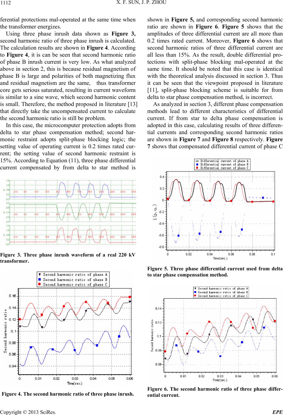 X. F. SUN, J. P. ZHOU 1112 ferential protections mal-operated at th e same time when the transformer energizes. Using three phase inrush data shown as Figure 3, second harmonic ratio of three phase inrush is calculated. The calculation results are shown in Figure 4. According to Figure 4, it is can be seen that second harmonic ratio of phase B inrush current is very low. As what analyzed above in section 2, this is because residual magnetism of phase B is large and polarities of both magnetizing flux and residual magnetism are the same, thus transformer core gets serious saturated, resulting in current waveform is similar to a sine wave, which second harmonic content is small. Therefore, the method proposed in literature [13 ] that directly take the uncompensated current to calculate the second harmonic ratio is still b e problem. In this case, the microcomputer protection adopts from delta to star phase compensation method; second har- monic restraint adopts split-phase blocking logic; the setting value of operating current is 0.2 times rated cur- rent; the setting value of second harmonic restraint is 15%. According to Equation (11), three phase differential current compensated by from delta to star method is Figure 3. Three phase inrush waveform of a real 220 kV transformer. Figure 4. The second harmonic ratio of three phase inrush. shown in Figure 5, and corresponding second harmonic ratio are shown in Figure 6. Figure 5 shows that the amplitudes of three differential current are all more than 0.2 times rated current. Moreover, Figure 6 shows that second harmonic ratios of three differential current are all less than 15%. As the result, double differential pro- tections with split-phase blocking mal-operated at the same time. It should be noted that this case is identical with the theoretical analysis discussed in section 3. Thus it can be seen that the viewpoint proposed in literature [11], split-phase blocking scheme is suitable for from delta to star phase compensation method, is incorrect. As analyzed in section 3, different phase compensation methods lead to different characteristics of differential current. If from star to delta phase compensation is adopted in this case, calculating results of three differen- tial currents and corresponding second harmonic ratios are shown in Figure 7 and Figure 8 respectively. Figure 7 shows that compensated differential current of phase C Figure 5. Three phase differential current used from delta to star phase compensation method. Figure 6. The second harmonic ratio of three phase differ- ential current. Copyright © 2013 SciRes. EPE 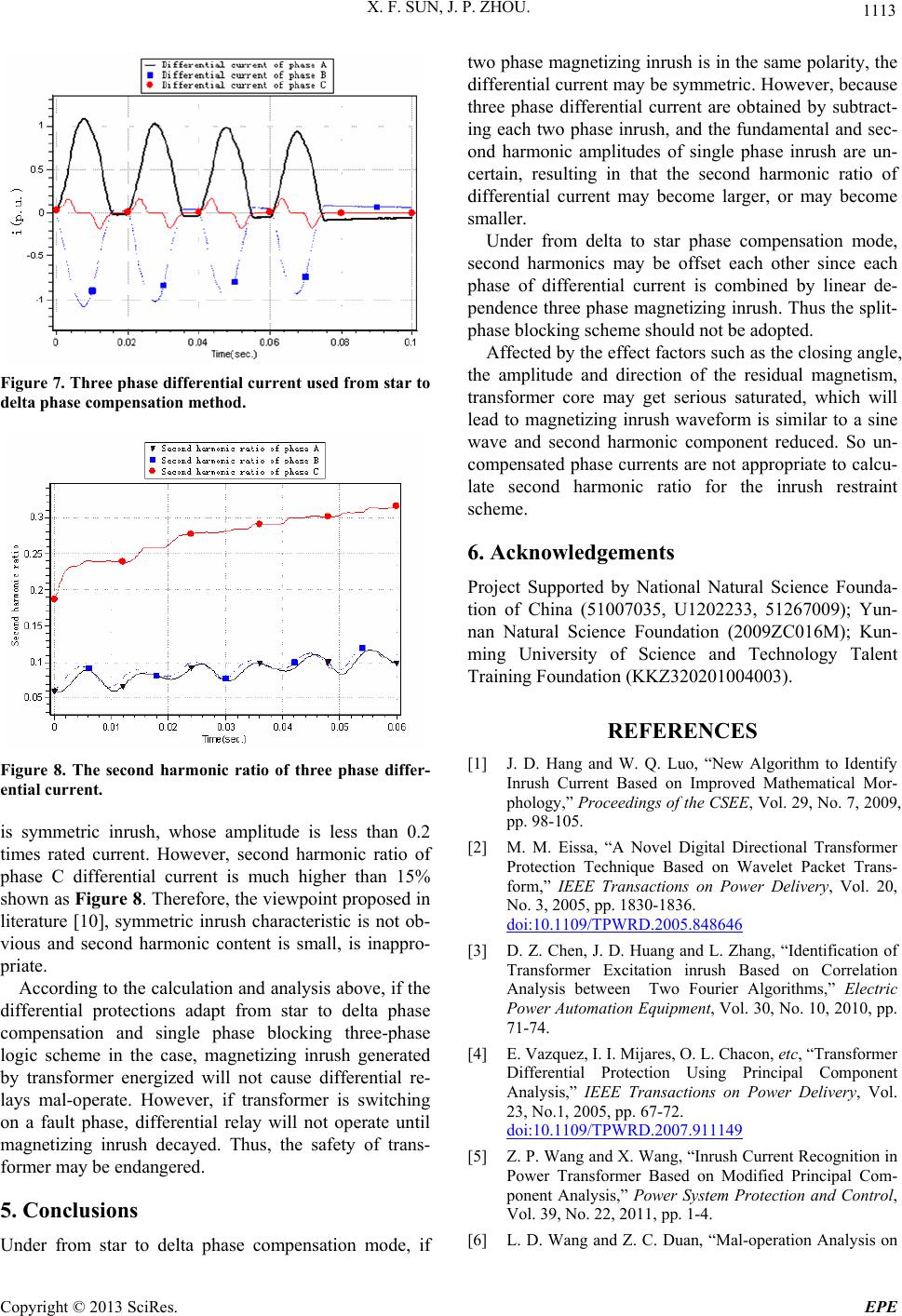 X. F. SUN, J. P. ZHOU. 1113 Figure 7. Three phase differential current used from star to delta phase compensation method. Figure 8. The second harmonic ratio of three phase differ- ential current. is symmetric inrush, whose amplitude is less than 0.2 times rated current. However, second harmonic ratio of phase C differential current is much higher than 15% shown as Figure 8. Theref ore, the viewpoin t propo sed in literature [10], symmetric inrush characteristic is not ob- vious and second harmonic content is small, is inappro- priate. According to the calculation and analysis above, if the differential protections adapt from star to delta phase compensation and single phase blocking three-phase logic scheme in the case, magnetizing inrush generated by transformer energized will not cause differential re- lays mal-operate. However, if transformer is switching on a fault phase, differential relay will not operate until magnetizing inrush decayed. Thus, the safety of trans- former may be endangered. 5. Conclusions Under from star to delta phase compensation mode, if two phase magnetizing inrush is in the same polarity, the differential current may be symmetric. However, because three phase differential current are obtained by subtract- ing each two phase inrush, and the fundamental and sec- ond harmonic amplitudes of single phase inrush are un- certain, resulting in that the second harmonic ratio of differential current may become larger, or may become smaller. Under from delta to star phase compensation mode, second harmonics may be offset each other since each phase of differential current is combined by linear de- pendence three ph ase magnetizing inrush . Thus the split- phase blocking scheme should not be ad o pt ed. Affected by the effect factors such as the closing angle, the amplitude and direction of the residual magnetism, transformer core may get serious saturated, which will lead to magnetizing inrush waveform is similar to a sine wave and second harmonic component reduced. So un- compensated phase currents are not appropriate to calcu- late second harmonic ratio for the inrush restraint scheme. 6. Acknowledgements Project Supported by National Natural Science Founda- tion of China (51007035, U1202233, 51267009); Yun- nan Natural Science Foundation (2009ZC016M); Kun- ming University of Science and Technology Talent Training Foundation (KKZ320201004003). REFERENCES [1] J. D. Hang and W. Q. Luo, “New Algorithm to Identify Inrush Current Based on Improved Mathematical Mor- phology,” Proceedings of the CSEE, Vol. 29, No. 7, 2009, pp. 98-105. [2] M. M. Eissa, “A Novel Digital Directional Transformer Protection Technique Based on Wavelet Packet Trans- form,” IEEE Transactions on Power Delivery, Vol. 20, No. 3, 2005, pp. 1830-1836. doi:10.1109/TPWRD.2005.848646 [3] D. Z. Chen, J. D. Huang and L. Zhang, “Identification of Transformer Excitation inrush Based on Correlation Analysis between Two Fourier Algorithms,” Electric Power Automation Equipment, Vol. 30, No. 10, 2010, pp. 71-74. [4] E. Vazquez, I. I. Mijares, O. L. Chacon, etc, “Transformer Differential Protection Using Principal Component Analysis,” IEEE Transactions on Power Delivery, Vol. 23, No.1, 2005, pp. 67-72. doi:10.1109/TPWRD.2007.911149 [5] Z. P. Wang and X. Wang, “Inrush Current Recognition in Power Transformer Based on Modified Principal Com- ponent Analysis,” Power System Protection and Control, Vol. 39, No. 22, 2011, pp. 1-4. [6] L. D. Wang and Z. C. Duan, “Mal-operation Analysis on Copyright © 2013 SciRes. EPE 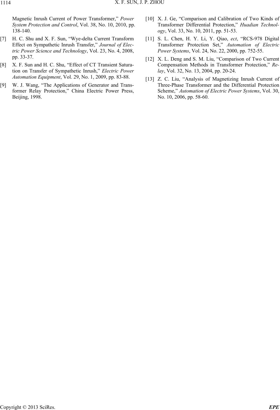 X. F. SUN, J. P. ZHOU Copyright © 2013 SciRes. EPE 1114 Magnetic Inrush Current of Power Transformer,” Power System Protection and Control, Vol. 38, No. 10, 2010, pp. 138-140. [7] H. C. Shu and X. F. Sun, “Wye-delta Current Transform Effect on Sympathetic Inrush Transfer,” Journal of Elec- tric Power Science and Technology, Vol. 23, No. 4, 2008, pp. 33-37. [8] X. F. Sun and H. C. Shu, “Effect of CT Transient Satura- tion on Transfer of Sympathetic Inrush,” Electric Power Automation Equipment, Vol. 29, No. 1, 2009, pp. 83-88. [9] W. J. Wang, “The Applications of Generator and Trans- former Relay Protection,” China Electric Power Press, Beijing, 1998. [10] X. J. Ge, “Comparison and Calibration of Two Kinds of Transformer Differential Protection,” Huadian Technol- ogy, Vol. 33, No. 10, 2011, pp. 51-53. [11] S. L. Chen, H. Y. Li, Y. Qiao, ect, “RCS-978 Digital Transformer Protection Set,” Automation of Electric Power Systems, Vol. 24, No. 22, 2000, pp. 752-55. [12] X. L. Deng and S. M. Liu, “Comparison of Two Current Compensation Methods in Transformer Protection,” Re- lay, Vol. 32, No. 13, 2004, pp. 20-24. [13] Z. C. Liu, “Analysis of Magnetizing Inrush Current of Three-Phase Transformer and the Differential Protection Scheme,” Automation of Electric Power Systems, Vol. 30, No. 10, 2006, pp. 58-60.
|